 Quick Installation Guide
Indoor/Outdoor Access Point
 Visit https://www.tp-link.com/support/setup-video/ or scan the QR code to search for the setup video of your product model.
 https://www.tp-link.com/support/setup-video/
Overview
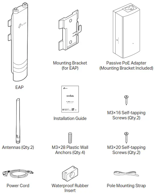
Package Contents
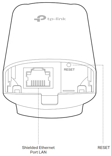
 Panel Layout
 SYS LED Explanation
| LED Status | Indication |
| Flashes green twice | Initialization is completed. |
| Solid green | The device is initializing or working proper |
| Flashing yellow | System errors. RAM, Flash, Ethernet, WLAN or firmware may be malfunctioning. |
| Flashing yellow, green | Firmware update is in progress. Do not disconnect or power off the device. |
| Quickly flashing yellow, green | The device is being reset to its factory default settings. |
| Flashing green slowly (Only for EAP225-Outdoor) | The device is in an isolated state. |
Passive PoE Adapter
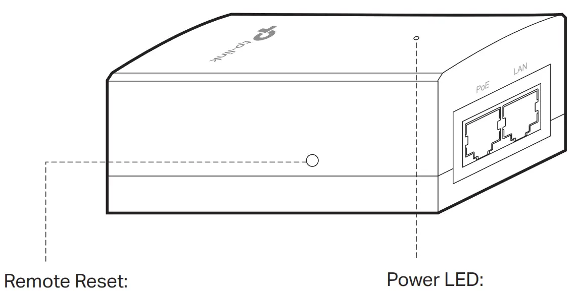
Press and hold for about 8 seconds until the LED is quickly flashing yellow then green. The EAP will restore to factory default settings.
On: Power on, Off: Power off
Note: EAP225-Outdoor does not support the Remote Reset feature
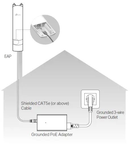
Lightning and ESD Protection
Before mounting the EAP, you should consider Lightning and ESD Protection to ensure safety.
Proper grounding is extremely important for outdoor devices. By using a shielded CAT5e (or above) cable for connection, you can reduce the damage of ESD attacks.
Mount the EAP
The EAP can be pole-mounted or wall-mounted. Follow the steps below for the appropriate installation.
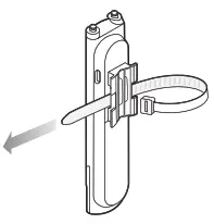
Option 1: Pole Mounting
Step 1:
Lead the end of the pole mounting strap through the back of the EAP.
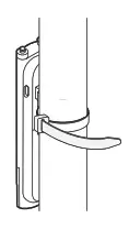
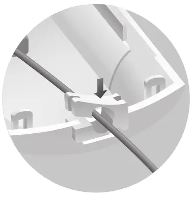
Step 2:
Position the EAP and wrap the pole mounting strap around the pole. Feed the end through the screw-block and tighten the strap until the EAP is secure.
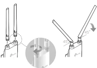
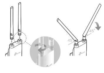
Step 3:
Connect the antennas to the EAP. For optimal Wi-Fi performance, adjust the direction of the antennas. It is recommended to position the antennas at 45-degree angles.
Option 2: Wall Mounting
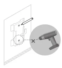
Step 1:
Place the mounting bracket (for EAP) in the right position. Mark two positions for the screw holes. Drill two 6 mm holes for the screws at the marked positions.
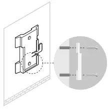
 Step 2:
Insert the plastic wall anchors into the 6 mm holes. Align the bracket (for EAP) to the plastic wall anchors and drive the self-tapping screws into the anchors through the bracket (for EAP).
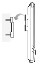
 Step 3:
Align the mounting tabs on the back of the EAP with the slot of the mounting bracket (for EAP). Push and slide the EAP downward until it locks into place.
Step 4:
Connect the antennas to the EAP. For optimal Wi-Fi performance, adjust the direction of the antennas. It is recommended to position the antennas at 45-degree angles.
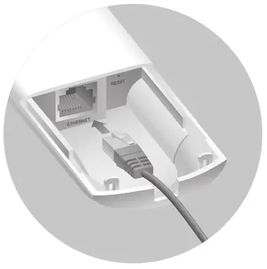
Step 1: Firmly grasp the rear of the interface cover and pull it downward.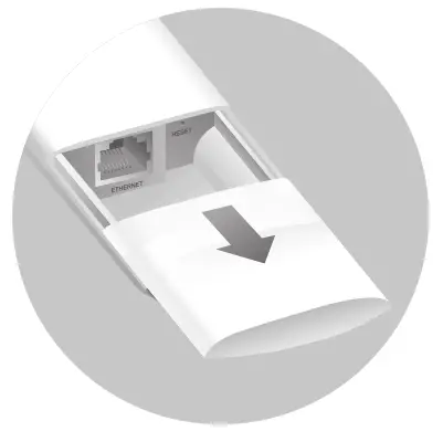 Step 2: Use an adequate Ethernet cable to connect the LAN port. The length of cable is up to 100 m for steady power supply. Shielded CAT5e (or above) cable is recommended.
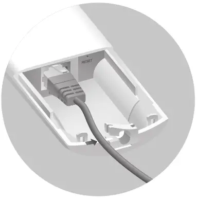
Step 3: Attach the waterproof rubber insert to the groove at the underside of the device for waterproofing. Move the Ethernet cable to the hole of the waterproof rubber insert.
 Step 4: Flatten the waterproof rubber insert until it gets parallel to the device. Replace the cover until it firmly locks into place.
Power On
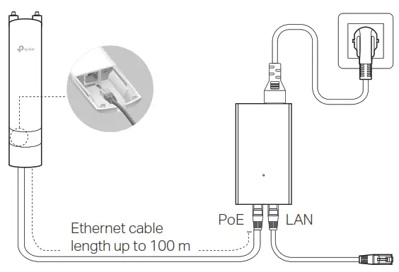
The EAP can be powered via the provided passive PoE adapter or a PSE device (such as a PoE switch). Option 1: Via Passive PoE Adapter Connecting the PoE Adapter Connect the EAP to a Power over Ethernet (PoE) adapter as follows:
Option 1: Via Passive PoE Adapter
Connecting the PoE Adapter
Connect the EAP to a Power over Ethernet (PoE) adapter as follows:
Mounting the PoE Adapter (Optional)
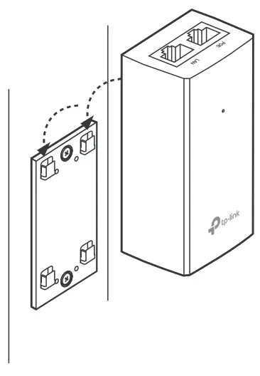
Note: To ensure the passive PoE adapter is attached most securely, it is recommended to install the adapter with the Ethernet port facing upward.
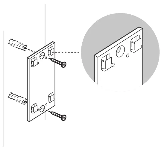
Step 1:
Remove the mounting bracket from the passive PoE Adapter. Drill two holes on the wall and insert the plastic wall anchors into the holes. Secure the mounting bracket to the wall. Make sure the shoulders at the corners of the mounting bracket are on the outside and pointing upward.
 Step 2: Attach the passive PoE adapter to the mounting bracket (for PoE Adapter) by sliding the adapter in the direction of the arrows until it locks into place.
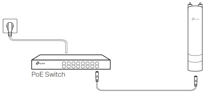
 Option 2: Via PoE Switch (Only for EAP225-Outdoor)
Connect an Ethernet cable from the PoE switch to the Ethernet port.
Software Configuration
A DHCP server (typically a router with DHCP function enabled) is required to assign IP addresses to the EAPs and clients in your local network.
The EAP supports two configuring options:
- To configure and manage EAPs singly (usually suitable for a small network with a few EAPs), Standalone Mode is recommended. Please refer to Option1.
- To configure and manage EAPs in batch, Controller Mode is recommended. Please refer to Option 2.
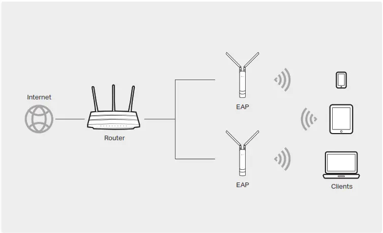
Option1: Standalone Mode
Via Omada App
1. Download the TP-Link Omada App on your mobile device. It can be downloaded from App Store or Google Play:

2. Connect your mobile device to the EAP by using the default SSID (format: TP-Link_2.4GHz/5GHz_XXXXXX) printed on the label at the bottom of the product.
3. Open the Omada App, and wait for the EAP to appear on the Standalone APs page. Tap on the EAP you want to configure.
The Omada App is designed to help you quickly configure the common settings. If you want to configure advanced settings, log in to the web page of your EAP or the controller.
Via a Web Browser
1. Connect wirelessly by using the default SSID (format: TP-Link_2.4GHz/5GHz_XXXXXX) printed on the label at the bottom of the product.
2. Launch a web browser and enter http://tplinkeap.net in the address bar. Use admin for both Username and Password to log in.
3. Set up a new Username and Password for secure management purposes. Modify the wireless parameters and reconnect your wireless devices to the new wireless network.
To configure other EAPs, connect your device to the EAP by the corresponding default SSID and repeat the steps listed above. You can configure some basic functions in Standalone Mode. If you want to configure advanced functions, use Controller Mode.
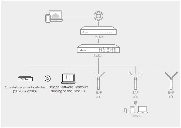
Option2: Controller Mode
Controller Mode is applicable to configuration for mass EAPs. All EAPs can be centrally configured and monitored via Omada Software Controller, Omada Hardware Controller (OC200/OC300), or Omada Cloud-Based Controller.
1. On the PC with Windows OS or Linux OS, download the Omada Software Controller installation file from https://www.tp-link.com/support/download/omada-software-controller/.
2. Run the file and follow the wizard to install the Omada Software Controller.
3. Launch the Omada Software Controller and follow the step-by-step instructions to complete the Quick Setup.
4. After the wizard is finished, a login screen will appear. Enter the username and password you created and click Log in. Then you can further configure the controller. Omada Cloud Service After installing Omada Software Controller, you can remotely access and configure the controller through
Omada Cloud Service. Follow the steps below.
1. Enable Cloud Access on the setting page on the controller and bind a TP-Link ID to your controller. If you have configured this in the setup wizard, skip the step.
2. Launch a web browser and enter https://omada.tplinkcloud.com in the address bar.
3. Enter your TP-Link ID and password to log in. A list of controllers that have been bound with your TP-Link ID will appear. Then you can click Launch to further
configure the controller.
Omada App
With Omada App, you can also manage your Omada Software Controller at a local site and remote site. Note that Omada Software Controller needs to be kept running when using Omada App.
1. Download the TP-Link Omada App on your mobile device. It can be downloaded from App Store or Google Play:
 Scan for Omada App – https://www.tp-link.com/common/app/omada/qrcode.php
2. Launch your Omada App and configure the controller at local a site or remote site.
Local Managementa.
Connect your mobile device to the EAP by using the default SSID (format: TP-Link_2.4GHz/5GHz_XXXXXX) printed on the label at the bottom of the product.
b. Launch Omada App and go to Local Access, tap the + button on the upper-right corner to add the controller. Then you can further configure the controller.
Remote Managementa.
Make sure Cloud Access is enabled on your controller and your controller has been bound with your TP-Link ID.
b. Launch Omada App and log in with your TP-Link ID. Then go to Cloud Access. A list of controllers that have been bound with your TP-Link ID will appear. Then you can further configure the controller.
Via Omada Hardware Controller (OC200/OC300)
Omada Hardware Controller (OC200/OC300), which is pre-installed with Omada Software Controller, is a good alternative if you have no spare PC to keep running Omada Software Controller in the network. It needs to be purchased additionally. For more details, refer to the Installation Guide of OC200/OC300.
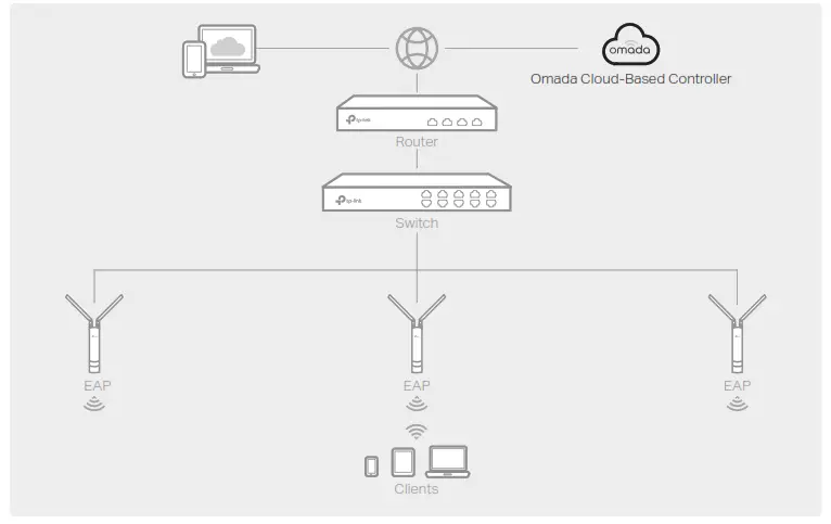
Via Omada Cloud-Based Controller
1. Launch a web browser and enter https://omada.tplinkcloud.com in the address bar. Then enter your TP-Link ID and password to log in.
2. Click Add Controller and subscribe to Omada Cloud-Based Controller. Follow the instructions to choose a plan and complete the payment. Then wait until your controller is deployed.
3. The controller will appear in the list once bound with your TP-Link ID. Click Launch and follow the step-by-step instructions to complete the Quick Setup. After the wizard is finished, log in via the created username and password.
4. Click Devices on the side bar and then click Add Devices. Then you can add devices to the controller manually through the serial numbers at the bottom of the product. Omada App With Omada App, you can also manage your Omada Cloud-Based Controller.
1. Download the TP-Link Omada App on your mobile device. It can be downloaded from
App Store or Google Play:
 2. Launch Omada App and log in with your TP-Link ID. Then go to Cloud Access. A list of controllers that have been bound with your TP-Link ID will appear. Then you can further configure the controller.
Attention:
For EAP225-Outdoor, in EU member states and EFTA countries, the operation in the frequency range 5150MHz-5350MHz is only permitted indoors. For EAP Controller, go to Access Point page and select the desired EAP to specify the channel. For web browser, go to Wireless > Wireless Settings to specify the channel.
| AT | BE | BG | CH | CY | CZ | DE | DE | EE | EL | ES | FI | FR | HR | HU | IE |
| IS | IT | LI | LT | LU | LV | MT | NL | NO | PL | PT | RO | SE | SI | SK | UK |
For detailed configurations, please visit https://www.tp-link.com/support to download the User Guide of EAP in the download center.
 To ask questions, find answers, and communicate with TP-Link users or engineers, please visit https://community.tp-link.com to join TP-Link Community.
 For technical support, the user guide and other information, please visit https://www.tp-link.com/support, or simply scan the QR code.

http://www.tp-link.com/support
 If you have any suggestions or needs on the product guides, welcome to email [email protected].
 Safety Information
Keep the device away from water, fire, humidity, or hot environments. Do not attempt to disassemble, repair, or modify the device. If you need service, please contact us. Do not use the device where wireless devices are not allowed. Do not use any other chargers than those recommended. Adapter shall be installed near the equipment and shall be easily accessible. The products of TP-Link partly contain software code developed by third parties, including software code subject to the GNU General Public License (“GPL”). As applicable, the terms of the GPL and any information on obtaining access to the respective GPL Code used in TP-Link products are available to you in GPL-Code-Centre under (https://www.tp-link.com/en/support/gpl/). The respective programs are distributed WITHOUT ANY WARRANTY and are subject to the copyrights of one or more authors. For details, see the GPL Code and other terms of the GPL.