
Trane Nexia Touchscreen Thermostat Installation Guide andamp; Setup Manual TZEMT524AA21MA
The Trane TZEMT524 Touchscreen Comfort Control is compatible with single and multistage forced air systems,
including:
- Gas furnace systems
- Oil furnace systems
- Electric furnace systems
- Heat pump systems
- Air conditioning systems
The Trane TZEMT524 Touchscreen Comfort Control may be compatible with some other system types, including:
- Boiler systems
- Geothermal systems
- Multi-zoned systems
Call (877) 288-7707 to verify compatibility.
The Trane TZEMT524 Touchscreen Comfort Control is not compatible with the following system types:
- Radiant floor systems
- Wall heating systems

ÎÎNOTE: A 24 Volt common and hot wire MUST be connected to the control for operation.

When this Comfort Control is replacing an old thermostat that contains mercury in a sealed tube, do not dispose of your old thermostat in the trash. Dispose of properly. Contact your local waste management authority for instructions regarding recycling and proper disposal of the old thermostat.
A listing of heating, ventilating and air conditioning wholesalers that participate in the Thermostat Recycling Corporation’s recycling program are available at www.thermostat-recyle.org.
Can cause electrical shock or equipment damage. Disconnect power to heating and cooling equipment before beginning installation.
INSTALLATION GUIDE
1. Prepare for Installation
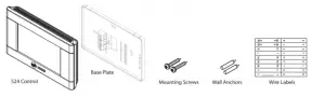
Unpack your new 524 Control and locate the 524 Control, Base Plate, mounting screws, wall anchors and wire labels.
2. Disconnect Power at the Breaker
Located your breaker box and remove or disconnect electrical power to your HVAC system. You may need to disconnect power at both the indoor unit and the outdoor unit.
Failure to remove power can cause electrical shock and/or equipment damage.
3. Remove your existing thermostat cover
Carefully remove the cover of your existing thermostat leaving with wires connected. Consult instructions that came with the existing thermostat as necessary. DO NOT remove the thermostat wires yet.
4. Determine if your system has a 24V common wire connected
- If your system is a heat pump, skip to “6 Label and remove old thermostat wires” on page 3.
- If your existing thermostat has a terminal named C, COM, X or B* with a wire connected to it, skip to “6 Label and remove old thermostat wires” on page 3.
* The B terminal on Trane, American Standard, Weathertron and York thermostats is the 24V Common terminal. On all other thermostats it servers another purpose
5. Connecting a 24V common wire
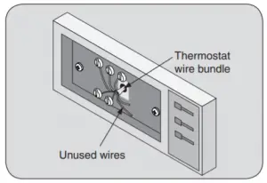
- Locate all unused (disconnected) wires from the thermostat wire bundle and write down the colors. The 24V Common wire is typically (but not always) colored blue.
- Go to your indoor HVAC unit and remove the cover(s) to access the 24 VAC furnace wire terminals
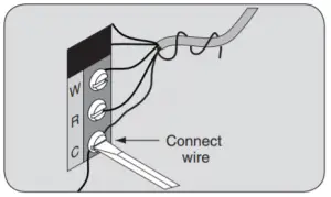
- Find the wiring terminals at the furnace and then identify the 24 VAC common terminal identified with the letter C, X, B, or COM. This terminal may already have a wire connected to it but it may not be a wire that goes to the thermostat.

- Locate the thermostat wire bundle inside the furnace panel. This wire bundle is routed from the thermostat, through the walls, and into the furnace panel. This bundle can be identified at the furnace by checking the wire colors connected and not connected and comparing to the wire bundle at the thermostat.
- Find a wire from the thermostat bundle that is unused at the thermostat and at the furnace.It is possible that one of the unused wires at the thermostat will already be connected to the 24 VAC common terminal at the furnace. If so, go to “6 Label and remove old thermostat wires” on page 3
- Connect the unused wire to the 24 VAC terminal, then replace the furnace cover. The 24 VAC common wire is typically (but not always) blue in color. If the blue wire has been unused, it is recommended that you use the blue wire.
6. Label and remove old thermostat wires
- Label the wires on your existing thermostat to match terminal names.DO NOT USE WIRE COLORS TO CHOSE LABELS. THE TERMINAL NAME IS WHAT IS IMPORTANT.
- Locate the wiring labels included with the new thermostat.
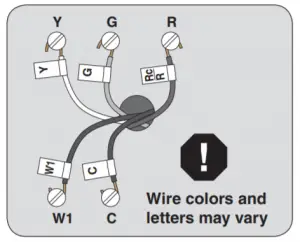
- Observe where each wire is connected to the existing thermostat and find the letter shown next to that wire terminal.
- Attach the corresponding label the wire. IMPORTANT NOTES :If you have a short jumper wire between two terminals, remove the jumper and do not label it. This jumper wire is not required on the new thermostat .If you had to connect a new 24 VAC common wire, you will use the “C” label on that wire.If you have a W terminal, use the W1 label on that wire.If your thermostat has any terminals with names that do not match any on the label, write down the terminal names and wire colors for later reference.

7. Remove existing wall plate.
The 524 Control is designed for installation in climate controlled living spaces. It is recommended to place the unit in a central location with good circulation. Avoid exterior walls and areas near windows, doors, vents or concealed pipes or chimneys .NOTE: DURING THIS PROCESS, MAKE SURE THAT THE WIRES DO NOT PULL BACK INTO WALL OPENING. - Detach all wires from wall plate
- . Remove all screws attaching the wall plate to the wall and remove wall plate
- See “MERCURY NOTICE”.
When this control is replacing a control that contains mercury in a sealed tube, dispose of the old control properly. Contact your local waste management authority for instructions regarding recycling and proper disposal. A listing of heating, ventilating and air conditioning wholesalers that participate in the Thermostat Recycling Corporation’s recycling program are available at www.thermostat-recyle.org
8. Identify your system type
Assuming your existing thermostat is wired correctly, these steps will help you determine what type of equipment is installed in your home. You will use this information when you program your 524 Control.

If you have any questions regarding your system equipment, consult a qualified HVAC professional before proceeding.
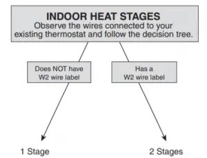
TYPE Your Indoor Heat Stages:

Your Outdoor Unit Type is:
Improper system type selection can lead to equipment damage and/or high utility costs. Follow these instructions to properly determine and select the 524 Control to ensure proper heating and cooling system operation. If you are uncertain about your equipment, please call a qualified HVAC contractor.
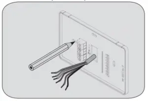
9. Prepare to install the 524 Control
- Separate the 524 Control from the Base Plate by applying pressure to the two tabs at the top of the 524 Control.
NOTE: It is not recommended that this Z-wave™ Control be mounted onto metal structures. Metal may adversely affect the radio frequency (RF) communication between the Control and the Z-wave™ bridge. - Pull the wires through the hole in the center of the 524 Control base plate.
- Mark the position of the two mounting holes on the wall using the 524 Control Base Plate as a template.
- Position the new wall plate over the existing opening.
- Mark the two holes.
- Use a level to verify that the two hole locations are level.
- Correct hole locations as needed.
10. Prepare the mounting holes
- Drill 1/16” pilot holes in the two locations that were marked in step 9. If mounting to drywall with no studs behind it, enlarge pilot holes to 1/8” for anchors.
- If using anchors, screw them into the holes.
11. Attach the new base plate to the wall
- Pull the wires through the hole in center of wall plate.
- Position the new wall plate over the existing opening.
- Attach wall plate to wall using the two screws provided. Do not overtighten.

12. Review the wiring chart information
Refer the chart below to determine which wires connect to the corresponding terminal on the 524 Control.Note than you may have more than one wire connected to a single terminal on the 524 Control.
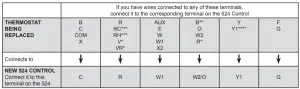
*If your existing thermostat has a “V” or “VR” wire label, connect that wire to “R” on the new thermostat, then connect the wire labeled “R” to
“W2/O/B” on the new thermostat**On thermostats other than Trane. American Standard, Weathertron or York.
***If your existing thermostat has an independent wire connected to the RC terminal and an independent wire connected to the RH terminal, the 524 Control is incompatible with your system.
***If your existing thermostat has a wire connected to the Y2 terminal, the 524 Control is incompatible with your system.
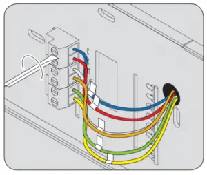
13. Attach all wires securely to the 524 Control
- Note: A wire must be connected to “C” to power the thermostat.
- Use 1/8” blade screwdriver to secure wires in terminals.
Improper wiring can lead to equipment damage. Follow the Terminal Connection information from “12 Review the wiring chart information” on page 5 and carefully to ensure the control is wired properly. After wires are secure, bare wires MUST NOT touch each other.

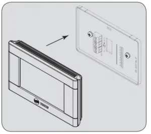
14. Attach the 524 Control face plate to the base plate
- Carefully align the face plate to the wall plate while aligning pins into wire terminals.
- Once 524 Control face is properly aligned, apply pressure at top and bottom of 524 Control face until it is secure.
16. Programming Equipment Settings
Before your 524 Control will operate properly, you must program the equipment settings. Equipment settings are programmed from the Service Menu.
- From the Home Screen, press Menu. Press Next repeatedly until Service is displayed.
- Press and hold Select until Installer Settings is displayed.
- Press Select, Equipment Type is Displayed.
- Press Select. Outdoor Unit Type (with the current selection) is displayed.
- Press Select. Using the up and down arrows, navigate to the type of outdoor unit you have as you determined in “8 Identify your system type” on page 4
- Press Done. Press Next. Indoor Unit Type (with the current selection) is displayed
- Press Select. Using the up and down arrows, navigate to the type of indoor unit you have as you determined in “8 Identify your system type” on page 4.
- Press Done. Press Next. Indoor Heat Stages (with the current selection) is displayed.
- Press Select. Using the up and down arrows, navigate to the number of indoor heat stages you have as you determined in “8 Identify your system type” on page 4.
- Press Done. If you do not have a heat pump, skip the next step
- Press Select. Using the up and down arrows, navigate to the setting that reflects when your heat pump’s reversing valve is energized. Press Done.
- Press Done. You have successfully entered your equipment type and your system should be operational. There are many other settings in the Installer Settings section of the 524 Control that will optimize your system’s performance. The following tables describe all of the available settings and provide a brief description of each.
WHEN YOU HAVE COMPLETED ENTERING THE INSTALLER SETTINGS, YOU WILL FURTHER CUSTOMIZE THE 524 CONTROL WITH USER SETTINGS.
Installer Settings
Installer Settings allow the user to configure the equipment settings and customize how the control operates. To access Installer Settings press the Menu button, then press and hold Next for approximately 5 seconds, until Service is displayed. Now press Select until “Installer Settings” is displayed. Press Select again to enter Installer Settings menu. The default setting will be shown in brackets. After each selection press Done to save changes.
Menu Item: Equipment Type
Setting |
Range |
Description |
| Outdoor Unit Type | None, [AC], HP | Select the type of outdoor unit installed |
| Indoor Unit Type | [Gas/Oil], Electric, Hydronic | Select the type of indoor unit installed |
| Hydronic Type | [With Fan], Without Fan | Select the type of hydronic heat operation. Hydro Air selection interlocks the blower during an active call for indoor heat. Wet Heat selection disables indoor fan operation on an active call for indoor heat. |
| Indoor Heat Stages | [1], 2 | Select the number of indoor heat stages |
| Energize Reversing Valve* | [With Cool], With Heat | Select whether Reversing Valve is energized in cooling or heating mode |
Once all selections have been made, press the Done button to exit and return to Menu. Press Next to navigate to the next setting.
* This setting is typically set to With Cool for systems from Trane, American Standard, Carrier, Lennox and Goodman. It is typically set to With Heat for Rheem/Ruud systems and some systems manufactured in China. If your system delivers heated air when it should deliver cool air, or vice versa, this setting may be reversed.
These settings should only be modified by knowledgeable and experienced individuals familiar with HVAC systems
Menu Item: Equipment Settings |
||
Setting |
Range |
Description |
| Compressor Stage 1 MRT | [3] – 9 Minutes | Select the minimum runtime (MRT) of stage 1 compressor operation |
| Compressor MOT | [5] – 9 minutes | Select the minimum offtime (MOT) for compressor operation |
| Indoor Heat Stage 1 MRT | [3] – 9 Minutes | Select the minimum runtime (MRT) of stage 1 indoor heat |
| Indoor Heat Stage 2 MRT | [3] – 9 Minutes | Select the minimum runtime (MRT) of stage 2 indoor heat |
| Indoor Heat MOT | [5] – 9 minutes | Select the minimum offtime (MOT) for indoor heat operation |
| Once all selections have been made, press the Done button to exit and return to Menu. Press Next to navigate to the next setting. | ||
Menu Item: Sensor Settings |
||
Setting |
Range |
Description |
| Sensor Calibration | *-7 – +7 Degrees [0] | Calibrate the indoor temperature sensor (do not attempt to calibrate the indoor temperature within the 1st hour upon power-up) |
| Once all selections have been made, press the Done button to exit and return to Menu. Press Next to navigate to the next setting. | ||
Menu Item: Comfort Settings |
||
Setting |
Range |
Description |
| Comp Heat Delta Stage 1 On | . 5 – 8 Degree | Select the delta on for 1st stage compressor heat |
| Indoor Heat Delta Stage 1 On | 5 – 8 Degree | Select the delta on for 1st stage indoor heat |
| Indoor Heat Delta Stage 2 On | 1 – 8 Degree | Select the delta on for 2nd stage indoor heat |
| Comp Heat Delta Stage 1 Off | 0 – 8 Degree | Select the delta off for 1st stage compressor heat |
| Comp Heat Delta Stage 2 Off | 0 – 8 Degree | Select the delta off for 2nd stage compressor heat |
| Indoor Heat Delta Stage 1 Off | 0 – 8 Degree | Select the delta off for 1st stage indoor heat |
| Indoor Heat Delta Stage 2 Off | 0 – 8 Degree | Select the delta off for 2nd stage indoor heat |
| Cooling Delta Stage 1 On | .5 – 8 Degree | Select the delta on for 1st stage cooling |
| Cooling Delta Stage 1 Off | (-) 2 – (+)6 | Select the delta off for 1st stage cooling |
| Recovery Enable | Yes, [No] | When enabled, will start the cooling or heating system so that the desired comfort temperature is reached by the next scheduled set point time. The advance start time calculation is a learned process that is recalculated and adjusted each day until the room temperature is at the target temperature at the schedule time. When the thermostat is in Recovery mode the display will show “Recov”. While in Recovery the Aux-Heat stage will not engage. The maximum Recovery time is one hour. |
| Once all selections have been made, press the Done button to exit and return to Menu. Press Next to navigate to the next setting. | ||
Menu Item: Airflow Settings |
||
Setting |
Range |
Description |
| Blower On Delay Cooling | [0] – 30 seconds | (Non-Variable Speed blower only) Select the cooling blower on delay |
| Blower Off Delay Cooling | [0] – 90 Seconds | (Non-Variable Speed blower only) Select the cooling blower off delay |
| Blower On Delay Heating | [0] – 30 Seconds | (Non-Variable Speed blower only) Select the compressor heating blower on delay |
| Blower On Delay Heating | [0] – 60 Seconds | Select the hydronic heating blower on delay |
| Blower Off Delay Heating | [0] – 90 Seconds | (Non-Variable Speed blower only) Select the compressor heating blower off delay |
| Blower Off Delay Heating | [0] – 90 Seconds | Select the hydronic heating blower off delay |
| Once all selections have been made, press the Done button to exit and return to Menu. Press Next to navigate to the next setting. | ||
Restore Defaults
Restore Defaults is used to restore the control to factory default settings. To access “Restore Defaults” press the “Menu” button, then press and hold “Next” for approximately 5 seconds, until Service” is displayed. Now press Select until “Installer Settings” is displayed. Press Next until “Restore Default” is displayed. Now press Select again to enter “Restore Default”. The default setting will be shown in brackets. After each selection press Done to save changes.
Menu Item: Restore Defaults |
||
Setting |
Range |
Description |
| Restore Default | Yes, [No] | Select “Yes” to restore all the User and Installer settings to the factory defaults. If “Yes” is selected “Restoring” will be displayed. “Done” will be displayed once all settings have been restored. |
| Note: To reset all User, Installer and Z-Wave settings, press and hold the “Yes” button for 5 seconds. Release when “Factory Defaults” is displayed. “Done” will be displayed once all settings have been restored and the control will automatically return to the home screen.. | ||
Operation
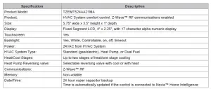
The model TZEMT524AA21MA Comfort Control provides typical operation of a forced air heating and cooling HVAC system. The control also features a Z-Wave™ module for remote control when connected to Nexia™ Home Intelligence.
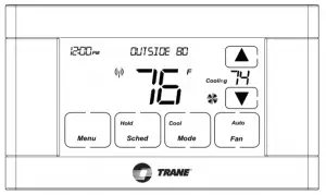
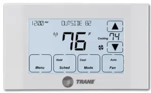
Normally, the 524 Control displays the Home Screen as shown above
Item |
Description |
Notes |
| Clock Display | The current time is displayed in the upper left corner of the main screen. The time will blink when the clock has not been set. | See TIME/DATE for more information. If the Control is connected to Nexia™ Home Intelligence, the clock will be updated automatically. |
| Dynamic Labels and Function Control Buttons | The buttons are defined by the dynamic labels in each button. As you navigate through menus, the labels for the buttons will change. | See TIME/DATE for more information. If the Control is connected to Nexia™ Home Intelligence, the clock will be updated automatically. |
| Setpoint Display and Setpoint Up/Down Buttons | The current heating or cooling setpoint is displayed. These setpoints may be set using Nexia™ Home Intelligence, the Control’s internal schedule, or by pressing the Setpoint Up/Down buttons. Pressing the setpoint button changes the setpoint screen. The current mode is displayed at the top of the screen. Adjust the setpoint by pressing the up or down arrows. To change setpoint mode press the MODE button. | The heating and cooling setpoints will push each other if they are adjusted to within the minimum heat/cool separation setting. The default is 3 degrees. |
| Temperature Display | The 524 Control displays the current temperature as sensed by the internal temperature sensor. | The internal temperature sensor offset can be adjusted if necessary. |
| MENU Button | Press to access other menus | Other menus can be accessed by pressing the MENU button. |
| SCHED Button | Press to change the schedule mode | Hold: System maintains the current temperature setpoints and schedules are disregarded. Run: Run the system schedule Energy Saving Mode (ESM): Temperature setpoints selected in ESM are maintained. |
| MODE Button | Press to change the system mode | Off: System off Heat: Heating only Cool: Cooling only Auto: Heating/Cooling as necessary |
| FAN Button | Press to change the fan mode | Auto: Fan is on when cooling/heating is necessary On: Fan constantly on Circ: Fan is on for a user-selected number of minutes per hour. |
User Settings
User Settings allow the user to customize various settings on the 524 Control. To access User Settings simply press Menu and SELECT. Use the NEXT and BACK buttons to navigate through the options. Use the SELECT button to enter change mode. After making your changes, use the DONE button to register your changes. The various options are shown in the following tables, and the default setting is shown in brackets.


Schedule
The 524 Control features a 7-day programmable schedule, and each day can 4 unique periods (Wake, Day, Eve and Night). Each day of the week is set independently and the Copy Schedule function allows you to copy a schedule, once set, from one day to one or more other days of the week.
Note: If the Schedule menu does not appear, be sure that Local Scheduling is enabled. This setting is accessed from the User Settings: Thermostat: Local Schedule Enable.
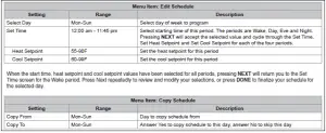
Programming a Schedule for one day
13. From the Home Screen press MENU, then press NEXT until Schedule appears at the top of the screen.
14. Press SELECT, Edit Schedule appears at the top of the screen, press SELECT again.
15. Press NEXT or BACK until the desired day of the week is displayed. Press SELECT.
16. Using the up and down arrows, select the time of day for the Wake period to begin. Press NEXT.
17. Using the arrows, select the desired heating setpoint. Press NEXT. Now select the desired cooling setpoint and press NEXT.
18. Continue this process for the Day, Eve and Night periods, pressing NEXT each time after you have selected the desired values.
19. After you have selected the Night cooling setpoint, the display cycles back to the Wake time of day setting. To verify your selections, press NEXT repeatedly to cycle through your selections, making changes as necessary. When you are satisfied with your schedule, press DONE. You now see the Copy Schedule screen. Skip to step 3 below.
Copying a Schedule from one day to one or more days
- From the Home Screen press MENU, then press NEXT until Schedule appears at the top of the screen.
- Press NEXT or BACK until Copy Schedule appears at the top of the screen. Press SELECT.
- Press NEXT or BACK until the desired day is displayed. This is the “from” day and will be a day for which you previously programmed a schedule.
- Press SELECT.
- Press YES to copy the schedule to this day, or NO to skip this day. Cycle through the days of the week until your selection is complete
- Press DONE to complete the copying process. Press DONE again to return to the User Settings menu.
Edit Schedule from the Nexia web portal
Schedules can be easily updated from your Nexia™ Home Intelligence account. Simply go to www.MyNexia.com, log into your account and select a TZEMT524 comfort control from the Climate Page. Click on Edit Schedule and follow the online instructions.
If you have not set up a Nexia™ Home Intelligence account go to www.MyNexia.com and click on “Get Started”. A router and Nexia Bridge are required for remote access to the 524 Control. For questions about connecting, contact Nexia™ Home Intelligence Customer Service at 877-288-7707
1. Prepare the Nexia Bridge for enrollment .
Note: The Nexia Bridge is purchased separately. If the Bridge is not installed, follow the instructions that were included with the Nexia Bridge. If the Bridge is already installed, follow the instructions as they are written in the following steps.
- Unplug Ethernet and power cables from bridge
- Install a fully-charged, quality 9 volt battery.
- Verify that blue light is blinking. If blue light is solid, the battery is dead.
- Take the Bridge to the location where the 524 Control is mounted.

2 Enroll the 524 Control into the Bridge. (Inclusion)
that shipped with the controller to find out how to enroll a new device.
If you are using a controller that is not a Nexia™ bridge, consult the instructions that shipped with the controller to find out how to enroll a new device.
- Hold the Bridge within 6 feet (1.8 meters) of the 524 Control throughout this process.� After you begin the enrollment process, you have 30 seconds to complete the remainder of the steps. Study the steps below before beginning
- Press and release the plus (+) button on the bridge.
- Press MENU on the 524 Control.
- Press NEXT to advance to the Z-WAVE menu.
- Press SELECT.6. Observe the lights on the bridge. The orange light will blink while enrollment is taking place. Enrollment is complete when the orange light becomes solid.

3. Verify enrollment of the 524 Control
- Press MENU from the 524 Control Home screen.
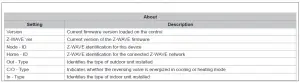
- Press NEXT to advance to the About screen and press SELECT.
- Press NEXT to advance through the menu options to Node ID.
• If the number listed there is anything other than “00”, the 524 Control has been successfully enrolled.
• If the number listed there is “00”, the 524 Control has NOT been successfully enrolled. In this case, restart the process beginning with Step 2 - Press DONE twice when finished.
4. Configure the 524 Control for Nexia
A Nexia™ Home Intelligence account must be active before continuing. See www.nexiahome.com for more information.
- Remove the battery from the Bridge.
- Plug the Ethernet and power cord back into the Bridge.
- Log into your account at www.mynexia.com4. Click the Climate tab. Locate the new 524 Control and follow the on screen instructions.
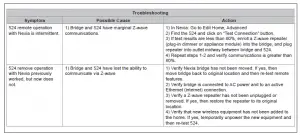
Note: If the new thermostat icon remains gray or cannot be controlled remotely, you might need to add Z-wave repeaters to improve communications. Contact your local Nexia expert or call 877-288-7707 for assistance.
Note: From time to time, firmware updates for your 524 Control may be placed in your Nexia account. To check for available updates, log in to your Nexia account and click on the Edit Home button. Next, click on the Firmware Updates button and follow the on screen instructions.
Menu Item: Exclude from Net
If you need to remove the 524 Control from a Nexia™ Home Intelligence account, follow these exclusion steps. This will disable remote access. If you are unsure, please contact Nexia support at 877‑288‑7707.
Install a fully charged, quality 9-volt battery into the Bridge.
- Hold the Bridge within 6 feet (1.8 meters) of the 524 Control throughout the entire exclusion process. After you begin the exclusion process, you have 30 seconds to complete the remainder of the steps. Study the steps below before beginning
- Press and release the minus (-) button on the bridge
- Press MENU on the 524 Control.
- Press NEXT to scroll to Z-WAVE screen then press SELECT
- Press YES to exclude the control
- Observe the lights on the Bridge. The orange light will blink while exclusion is taking place. Exclusion is complete when the orange light becomes solid.
-Wave™ controllers from various manufacturers may support the Z-Wave™ Thermostat General V2 Device class used by the Z-Wave™ control. If you are using a controller that is not a Nexia bridge, consult the instructions that came with the controller to find out how to enroll and exclude devices.
Installer Settings
Installer settings are described earlier in this document.
About
Clean Screen

Troubleshooting

USER GUIDE
Features
TZEMT524AA21MA Comfort Control Features
- 24v, Z-Wave comfort control
- Remote access via smart phone, tablet, or P.C. (requires a Nexia bridge, Internet access and a Nexia™ Home Intelligence account).
- Interactive 4.3” touchscreen
- 7 Day programmable, 4 periods/day
- Filter and maintenance service reminders
- Energy Savings Mode (ESM)
- Screen lock and guest lock
- Upgradable firmware (requires a Nexia™ Home Intelligence account).
Product Specifications
Trane Remote Energy Management Thermostat
Limited One (1)-Year Electronics and Mechanical Warranty
U.S.A. and Canada Only
Subject to the terms and conditions of this Limited One (1)-Year Electronics and Mechanical Warranty, Trane warrants that, if within one (1) year from Original Date of Purchase, the Purchased Product fails due to defect in manufacture, material or workmanship, Trane will provide a replacement for the Purchased Product or refund the Original Purchase Price, at its sole option, to the Original Purchaser occupying the premises in which the Purchased Product was originally installed. This warranty applies to the Original Purchaser only and is non-transferable. The one (1)-year limited warranty period begins from Original Date of Purchase, confirmed by sales receipt or other dated proof of purchase
Exclusions: The following costs, expenses and damages are not covered by the terms and conditions of this One(1)-Year Limited Electronics and Mechanical Warranty: (i) labor and costs including, but not limited to, original initial installation, removal and reinstallation of Purchased Product; (ii) shipping and freight expenses for any required return of Purchased Product; (iii) failures, defects, or damages (including, but not limited to, any security failure or loss of data) caused by any third party product, service, or system connected or used in conjunction with the Purchased Product; and (iv) any other incidental, consequential, indirect, special and/or punitive damages, whether based on contract, warranty (express or implied), tort (including, but not limited to, strict liability or negligence), patent infringement, or otherwise, even if advised of the possibility of such damages. Additionally, this limited warranty does not cover scratches, abrasions, or deterioration due to the use of paints, solvents or other chemicals.
Further, the terms and conditions of this One (1)-Year Limited Electronics and Mechanical Warranty do not apply to Purchased Product when: (1) used in common area applications (2) used for purposes for which it was not designed or intended; (3) subjected to alteration, modification, abuse, misuse, negligence or accident, improper storage, improper installation or maintenance or operation or unauthorized repair; (4) used in violation of written instructions provided for Purchased Product; (5) subjected to improper temperature, humidity or other environmental conditions; or (6) damaged as a result of acts of God
This One (1)-Year Limited Electronics and Mechanical Warranty is the only express warranty Trane makes on this product. THE DURATION OF ANY IMPLIED WARRANTIES, INCLUDING THE WARRANTIES OF MERCHANTABILITY AND FITNESS FOR A PARTICULAR PURPOSE, IS HEREBY LIMITED TO THE ONE-YEAR DURATION OF THIS WARRANTY. IF THIS PURCHASED PRODUCT IS CONSIDERED A CONSUMER PRODUCT, SOME STATES DO NOT ALLOW THE EXCLUSION OR LIMITATION OF INCIDENTAL OR CONSEQUENTIAL DAMAGES, SO THIS LIMITATION MAY NOT APPLY TO YOU. REFER TO YOUR LOCAL LAWS FOR YOUR SPECIFIC RIGHTS UNDER THIS WARRANTY.
Additional items: Trane does not authorize any person to create for it any obligation or liability in connection with the Purchased Product. Trane’s maximum liability hereunder is limited to the Original Purchase Price of the Purchased Product. No action arising out of any claimed breach of this warranty by Trane may be brought by the Original Purchaser more than one (1) year after the cause of action has arisen.
If you have a claim under this warranty, please return the Purchased Product to place of purchase for replacement or refund of the Original Purchase Price in exchange for the return of the Purchased Product, including sales receipt or other dated proof of purchase. Contact Nexia Home Intelligence Customer Service at 877-288-7707 in U.S.A. and Canada for assistance with set-up and installation, or questions regarding your warranty claim.
FCC Compliance Statement
FCC Compliance Statement
Models XL624, Silver XM, XR524
FCC ID: WIBTZW012 IC: 9374A-XR624
This device complies with Part 15 of the FCC Rules. Operation is subject to the following two conditions: (1) This device may not cause harmful interference, and (2) This device must accept any interference received, including interference that may cause undesired operation.
This equipment has been tested and found to comply with the limits for Class B Digital Device, pursuant to Part 15 of the FCC Rules. These limits are designed to provide reasonable protection against harmful interference in a residential installation. This equipment generates and can radiate radio frequency energy and, if not installed and used in accordance with the instructions, may cause harmful interference to radio communications. However, there is no guarantee that interference will not occur in a particular installation. If this equipment does cause harmful interference to radio or television reception, which can be determined by turning the equipment off and on, the user is encouraged to try to correct the interference by one or more of the following measures.
- Reorient or relocate the receiving antenna
- Increase the separation between the equipment and receiver
- Connect the equipment into an outlet on a circuit different from that to which the receiver is connected
- Consult the dealer or an experienced radio/TV technician for help
Any changes or modifications not expressly approved by the party responsible for compliance could void the user’s authority to operate the equipment
IC 9374A-XR624
This device complies with Industry Canada license-exempt RSS standard(s). Operation is subject to the following two conditions: (1) this device may not cause interference, and (2) this device must accept any interference, including interference that may cause undesired operation of the device.