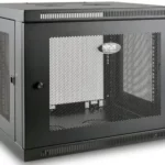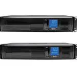
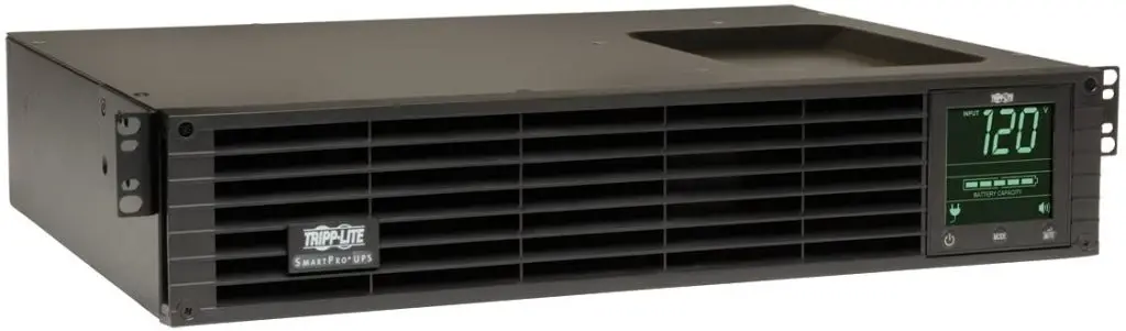
TRIPP LITE SmartPro 2U Rackmount

Important Safety Instructions
SAVE THESE INSTRUCTIONS
This manual contains important instructions that should be followed during the installation, operation and storage of this product. Failure to heed these warnings may affect the warranty.
UPS Location Warnings
• Use caution when lifting the UPS. Because of the considerable weight of all rackmount UPS systems, at least two people should assist in lifting and installing them.
• Install the UPS indoors, in an area free from excess moisture, heat, dust, conductive contaminants, and direct sunlight.
• The UPS operating temperature is 32° to 104°F (0° to 40°C). For optimum battery performance, the ambient temperature should be maintained between 68° and 77°F (20° and 25°C).
• Leave adequate space around all sides of the UPS for proper ventilation. Do not obstruct its vents or fan openings.
• When mounting the UPS system in tower orientation, make sure the LCD Screen panel is at the top of the UPS, not at the bottom.
• Do not mount unit with its front or rear panel facing down (at any angle). Mounting in this manner will seriously inhibit the unit’s internal cooling, eventually causing product damage not covered under warranty.
• The UPS must be returned to Tripp Lite for battery replacement. Visit www.tripplite.com/support and click the product returns link to request a Returned Material Authorization (RMA) number (an RMA number is required for servce). Once the product request information is completed, an assigned RMA number and shipping instructions will be sent to your email account. See Storage and Service for more information.
UPS Connection Warnings
• The UPS contains its own energy source (battery). The output terminals may be live even when the UPS is not connected to an AC supply.
• Connect the UPS to a properly grounded AC power outlet. Do not modify the UPS system’s plug in a way that would eliminate its connection to ground. Do not use adapters that eliminate the UPS system’s connection to ground.
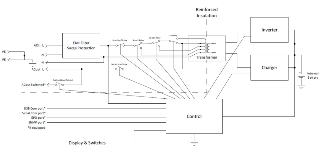
• This UPS is designed to be used on a power distribution system in accordance with the plug configuration. The basic circuit operation is as follows:
- Do not plug the UPS into itself; this will damage the UPS and void the warranty.
- If connecting the UPS to a motor-powered AC generator, the generator must provide filtered, frequency-regulated computer-grade output. Connecting the UPS to a generator will void its Ultimate Lifetime Insurance.
Equipment Connection Warnings
- Use of this equipment in life support applications where failure of this equipment can reasonably be expected to cause the failure of the life support equipment or to significantly affect its safety or effectiveness is not recommended.
- Do not connect surge protectors or extension cords to the output of the UPS. This might damage the UPS and may affect the surge protector and UPS warranties.
Battery Warnings
- Batteries can present a risk of electrical shock and burn from high short-circuit current. Observe proper precautions. Do not dispose of the batteries in a fire. Do not open the UPS or batteries. Do not short or bridge the battery terminals with any object. There are no user-serviceable parts inside the UPS. At the end of the UPS unit’s life, follow best practice by discharging the battery prior to disposal. Refer to local codes for disposal requirements. Do not connect or disconnect battery packs when the UPS is operating on battery power.
- Do not operate the UPS without batteries.
Fan Replacement Warning
The cooling fan installed in the UPS can be replaced by qualified service personnel. Always unplug and turn off the UPS before performing fan replacement. Use tools with insulated handles. Refer to the Fan Replacement section for step-by-step instructions.
Connecting the Battery
The UPS is shipped with the battery disconnected. The battery must be connected for the UPS to operate; this should be done prior to connecting the UPS to AC mains or connecting any equipment to the UPS. Follow the installation procedure below:
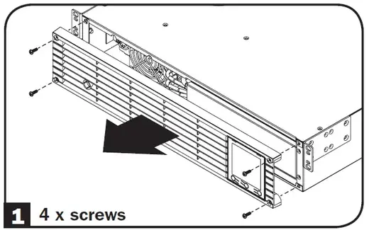
Remove Front Panel.
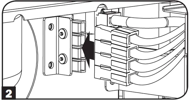
Connect Batteries.
Attach both sets of connectors as shown: black-to-black and red-to-red.
Always ensure that the battery terminals are properly secured.
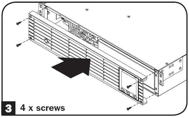
Replace Front Panel.
Quick Installation
The UPS batteries must be fully charged (minimum 24 hours) before plugging equipment into the unit.
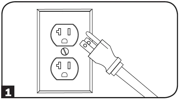
Plug the UPS into an outlet on a dedicated circuit.
NOTE! after plugging the UPS into a live AC outlet, the UPS (in “Standby” mode) will automatically charge its batteries, but will not supply power to its outlets until it is turned ON.
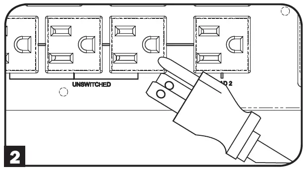
Plug the equipment into the UPS.*
The UPS is designed to support only electronic equipment. If the total VA rating for all connected equipment exceeds the UPS output capacity, the UPS will indicate an overload alert. To find the equipment’s VA rating, look on its nameplate. If the equipment is listed in amps, multiply the number of amps by 120 to determine VA. (Example: 1 amp × 120 = 120 VA). To confirm the UPS outlets are not overloaded, see the LOAD icon description in the LCD Interface section under Basic Operation.
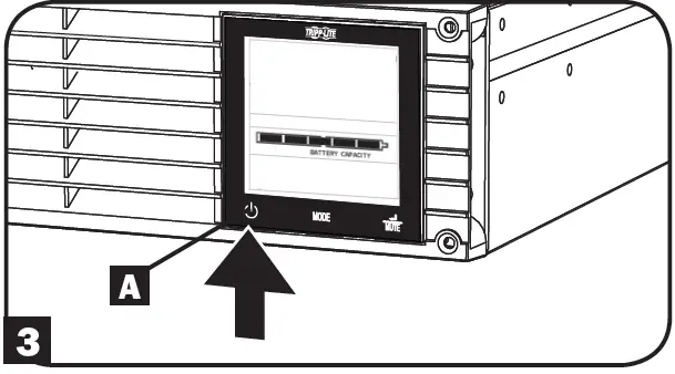
Turn the UPS ON.
Press and hold the button A for one second. The alarm will beep once briefly.
Mounting (Rack)
Mount the UPS in either a 2-post or 4-post rack or rack enclosure. The user must determine the fitness of hardware and procedures before mounting. If hardware and procedures are not suitable for the application, contact the manufacturer of the rack or rack enclosure. The procedures described in this manual are for common rack and rack enclosure types and may not be appropriate for all applications.
2-Post Mounting
2-post mounting requires a Tripp Lite 2-Post Rackmount Installation Kit (model: 2POSTRMKITWM, sold separately).
Post Mounting
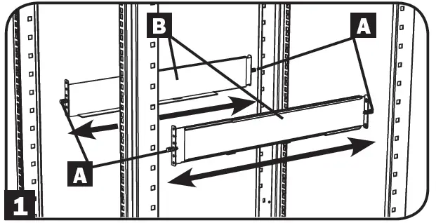
The included plastic pegs A will temporarily support the empty rackmount shelves B while the permanent hardware is installed. Insert a peg near the center of the front and rear bracket of each shelf as shown. (Each front bracket has 6 holes and each rear bracket has 3 holes.) The pegs will snap into place.
After installing the pegs, expand each shelf to match the depth of the rack rails. The pegs will fit through the square holes in the rack rails to support the shelves. Refer to the rack unit labels to confirm that the shelves are level in all directions.
Note: The support ledge of each shelf must face inward.
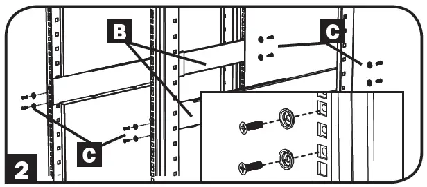
Secure the shelves B to the mounting rails permanently using the included screws and cup washers C as shown. Place the cup washer between the screw and the rack so that the screw enters the wider opening of the cup washer first. Place 4 screws total at the front and 4 screws total at the back. Tighten all screws before proceeding.
Warning: Do not attempt to install the UPS until the required screws are inserted and tightened. The plastic pegs will not support the weight of the equipment.
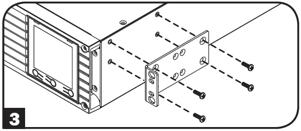
Attach the UPS mounting brackets to the forward mounting holes of the cabinet using the hardware included with the UPS. The mounting bracket “ears” should face forward. (Some equipment may have pre-installed or integrated mounting brackets.)
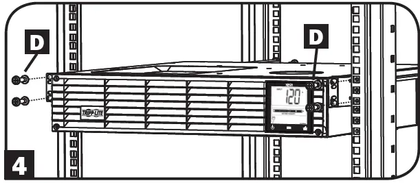
With the aid of an assistant (if necessary), lift the UPS and slide it into the shelves. Attach the equipment mounting brackets to the forward mounting rails with user-supplied screws and washers D. Tighten all screws securely.
Mounting (Tower)
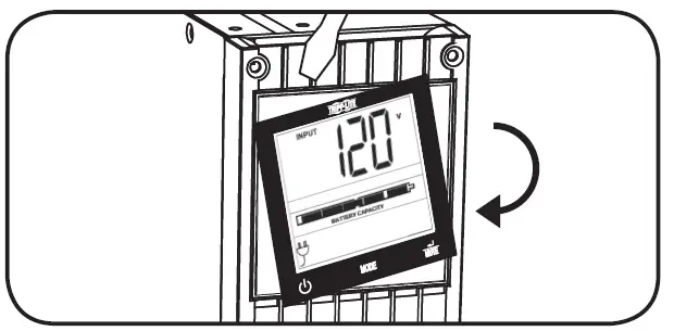
Warning: When mounting the UPS system in a tower orientation, make sure the LCD Screen panel is at the top of the UPS, not at the bottom.
Note: To mount the UPS in an upright (tower) position, 2-9USTAND is required (sold separately).
Rotate the LCD Screen panel for easy viewing while the UPS is tower mounted. Insert a small screwdriver or other tool in the slots on either side of the panel. Pop the panel out, rotate it and pop the panel back in place.
Optional Installation
These connections are optional. The UPS will function properly without these connections.
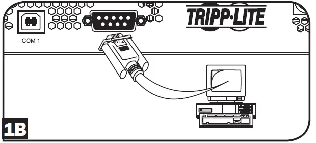
USB and RS-232 Serial Communications
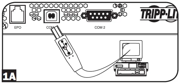
Use the included USB cable (see 1A ) or DB9 serial cable (see 1B ) to connect the communication port on the computer to the communication port of the UPS. Install the appropriate Tripp Lite PowerAlert® Software to the computer’s operating system.
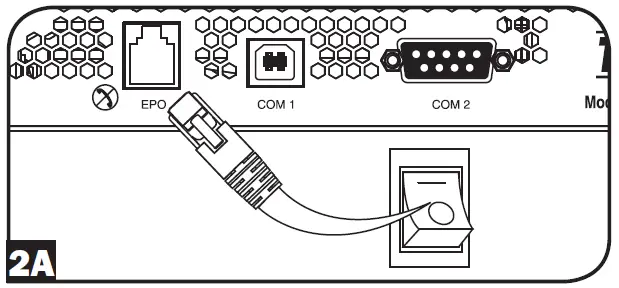
EPO Port Connection
This optional feature is only for those applications which require connection to a facility’s Emergency Power Off (EPO) circuit. When the UPS is connected to this circuit, it enables emergency shutdown of the UPS inverter.
Using the cable provided, connect the EPO port of the UPS (see 2A ) to a user-supplied normally closed or normally open switch according to the circuit diagram (see 2B ). The EPO port is not a phone line surge protector; do not connect a phone line to this port.
UPS Operating Modes
Standby Mode
(Charger: ON / AC Output: OFF / Battery Backup: NOT AVAILABLE)
When first connected to a live power source, the UPS will automatically energize into STANDBY MODE. In this mode, the UPS charger will function as necessary to maintain full battery charge, but there will be no AC output and no battery backup for connected equipment in the event of a power failure. To turn the UPS on into LINE POWER MODE, press and hold the “ON/OFF” button for one second until a beep is heard, and release.
Line Power Mode
(Charger: ON / AC Output: ON / Battery Backup: AVAILABLE)
The standard protected UPS operating mode for the UPS is LINE POWER MODE. In this mode, the UPS provides voltage-regulated output sourced directly from the AC mains line power input. UPS output power is conditioned with automatic voltage regulation in LINE POWER MODE to correct any voltage fluctuations present on the mains line power input. When operating in LINE POWER MODE, the UPS will automatically switch to BATTERY MODE during power failures or severe voltage fluctuations to maintain connected equipment operation from battery reserves.
Battery Mode
(Charger: OFF / AC Output: ON / Battery Backup: ON)
BATTERY MODE is the automatic UPS response to mains AC power failures and severe voltage fluctuations occurring when the UPS is operating in LINE POWER MODE. In BATTERY MODE, the UPS is providing battery-derived AC output to connected equipment. When running in BATTERY MODE, the UPS will automatically return to LINE POWER MODE when acceptable mains AC input is restored to the UPS.
Basic Operation
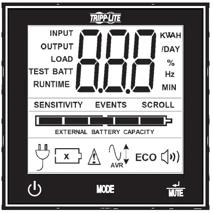
LCD Interface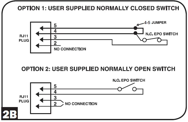
Note: This LCD image is shown with all icons illuminated. Under normal conditions, only select icons will be lit.
3-Digit Display: This display is generally used to show values for a given “Display” or “Control” screen.
“ON/OFF” Button
To turn the UPS ON: After plugging the UPS into a live AC outlet, the UPS (in ”Standby” mode) will automatically charge its batteries, but will not supply power to its outlets until it is turned ON. With the UPS plugged into a live AC wall outlet, press and hold the “ON/OFF” button for one second.* The UPS will beep once to indicate ON status. Release the button.
To turn the UPS OFF: With the UPS ON and receiving utility power, press and hold the “ON/OFF” button for 2.5 seconds.* The UPS will beep once to indicate OFF status. Then unplug the UPS from the wall outlet. The UPS will be completely OFF.
If the user unintentionally presses the ON/OFF button, the OFF function can be temporarily canceled by continuing to hold the ON/OFF button until the UPS beeps and then momentarily pressing either the MODE button or the ENTER/MUTE button. Once both buttons are released, the UPS will remain ON.
“MODE” Button
To enable viewing of power displays and control menu options, tap this button. See “Display Power Conditions” & “Control Menu Options” for details.
• May be used in conjunction with the ON/OFF button to cancel the “OFF” function. See “ON/OFF Button” instructions above.
• May be used in conjunction with the ENTER/MUTE button to restore the LCD to Factory Mode. See “Control Menu Options”.
Basic Operation
ENTER/MUTE” Button
To toggle settings options while viewing a control menu option, tap this button. The UPS power failure alarm can also be temporarily silenced by tapping this button. Once silenced, an alarm will automatically re-sound to indicate low battery conditions and can no longer be silenced.
- May be used in conjunction with the ON/OFF button to cancel the “OFF” function. See “ON/OFF Button” instructions.
- May be used in conjunction with the ENTER/MUTE button to restore the LCD to Factory Mode. See “ON/OFF Button” instructions.
Note: Alarm-free silent operation is available by setting the alarm to disable (see Control Menu Options / Alarm Enable-Disable section).
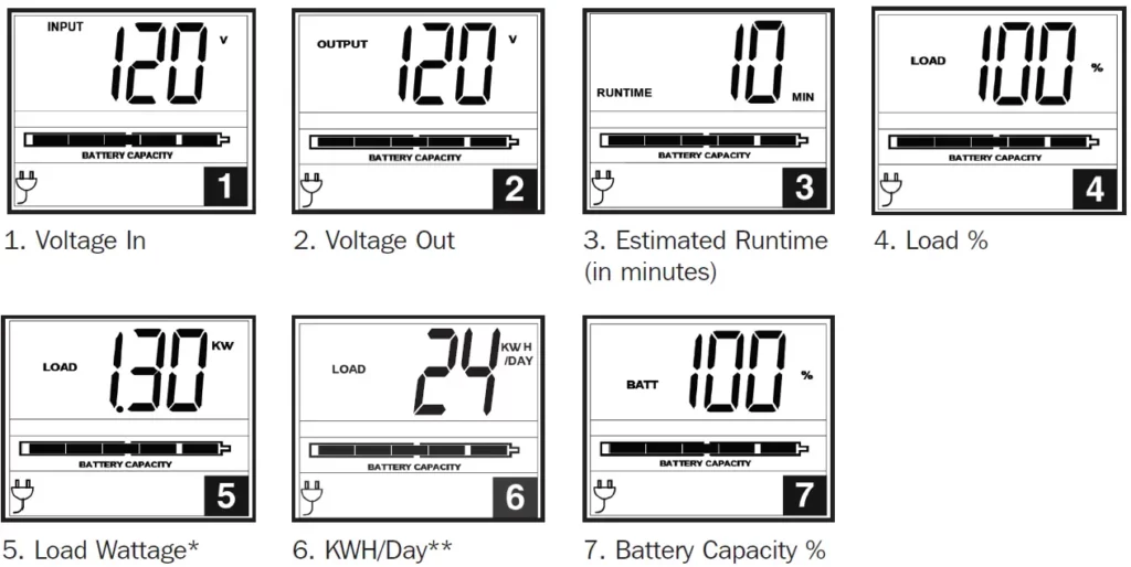
Battery Capacity: This will be active in all “Display” modes, and is not shown in “Control” modes.
AC Input: This indicates the unit is running in Line Mode and supplying AC power to equipment connected to the output.
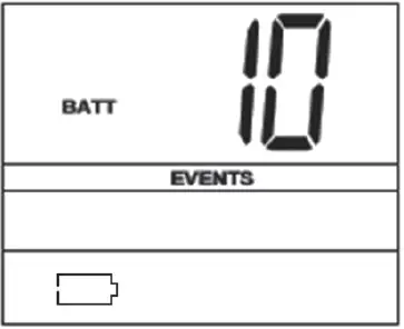
Battery Input: This will flash to indicate the UPS is not receiving AC input and is running in inverter mode. The Battery Input icon is also used in conjunction with the EVENTS icon to indicate On Battery events.
Replace Battery Icon: In the event that UPS batteries expire and require replacement, this icon and the warning icon will flash (see Battery Warnings section for details).
Note: This icon will also flash after a failed UPS self-test (see the Basic Operation / Control Menu Options / Self-Test section for more information).
Warning: This will flash to let the user know there’s a warning condition and immediate action must be taken:
- For Replace Battery: Replace Battery and Warning icons flash during any normal “Display” mode.
- For Overload: Load, Warning and Load Percentage icons will flash, the alarm will sound repeatedly and the LCD screen will switch from the user-selected display mode to Load Percentage. Overload indication is available in both AC and battery modes. CAUTION! Any overload condition that is not corrected by the user immediately may cause the UPS to shut down and cease supplying power in the event of a blackout or brownout.
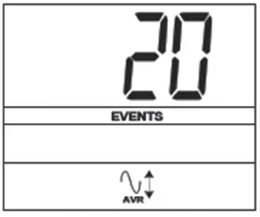
EVENTS Icon: Displayed in conjunction with the AVR icon and BATT icons to indicate the number of On Battery or AVR events that have occurred.
Alarm Off: Indicates the alarm is disabled.
Alarm On: Indicates the alarm is enabled.
INPUT Icon: Indicates the 3-digit value displayed is the Input Voltage.
OUTPUT Icon: Indicates the 3-digit value displayed is the Output Voltage.
LOAD Icon: Displayed in two modes:
1. Displayed in conjunction with the % icon and 3-digit value to indicate the load percentage.
2. Displayed in conjunction with KWH/Day and 3-digit value to indicate daily power consumption.
3. Both the LOAD icon and Warning icon will flash to indicate an overload.
BATT Icon: Displayed in two modes:
- BATT icon (displayed in conjunction with % icon and 3-digit value) indicates the Battery Capacity %.
- BATT icon is shown with TEST icon to indicate self-test mode or control mode.
% Icon: Indicates units of %.
TEST Icon: Displayed in conjunction with BATT icon to indicate the UPS is performing a self-test.
RUNTIME Icon: Displayed in conjunction with the MIN icon and 3-digit value to indicate Runtime in minutes.
MIN Icon: Indicates units of minutes.
- Displayed in conjunction with RUNTIME icon and 3-digit value to indicate battery runtime in minutes.
- Displayed in conjunction with the 3-digit value (reporting “LCD”) to indicate the minimum brightness.
VWA Icon: This is a multipurpose icon which indicates units of Volts, VA, Watts, or Amps (V, VA, W, or A will be shown).
K Icon: Displayed in conjunction with the W to indicate Kilowatts. It is also used in conjunction with the WH and /DAY icons to indicate Kilowatt Hours per Day.
H and /DAY Icons: Displayed in conjunction with “K” and “W” icons to indicate Kilowatt Hours per day (KWH/DAY).
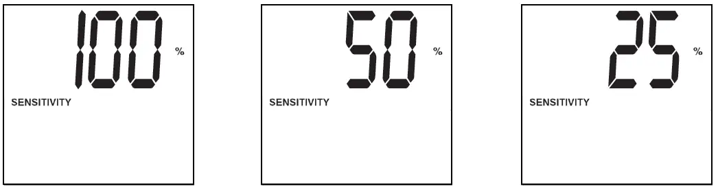
Sensitivity Icon: Displayed to set the AC input line sensitivity setting. Sensitivity settings available are 100% (high sensitivity), 50% (medium sensitivity), and 25% (low sensitivity).
SCROLL Icon: When enabled, the display will automatically cycle through each DISPLAY mode of the LCD once per two-second interval. If a button is pressed while Scroll Mode is enabled, the scroll function will pause for 10 seconds to allow the user to manually make menu selections before resuming scroll.
Automatic Voltage Regulation Icon: Indicates that the AC input is either low or high and that the AVR function is actively boosting or cutting the line. The AVR icon is also used in conjunction with the EVENTS icon to indicate AVR events.
BATTERY CAPACITY Icon: Used to better describe the battery capacity bar graph.
Display Power Conditions
Use the button to advance through power conditions.
Load Wattage is displayed in watts up to “999”, and then will be displayed in Kilowatts.
The Kilowatt Hour usage per day reports daily power consumption of equipment connected to the UPS in KWH in a 24-hour cycle. Press and hold the button for 4 seconds to reset the accumulator to “0”.
Note: When the UPS is in Battery Mode (power is supplied to the output from the batteries), the BATTERY icon will be lit in the display instead of the AC INPUT icon.
Control Menu Options
Enable/Disable Alarm
Tap the button repeatedly to advance to the LCD display featuring the icon. Press the button to select ON or OFF alarm mode settings. The last option displayed before navigating away from this menu option will be the selected setting.
Note: Disabling the alarm via this control menu option will silence the alarm under all conditions, including low battery conditions.
LCD Brightness
Tap the button repeatedly to advance to the LCD Brightness display marked “LCD”. Press the button to select Medium Backlight (default), High Backlight or Dim Backlight. The last option displayed before navigating away from this menu option will be the selected setting.
Note: The default brightness is set at medium. Any time a button is pressed, the LCD will engage the high brightness setting. After 2 minutes of inactivity, the backlight will revert to the selected setting until a button is pressed.
Self-test
Tap the button repeatedly to advance to the TEST BATT display. Press the button to initiate the test. The test will last approximately 10 seconds as the UPS switches to battery to test the capacity with a load. Upon completion of the test, the display will indicate PAS or BAD (pass or bad) for 20 seconds and then return to the home screen. Connected equipment can remain on during the test. Do not unplug your UPS to test it; this will remove safe electrical grounding.
A Replace Battery Condition will result in the Replace Battery and Warning icons flashing every second and the audible alarm sounding repeatedly.
Scroll Control
This display option allows the user to select the option to automatically scroll each operating condition of the UPS (such as Input Voltage, Output Voltage and Runtime).
Tap the button repeatedly to advance to the Scroll display as shown above.
Press the button to advance to the next available option. The last option displayed before navigating away from this menu option will be the selected setting.
Note:
- Each condition is displayed in 2 second intervals.
- If a button is pressed while Scroll Mode is enabled, the scroll function will pause for 10 seconds to allow the user to manually make menu selections.
ON Battery Events
This feature allows the user to view the number of times the UPS has experienced an ON Battery Event. To reset the counter to “0”, press and hold the button.

Tap the button repeatedly to advance to the ON Battery Events display, as shown above.
Note: The value displayed is a random value used for example reference.
AVR Events
This feature allows the user to view the number of times the UPS has experienced an Automatic Voltage Regulation Event. To reset the counter to “0”, press and hold the button.
Tap the button repeatedly to advance to the AVR display, as shown above.
Note: The value displayed is a random value used for example reference.
Power Sensitivity
This setting is normally set to 100%, which enables the UPS to protect against waveform distortions in its AC input. When such distortion occurs, the UPS will normally switch to providing pure sine wave power from its battery reserves for as long as the distortion is present. In some areas with poor utility power or where the UPS input power comes from a backup generator, frequent brownouts and/or chronic waveform distortion could cause the UPS to switch to battery too often, draining its battery reserves. Reduce how often your UPS switches to battery due to waveform distortion or brownouts by experimenting with different settings. As the setting is reduced, the UPS becomes more tolerant of variations in its input power’s AC waveform.
Note: When experimenting with different settings, operate connected equipment in a safe test mode so that the effect on the equipment of any waveform distortions in the UPS output may be evaluated without disrupting critical operations. The experiment should last long enough to assure that all expected line conditions are encountered.
Tap the button repeatedly to advance to Sensitivity display, as shown on the previous page.
Press the button to advance through the options. The last option displayed before navigating away from this menu option will be the selected setting.
Factory Mode Reset
The LCD settings can be restored to Factory Mode by holding the MODE and ENTER/MUTE buttons simultaneously for 5 seconds while in any display mode.
CAUTION: This action cannot be undone.
Other UPS Features (Rear Panel)
AC Outlets: The UPS includes NEMA 5-15R and NEMA 5-20R outlets. These outlets provide the connected equipment with AC line power during normal operation and battery power during blackouts and brownouts. The UPS protects equipment connected to these outlets against damaging surges and line noise. If there is an active serial or USB connection to the UPS, it is possible to remote reboot connected equipment by turning the outlets OFF and ON using Tripp Lite’s PowerAlert Software. The outlets are divided into one or more load banks (labelled “LOAD 1,” etc.) which may be remotely switched OFF and ON without interrupting power to equipment connected to the other outlets. Outlets labeled “UNSWITCHED” may not be remotely switched off.
Communications Ports (USB or RS-232): These ports connect the UPS to any workstation or server. Use with Tripp Lite’s PowerAlert Software and included cables to automatically save open files and shut down equipment during a blackout. Also use Power Alert Software to monitor a wide variety of AC line power and UPS operating conditions. Consult the PowerAlert Software manual or contact Tripp Lite Customer Support for more information. See USB and RS-232 Serial Communications in the Optional Installation section for installation instructions.
EPO (Emergency Power Off) Port: The UPS features an EPO port that may be used to connect the UPS to a contact closure switch to enable emergency inverter shutdown. See Optional Installation section for installation instructions
Accessory Slot: Remove the small cover panel from this slot to install optional accessories to remotely monitor and control the UPS. Refer to the accessory’s manual for installation instructions. Contact Tripp Lite Customer Support at
www.tripplite.com/support for more information, including a list of available SNMP, network management and connectivity products.
Ground Screw: Use this to connect any equipment that requires a chassis ground.
Troubleshooting
|
Fault/Error |
Fault/Error Code on the LCD |
Troubleshooting |
UPS Mode Transition |
Additional Comments |
| Communication lost with the Battery Management System (BMS). | E13 | Battery communication error. If E13 is observed, check wire connections between the UPS and the battery. If the problem persists, contact Tripp Lite for assistance. | When the UPS is in Line Power Mode, it will transfer to Pass Through Mode and continue to support the attached load(s) as long as AC is present.
Note: The incoming AC is not filtered or corrected by the UPS. If the UPS is in Battery Mode, output to the attached load(s) will be lost. |
The error code will remain showing on the LCD and cannot be cleared by the operator. Once communication
is re-established, code ‘F2’ will display on the LCD while the UPS re-establishes communication with the battery. Once battery communication is re-established, the code will no longer appear. |
| Critical Battery Protection Fault | F1 | A critical battery fault has been detected by the BMS. There is
a component malfunction. Turn off the UPS and contact Tripp Lite for assistance. This condition should only be examined by Tripp Lite technicians. |
When the UPS is in Line Power Mode, it will transfer to Pass Through Mode and continue to support the attached load(s) as long as AC is present.
Note: The incoming AC is not filtered or corrected by the UPS. If the UPS is in Battery Mode, output to the attached load(s) will be lost and the UPS will shut down. Similarly, if the incoming AC supply is lost, the UPS will not transfer to battery and the UPS will shut down. |
None. |
|
Fault/Error |
Fault/Error Code on the LCD |
Troubleshooting |
UPS Mode Transition |
Additional Comments |
| Non-Critical Battery Protection Faults | F2 | Non-Critical battery fault(s) detected by the BMS. Observe the steps shown
in the comments section. Once the fault has cleared, the error code will disappear and the UPS will display the normal operating screen. If the problem persists, contact Tripp Lite for assistance. |
When the UPS is in Line Power Mode, it will continue
to support the attached load(s) as long as AC is present. The incoming AC supply will be conditioned by the UPS. If the UPS is in Battery Mode, output to the attached load(s) will be lost. |
Non-critical faults are typically observed when the battery is subjected to extreme environmental conditions such as over current and/or over temperature. Reduce the load and let the UPS return to room temperature.
Recharge the battery for 24 hours and restart the UPS if necessary. |
| Charger Fault | F3 | Critical battery charging fault. The charge current has exceeded tolerance for more than 10 seconds or the battery voltage
has not reached sufficient capacity to start up the UPS. Ensure the battery has been charged for 24 hours. Restart the UPS or reset the fault by pressing “Enter/Mute” to revert to normal operation. If the problem persists, contact Tripp Lite for assistance. |
None. | If the battery has become severely depleted prior to startup, the UPS will enter the Aux. Charging Mode to trickle charge the battery up to an acceptable level before applying normal charging current. During this time, the user will be unable to turn on the output, and the battery icon will flash.
Once adequately charged, the unit will power up to normal Standby or Line Power Mode depending on autostart configurations. |
Fan Replacement
The cooling fan installed in the UPS should be replaced by qualified service personnel. Before proceeding with fan replacement, first put the UPS in OFF mode, disconnect the UPS from the AC mains, and disconnect any connected equipment. Use tools with insulated handles.
Remove Front Panel.
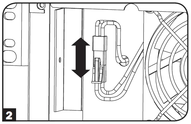
Disconnect the fan wires.
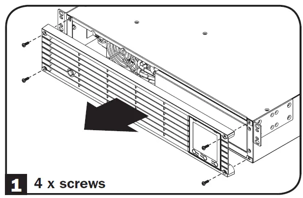
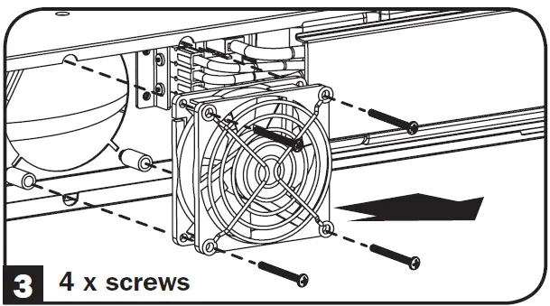
Remove the 4 Fan Screws.
Install the new fan by aligning the screw holes between the fan and the UPS. IMPORTANT: To ensure optimal airflow, the arrow on the side of the fan housing must point inward. Reinstall the fan screws.
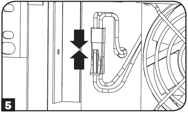
Reconnect the fan wires.

Replace Front Panel.
Storage and Service
Storage
Before storing the UPS, turn it completely OFF: with the UPS ON and receiving utility power, press and hold the “ON/OFF” button for two seconds (an alarm will beep once briefly after the interval has passed); then, unplug the UPS from the wall outlet. If storing the UPS for an extended period of time, recharge the UPS batteries once every three months: plug the UPS into a wall outlet; allow it to charge for 12 hours; and then unplug it and place it back in storage. If UPS batteries are discharged for an extended period of time, they will suffer a permanent loss of capacity.
Service
A variety of On-Site Service Programs are also available from Tripp Lite. For more information on service, visit www.tripplite.com/support. Before returning your product for service, follow these steps:
- Review the installation and operation procedures in this manual to insure that the service problem does not originate from a misreading of the instructions.
- If the problem continues, do not contact or return the product to the dealer. Instead, visit www.tripplite.com/support.
- If the problem requires service, visit www.tripplite.com/support and click the Product Returns link. From here you can request a Returned Material Authorization (RMA) number, which is required for service. This simple on-line form will ask for your unit’s model and serial numbers, along with other general purchaser information. The RMA number, along with shipping instructions will be emailed to you. Any damages (direct, indirect, special or consequential) to the product incurred during shipment to Tripp Lite or an authorized Tripp Lite service center is not covered under warranty. Products shipped to Tripp Lite or an authorized Tripp Lite service center must have transportation charges prepaid. Mark the RMA number on the outside of the package. If the product is within its warranty period, enclose a copy of your sales receipt. Return the product for service using an insured carrier to the address given to you when you request the RMA.
Product Registration
Visit www.tripplite.com/warranty today to register your new Tripp Lite product. You’ll be automatically entered into a drawing for a chance to win a FREE Tripp Lite product!*
No purchase necessary. Void where prohibited. Some restrictions apply. See website for details.
FCC Notice, Class A
This device complies with part 15 of the FCC Rules. Operation is subject to the following two conditions: (1) This device may not cause harmful interference, and (2) this device must accept any interference received, including interference that may cause undesired operation.
Note: This equipment has been tested and found to comply with the limits for a Class A digital device, pursuant to part 15 of the FCC Rules. These limits are designed to provide reasonable protection against harmful interference when the equipment is operated in a commercial environment. This equipment generates, uses, and can radiate radio frequency energy and, if not installed and used in accordance with the instruction manual, may cause harmful interference to radio communications. Operation of this equipment in a residential area is likely to cause harmful interference in which case the user will be required to correct the interference at his own expense. The user must use shielded cables and connectors with this equipment. Any changes or modifications to this equipment not expressly approved by Tripp Lite could void the user’s authority to operate this equipment.
Regulatory Compliance Identification Numbers
For the purpose of regulatory compliance certifications and identification, your Tripp Lite product has been assigned a unique series number. The series number can be found on the product nameplate label, along with all required approval markings and information. When requesting compliance information for this product, always refer to the series number. The series number should not be confused with the marketing name or model number of the product.
Tripp Lite has a policy of continuous improvement. Product specifications are subject to change without notice.
![]()