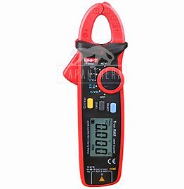
UNI-T UT210D Mini Clamp Meters Operation Manual
Mini Clamp Meters Operation Manual
I. Overview
UT21 OD mini digital clamp meter features high reliability, high safety, high accuracy and mini size. The circuit design of the complete machine takes the large scale integrated
circuit B/:J. analog-digital converter as core, and supported with full-range over-load protection circuit. It is applicable to measure DC voltage, AC voltage, frequency, resistance,
capacitance, diode, circuit on-off, temperature as well as non-contact AC/DC current and non-contact AC voltage electromagnetic field. Voltage & current true virtual value
response, full-range over-load protection, reliable measurement accuracy and unique appearance design make UT21 OD a new generation of practical electrotechnical/ electric measuring instrument with more excellent performance.
II. OOBA (Out-of-Box Audit)
Open the packing box and take out the instrument. Please
carefully check whether or not the following accessories
are missing or damaged. If you find any missing or damage,
please contact the supplier immediately.
1. Instructions ………………………….. one copy
2. AAA battery 1.5V. …………………… two pieces
3. Probe ………………………………….. one pair
4. Temperature probe …………………. one pair
Ill. Safety Instructions
The instrument is designed in conformity with CE certification, EN 61010-1, 61010-2-032 and 61010-2-033 of EU (pollution level 2), measurement category CAT II 600V
and CAT Ill 300V as well as double insulation safety standard. Before using, please read the operation instruction and follow all safety instructions:
Conforms to UL STD. 61010-1, 61010-2-032, 61010-2-033 Certified to CSA STD. C22.2 NO. 61010-1, IEC STD 61010-2-032, 61010-2-033 CAT II: Applicable to test and measuring circuits connected direcliy to utilization points (socket outlets and similar points) of the low-voltage MAINS installation. CAT Ill: Applicable to test and measuring circuits oonnected to the distribution part of the building’s low-voltage MAINS installation, before use and follow all safety instructions.
- Please follow the operation instruction to use clamp meter, otherwise, the protection provided by the instrument is likely to be weaken.
- Abide by the national laws and regulations; personal protective equipment must be applied to prevent from the injury caused by electric shock, arc discharge and so on, when working in the environment with bare live wire.
- Please do not reach beyond any position outside the protective shield of the current clamp meter.
- Before each use, check whether there are cracks or damages on the shell of current clamp meter and the output cable and whether there is any part under poor connection, and pay attention to the insulation layer surrounding the clamp mouth.
- Before removing the battery cover, please make sure to remove the clamp meter from all live circuits, and disconnect the leading wire.
- lt is prohibited to use this clamp meter on circuit with voltage of higher than 600V (CATll600V), or frequency of above 400Hz
- ?.Measurement category classification standard CAT II 600V CAT Ill 300V and pollution level 2 must not be violated.
- Be sufficiently careful when working in the environment with bare wires, for contacting with wires might lead to electric shock.
- Special attention shall be paid to 60V DC (direct current), 30V AC (alternating current effective value) or 42V AC (peak value), because there is risk of electric shock.
- If probe needs to be replaced, ones with the same CAT II 600V CAT Ill 300V level according to IEC 61010-031 shall be adopted.
- Before measuring, function switch must be placed at the correct position and tap positions are not permitted to be switched during measurement, so as to prevent the instrument
from damage. - Before it is used in high voltage circumstance, it is necessary to measure the known voltage, such as socket for civil use, to confirm validity of the instrument and prevent misleading
of damaged instrument.
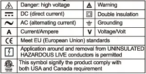
IV.. El ectnca ISiv m bOlS
V. Comprehensive Code
- Maximum misoperation protection voltage between the input terminal and grounding is 600V.
- .Maximum over-load protection current of the clamp head terminal is 200A.
- Maximum indication: 2,000 Counts, 2-3 times of updating per second. Over-range indicates “OL”.Diode: around 3.2V Measuring range: automatic Polarity: automatic
Working temperature: 0’C – 40′( Relative humidity: 0’C -30′(: ,;; 75%, 30′( – 40′(: ,;; 50% Storage temperature: -10′( – 50′( - .Electromagnetic compatibility: In radio-frequency field of 1V/m: total accuracy=dedicated accuracy+5%; as for radio-frequency field over 1V/m, there is no dedicated index.
- Working altitude: 0-2,000m
- Built-in battery: AAA 1.5Vx2 pieces
- Low battery: LCD displays” a “symbol.
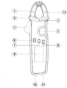
VI. Drawing for Product Panel (Figure 1)
- Clamp head.
- Protective shield.
- Clamp head trigger: press the trigger to open the clamp head.
- NCV indicator light: if induced AC electric field intensity and induced distance meet the indicated values, alarm will be given out and indicator light will flash.
- Function selection knob switch: turning this knob switch to switch to relevant functions on the panel.
- HOLD/ key: used to lock the measured readings; hold the key for 2 seconds to turn on or off the backlight.
- ZERO key: used for DCA reset and measurement of voltage /current/resistance/capacitance relative value.
- SELECT key: used for function selection at compound tap positions, such as ACV/Hz/DCV, resistance/circuit on-off/ diode/capacitance, ‘C/’F, etc.
- .LCD display screen: displaying interface of measurement function, symbol, value and so on. 1 a.Positive end jack: when testing voltage and resistance/ circuit on-off/capacitance/diode and measuring temperature with probe, insert red probe/temperature probe into this jack.
- COM end jack: when testing voltage, and resistance/circuit on-off/capacitance/diode and measuring temperature with probe, insert black probe/temperature probe into this jack.
- .Clamp head geometric center indication mark.
VII. Description of Symbols (Figure 2)

VIII. Operation Instructions
- Measuring of AC Voltage/Frequency/DC Voltage
• Select AC voltage/frequency or DC voltage tap position.
• Insert red probe into red jack (positive end), and insert
black probe into blackjack (COM end).
• Touch the measured part with red and black probes,
such as power socket (Figure II).
• Read the measured value from LCD screen.
 When measuring voltage or frequency, the maximum input voltage is 600V (AC/DC), and this is not allowed to be exceeded; otherwise, it is possible to cause
electric shock and damage the instrument.

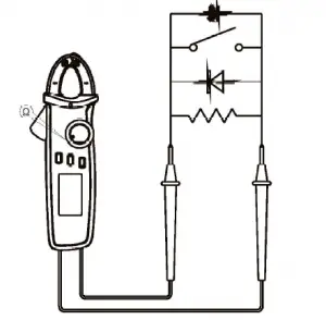
- Measuring of Resistance/Circuit on-off/ Diode /Capacitance
• Select corresponding functions.
• Insert red probe into red jack (positive end), and insert black probe into black jack (COM end).
• Connect the probe in parallel to the measured part (Figure 3).
• Read the measured value from LCD screen. Do not input voltage of higher than DC 60V or AC 30V ,
when measuring the range of resistance/capacitance/ diode, in order to avoid personal injury or damage of instrument.
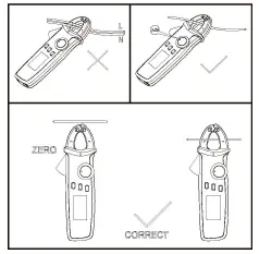
- 3. Measuring of AC/DC Current (Figure 4)
1) AC current
• Select geometric center position of AC current tap position; make sure the left and right clamp heads are completely closed, with no gap between them.
Read the measured data from LCD.
2) DC current
• Select DC current tap position.
• Press the ZERO reset key before measuring to clear the readings to zero.
• Open the clamp head, clasp the wire (single wire), and put the wire in the geometric center indicated in the clamp head. Make sure that the left and right clamp
heads are completely closed, without gap between them.
• Read the measured data from LCD. If the reading is positive, it means current flows from positive end marked on the clamp head to the negative end, and vice versa.
Take out the probe when measuring current, in order to avoid electric shock.
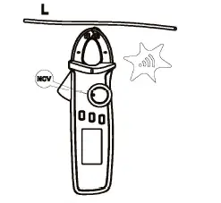
- 4. Measuring of NCV Non-contact Electric Field (Figure 5) The front end of clamp head can be used for sensing at 8-15mm from the tested object, in order to detect the
existence of AC voltage or electromagnetic field. When the simulating value of AC voltage: <,;threshold voltage of 1 OOV, it displays “EF”; > threshold voltage of 1 OOV, LCD will display”-“, i.e.,”-“,”–,”—” and”—” corresponding to the sensing voltage. Meanwhile, the buzzer will ring with differentiated rhythms and NCV light will flash, to
distinguish the intensity of the electric field. When measuring range is switched to NCV measuring, the measuring probe shall be pulled out to avoid electric shock.
- Measuring of Temperature
• Temperature sensor. only applicable to K type temperature sensor.
• Switch to select temperature tap position.
• Input end open circuit instrument displays OL, and displays ambient temperature in case of short circuit.
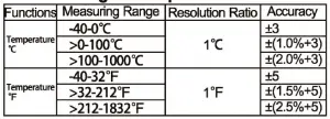
• Connect to K type temperature sensor with black probe into COM end and red probe into °C end to measure 0 ( or °F values. °F=1.8°C +32 Caution:
K type (nickel-chromium to nickel-silicon) point thermocouple temperature sensor configured is only applicable to measurement of temperature below 230°C/446°F. Measuring of higher temperature shall be performed with K type temperature sensor with applicable measuring range. - Other Functions
• Holding the HOLD key for 2 seconds to turn on or off LCD backlight. e Auto-OFF If the knob switch is not operated for 15 minutes during the process of measuring, the instrument will start “Auto-OFF” to save energy. During auto-OFF status, click any key to wake up the instrument, or turn the knob switch to OFF and restart it again. Auto-OFF means that the instrument enters super-low power consumption status.
• Stop auto-OFF: Hold SELECT key, and then connect and start the instrument, 5 times of buzzing will be given out to prompt that the autoOFF function will be cancelled. The auto-OFF function will be resumed when the instrument is switched off and then restarted.
• The buzzer will give out 5 times of alarm around 1 minute before starting auto-OFF status, and give out 1 long alarm before power-off. When auto-OFF function is cancelled, the
buzzer will give out 5 times of alarm every 15 minutes.
• Buzzer: buzzer will give out a short “beep” (about 0.25 second) if pressing any key or switching to valid functions. In tap positions, if the tested circuit is in sound conductivity
(<,;100), the buzzer will keep ringing. When the measured AC/DC voltage is higher than 600V or current is higher than
200A, the buzzer will also give out continuously interrupted “Beep” sound to warn against over-range.
• Low voltage detection: when the voltage is lower than 2.5V, low battery symbol “a” will be displayed, when measuring accuracy might be reduced, and new battery shall be used
in time. If the voltage is lower than 2.2V, the instrument will only show low battery symbol after starting, but will not work.
• When battery supply voltage is reduced to 2.6V, LCD backlight will be dim or cannot be started, but measuring function can still be available.
IX. Technical Indexes
Accuracy: ±(a% reading+b word count), warranty period is 1 year Ambient temperature: 23°(±5°( (73.4 °F±9°F), relative humidity: ~75%
- Measuring of DC Voltage
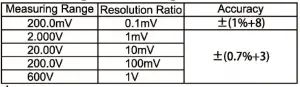
Voltage input impedance: about 1 OMO. (Due to the high input impedance, instable digit might be displayed in open circuit with 200mV measuring range, but such digit will be
able to be measured stably in case of connection to tested source with internal resistance of lower than 1 O MO; however, the influence of measured source on measuring reading
shall be considered.)
Maximum voltage input: ±600V - Measuring of AC Voltage
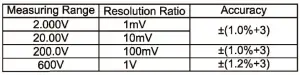
Voltage input impedance is all around 1 OMO.
Maximum voltage input: 600Vrms.
• Display true virtual value. Frequency response: 45-400Hz
• Accuracy assurance range: 5-100% measuring range, with less than 10 residual counts allowable in case of short circuit.
• The following deviation shall be added to calculate non -sinusoidal wave based on crest factor:
a)Crest factor is 1-2: add 3%.
b)Crest factor is 2-2.5: add 5%.
c)Crest factor is 2.5-3: add 7%. - Measuring of Frequency

- Measuring of Resistance
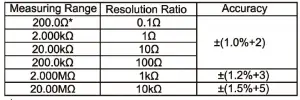
* Measuring range: measured value=displayed value-probe short circuit value Open circuit voltage: around 1V Overload protection: 600V-PTC - ••ll Circuit on-off and * Measuring of Diode

A Overload protection: 600V-PTC - Measuring of Capacitance

Overload protection: 600V-PTC
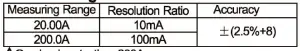
• For tested capacitance of ~ 1 μF, it is suggested to test under ZERO mode to ensure measuring accuracy. - Measuring of DC Current
Overload protection: 200A
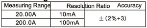
• Due to existence of the earth and other magnetic fields, and in order to ensure the accuracy of measuring readings, ZERO key shall be pressed before measuring. - Measurin of AC current
Overload protection: 200A
• Accuracy assurance range: 5-100% measuring range, with less than 20 residual counts allowable in case of 2A open circuit.
• Display true virtual value. Frequency response: 50-60Hz
• The following deviation shall be added to calculate nonsinusoidal wave according to crest factor.
a) Crest factor is 1-2: add 3%.
b) Crest factor is 2-2.5: add 5%.
c) Crest factor is 2.5-3: add 7%.
- Measuring of Temperature
X. Maintenance and Repair
warning: please be sure to cut off the power supply before opening the rear cover of the instrument, and pull out the probe from the jack and the tested circuit.
- General Maintenance
• The shell shall be regularly deaned by wet doth and deanser. Ab rad ant or solvent shall not be applied.
• If abnormities are found in the instrument, stop using and send it for repair.
• If validation or repair is needed, the instrument shall be sent to be repaired by qualified professional maintenance staff or designated maintenance department. - Battery Replacement (as shown in Figure 6) * If LCD displays low battery symbol “Gill”, the internal battery shall be replaced immediately, otherwise it
will influence the accuracy of measuring.
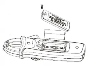
• Battery specification: AAA 1.5v x 2pieces Operation Sequence Figure 6 - Tum the power switch to “OFF” position, and remove the probe from the jack.
- Unscrew the screw in rear battery cover. Take out the batteries as per the figure.
- Replace 2PCS new batteries (specification: AAA 1.5V) Manufacturer: Uni-Trend Technology(China) Limited No 6. Gong Ye Bei 1st Road Songshan Lake National High-Tech Industrial
Development Zone, Dongguan City Guangdong Province China Postal Code:523 808
Headquarters:
Uni-Trend Group Limited Rm901, 9/F, Nanyang Plaza 57 Hung To Road KwunTong Kowloon, Hong Kong Tel: (852) 2950 9168
Fax: (852) 2950 9303
Email: [email protected]
http://www.uni-trend.com
