![]() ecoTEC pro
ecoTEC pro
VUW ..6/5-3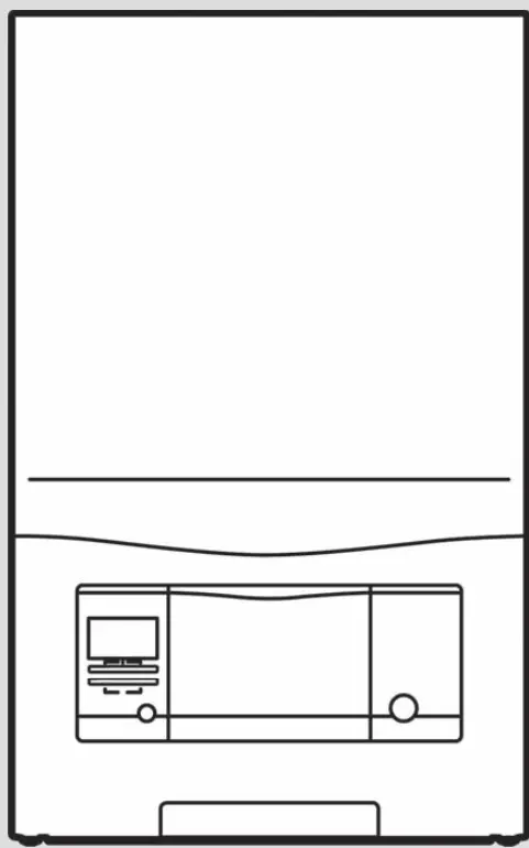 Operating instructions
Safety
Action-related warnings
Classification of action-related warnings The action-related warnings are classified in accordance with the severity of the possible danger using the following warning signs and signal words:
Warning symbols and signal words
![]() Danger!
Danger!
Imminent danger to life or risk of severe personal injury
![]() Danger!
Danger!
Risk of death from electric shock
![]() Warning.
Warning.
Risk of minor personal injury
![]() Caution.
Caution.
Risk of material or environmental damage
Intended use
There is a risk of injury or death to the user or others, or of damage to the product and other property in the event of improper use or use for which it is not intended. The product is intended as a heat generator for sealed heating installations and for domestic hot water generation. Intended use includes the following:
– observance of the operating instructions included for the product and any other installation components
– compliance with all inspection and maintenance conditions listed in the instructions.
This product can be used by children aged 8 years and above and persons with reduced physical, sensory or mental capabilities or lack of experience and knowledge if they have been given supervision or instruction concerning the use of the product in a safe way and understand the hazards involved. Children must not play with the product. Cleaning and user maintenance work must not be carried out by children unless they are supervised. Any other use that is not specified in these instructions, or use beyond that specified in this document, shall be considered improper use. Any direct commercial or industrial use is also deemed to be improper. Caution. Improper use of any kind is prohibited.
General safety information
1.3.1 Installation by competent persons only
The installation, inspection, maintenance, and repair of the product, as well as the gas ratio settings, must only be carried out by a competent person.
The danger caused by improper operation
Imaypresents a danger to you and others, and cause material damage.
- Carefully read the enclosed instructions and all other applicable documents, particularly the “Safety” section and the warnings.
- Only carry out the activities for which instructions are provided in these operating instructions.
Risk of death from escaping gas
What to do if you smell gas in the building:
- Avoid rooms that smell of gas.
- If possible, open doors and windows fully and ensure adequate ventilation.
- Do not use naked flames (e.g. lighters, matches).
- Do not smoke.
- Do not use any electrical switches, main plugs, doorbells, telephones or other communication systems in the building.
- If it is safe to do so, close the emergency control valve or the main isolator.
- If possible, close the gas stopcock on the product.
- Warn other occupants in the building by yelling or banging on doors or walls.
- Leave the building immediately and ensure that others do not enter the building.
- Notify the gas supply company or the Emergency Service Provider at +44 (0) 800 111999 by telephone once you are outside of the building.
Risk of death due to blocked or leaking flue pipework
What to do if you smell flue gas in the property:
- Open all accessible doors and windows fully to provide ventilation.
- Switch off the product.
- Inform a competent person. 1.3.5 Risk of death due to explosive and flammable materials
- Do not use the product in storage rooms that contain explosive or flammable substances (such as petrol, paper or paint).
Risk of death due to changes to the product or the product environment
- Never remove, bridge or block the safety devices.
- Do not tamper with any of the safety devices.
- Do not damage or remove any tamperproof seals on components.
- Do not make any changes:
– The product itself
– to the gas, supply air, water and electricity supply lines
– to the entire flue system
– to the entire condensate discharge system
– to the expansion relief valve
– to the drain pipework
– to constructional conditions that may affect the operational reliability of the product
Risk of corrosion damage due to unsuitable combustion and room air
Sprays, solvents, chlorinated cleaning agents, paint, adhesives, ammonia compounds, dust, or similar substances may lead to corrosion on the product and in the air/flue pipe.
- Ensure that the combustion air supply is always free of fluorine, chlorine, sulfur, dust, etc.
- Ensure that no chemical substances are stored at the installation site.
Risk of material damage caused by frost
- Ensure that the heating installation always remains in operation during freezing conditions and that all rooms are sufficiently heated.
- If you cannot ensure the operation, have a competent person drain the heating installation.
Risk of injury and material damage due to maintenance and repairs carried out incorrectly or not carried out at all
- Never attempt to carry out maintenance work or repairs on your product yourself.
- Faults and damage should be immediately rectified by a competent person.
- Adhere to the maintenance intervals specified.
Notes on the documentation
Observing other applicable documents
- You must observe all operating instructions enclosed with the system components.
.2.2 Storing documents
- Keep this manual and all other applicable documents safe for future use.
Applicability of the instructions These instructions apply only to:
Product article number
| Article number | Gas Council Number | |
| ecoTEC pro 30 H combi A VUW 306/5‑3 | 0010016538 | 47-044-52 |
Product description
Product design
Control elements
- On/off button
- The built-in controller (accessory)
- Fault clearance button
- Operating buttons
- Display
Operator control panel
- Current heating flow temperature, filling pressure of the heating installation, operating mode, fault code, or additional information
- Current assignment of the right-hand selection button
- Left- and right-hand selection buttons
- and button
- Maximum output operation (for chimney sweeps only)
- Access to the menu for additional information
- Current assignment of the left-hand selection button
- Active operating status
Displayed symbols
| Symbol | Meaning | Explanation |
 |
Burner operating cor- rectly | Burner on |
 |
The current filling pressure of the heating system The dashed lines show the permitted range | — Permanently on: Filling pressure in the permitted range — Flashing: Filling pressure outside the permitted range |
 |
Hot water generation active | — Permanently on: Draw-off mode be- fore burner is on — Flashing: Burner on in the draw-off mode |
 |
Heating mode active | — Permanently on: Heating mode heat requirement — Flashing: Burner on in the heating mode |
 |
Comfort mode active | — Permanently on: Comfort mode active — Flashing: Comfort mode active, burner on |
 |
Maintenance required | Information on the maintenance message in the “Live Monitor” |
 |
Summer mode active Heating mode is switched off | |
 |
Burner anti-cycling time is active | To avoid the need for frequent switching on and off (increases the product’s working life). |
 |
Fault in the product | Appears instead of the basic display, maybe an explanatory plain text display. |
Information on the identification plate
The identification plate is mounted on the underside of the product in the factory.
| Information on the identification plate | Meaning |
| Read the instructions. | |
| BUT… | Vaillant gas-fired wall-hung boiler for heating and hot water generation |
| ..6/5-3 | Calorific value power/product generation equipment |
| ecoTEC pro | Product description |
| 2H, G20 — 20 mbar (2.0 kPa) |
Gas group and gas connection pressure asset at the factory |
| WW/yyyy | Date of manufacture: Week/year |
| Cat. | Permissible gas categories |
| Types | Approved gas-fired units |
| PMS | Permissible total overpressure in heating mode |
| BMW | Permissible total overpressure during hot water generation |
| Tmax. | Max. flow temperature |
| ED 92/42 | Current efficiency directive fulfilled with 4* rating |
| V Hz | Mains voltage and mains frequency |
| W | Max. electrical power consumption |
| IP | Level of protection |
|
Heating mode |
|
Hot water generation |
| P | Nominal heat output range |
| Q | Heat input range |
| D | Nominal hot water draw-off rate |
 |
Bar code with serial number, 7th to 16th digit = product article number |
Serial number
The serial number is located on a plastic plate at the bottom of the front casing.
CE marking

The CE marking shows that the products comply with the basic requirements of the applicable directives as stated on the declaration of conformity.
The declaration of conformity can be viewed at the manufacturer’s site.
Energy Saving Trust Endorsed Products
Only the most energy-efficient products can carry the ‘Energy Saving Trust Endorsed Product’ brandmark making it easy for consumers to choose products that have met strict energy performance criteria.
Available for: Boilers, Heating controls, and chemical inhibitors, the Energy Saving Trust endorsed product brandmark gives consumers confidence that a product will cost less to run, help lower energy bills and reduce carbon emissions.
About the Energy Saving Trust,
Energy Saving Trust is an independent and impartial organization that provides trusted energy-saving advice to empower millions of people to lead affordable, low-energy lifestyles. For more information visit energysavingtrust.org.uk
Benchmark
Vaillant is a licensed member of the Benchmark Scheme which aims to improve the standards of installation and commissioning of domestic heating and hot water systems in the UK and to encourage regular servicing to optimize safety, efficiency and performance.
Benchmark is managed and promoted by the Heating and Hotwater Industry Council. For more information visit www.benchmark.org.uk.
- Please ensure that the installer has fully completed the Benchmark Checklist on the inside back pages of the installation instructions supplied with the product and that you have signed it to say that you have received a full and clear explanation of its operation. The installer is legally required to complete a commissioning checklist as a means of complying with the appropriate Building Regulations (England and Wales).
All installations must be notified to Local Area Building Control either directly or through a Competent Person Scheme. A Building Regulations Compliance Certificate will then be issued to the customer who should, on receipt, write the Notification Number on the Benchmark Checklist. This product should be serviced regularly to optimize its safety, efficiency and performance. The service engineer should complete the relevant Service Record on the Benchmark Checklist after each service. The Benchmark Checklist will be required in the event of any warranty.
Operation
Operating concept
| Control element | Function |
 |
– Setting the domestic hot water temperature – Cancelling the activation of an operating mode – Cancelling a change to a set value – Going one selection level higher |
|
– Setting the heating flow temperature – Reading the system pressure – Activating the comfort mode – Activating the operating mode – Confirm the set value – Going one selection level lower |
| ++ at the same time |
– Calling up the menu |
| – or+ | – Reducing or increasing the set value – Scrolling through menu entries |
The current function of the and buttons is shown in the display.
Adjustable values are always displayed as flashing.
You must always confirm a change to a value. Only then is the new setting saved. You can press to cancel a proced- ure.
Basic display
The basic display shows the current condition of the product. If you press a selection button, the activated function is displayed in the display. The functions that are available depend on whether a control is connected to the product. You can switch back to the basic display by:
– Pressing to exit the selection levels
– Not pressing any button for longer than 15 minutes. If there is an error message present, the basic display switches to the error message.
Adjustment and display levels
The product has two adjustment and display levels. The end-user level contains information and setting options that you require as the end-user. The installer level is reserved for the competent person. It is protected by a code. Only competent persons may change any settings in the installer level.
Cupboard installation
Enclosing the product in cupboard installation requires compliance with the applicable design instructions. If you require cupboard installation for your product, consult a specialist company. Never, under any circumstances, enclose the product yourself.
Opening the isolator devices
- Ask the competent person who installed the product to explain to you where these isolator devices are located and how to handle them.
- Open the gas isolator cock fully.
- Open the service valves in the heating installation’s flow and return.
Condition: Product with integrated hot water generation or connected domestic hot water cylinder
- Open the cold water stop valve.
Starting up the product
- Only startup the product once the casing has been completely closed.
Switching on the product
- Press the on/off button (1).
- The “Basic display” (→ Page 7) (2) appears in the display.
Setting the heating flow temperature
1. Press( ).
- The target value of the heating flow temperature appears on the display.
Note
The competent person may have adjusted the maximum possible temperature.
Condition: No control connected
- Use or to set the required heating flow temperat- ure.
- Confirm by pressing.
Condition: Control connected
- Set the maximum possible heating flow temperature on the product.
- Confirm by pressing.
- Set the required heating flow temperature on the control (→ Control operating instructions).
Setting the hot water temperature
Danger! Risk of death from legionella. Legionella multiplies at temperatures below 60 °C.
- Have a competent person inform you about the measures that should be taken to protect against Legionella in your installation.
- Do not set any water temperatures below 60 °C without consulting the competent person first.
1. Press( ).
◁ The set hot water temperature flashes in the display.
Condition: No controller connected
- Change the hot water temperature by pressing
 or .
or . - Confirm by pressing .
Condition: Controller connected
- Use to set the maximum possible hot water temperature on the product.
- Confirm by pressing.
- Set the required hot water temperature on the controller (→ Controller operating instructions).
Switching the comfort mode on and off
Note
Comfort mode immediately supplies hot water at the required temperature, without you having to wait for the water to heat up.
- Press ( ).
- Press ( ). ◁ Conf. on or Conf. off are shown flashing in the display.
- Activate or deactivate comfort mode by pressing or .
- Press to confirm this change. ◁ When you have activated comfort mode, the ” ” symbol appears in the basic display. When you have deactivated comfort mode, the ” ” symbol goes out in the basic display.
Switching off the product’s functions
Switching off heating mode (Summer mod
- To switch off heating mode without switching off the domestic hot water generation, press ( ).
◁ The value of the heating flow temperature appears in the display. - Use the button to set the heating flow temperature to Off.
- Confirm by pressing.
◁ The heating mode is switched off.
◁ The symbol appears in the display.
Guaranteeing the correct filling pressure of the heating installation
Checking the filling pressure of the heating installation
Note To ensure that the heating installation operates smoothly, the filling pressure when the heating installation is cold must be between 0.10 MPa and 0.20 MPa (1.0 bar and 2.0 bar) or lie between the two dashed lines in the bar graph display.
If the heating installation extends over several stories, a higher filling pressure may be required for the heating installation. Ask a competent person for details.
In addition, the symbol appears after approx. one minute.
If the filling pressure in the heating installation falls below 0.05 MPa (0.5 bar), then the product switches off. The display alternates between the fault message F.22 and the current filling pressure.
- Press twice. ◁ The values for the current filling pressure and for the minimum and maximum filling pressures appear in the display.
- Check the filling pressure in the display. Result 1: System pressure: 0.10 to 0.20 MPa (1.00 to 2.00 bar) The filling pressure is in the intended pressure range. Result 2: Filling pressure: < 0.08 MPa (< 0.80 bar
- Fill the heating installation. (→ Page 9) ◁ If you have topped up the installation with sufficient heating water, the display automatically disappears after 20 seconds.
Filling the heating installation
![]() Caution. Risk of material damage due to heating water that is extremely calciferous or corrosive or contaminated by chemicals. Unsuitable tap water damages the seals and diaphragms blocks components in the product and heating installation through which the water flows and causes noise.
Caution. Risk of material damage due to heating water that is extremely calciferous or corrosive or contaminated by chemicals. Unsuitable tap water damages the seals and diaphragms blocks components in the product and heating installation through which the water flows and causes noise.
- Only fill the heating installation with suitable heating water.
- Ask a competent person where the filling cock is located.
- Connect the filling tap to a heating water supply in the way you were told by the competent person.
- Open all radiator valves (thermostatic radiator valves) of the heating installation.
- Open the heating water supply.
- Turn the filling cock on slowly and allow water to flow in until the required filling pressure has been reached.
- Close the heating water supply.
- Purge all radiators.
- Check the filling pressure in the display.
- Top up with more water if necessary.
- Close the filling cock.
- Return to the basic display. (→ Page 7)
Protecting the heating installation against frost
Frost protection function
![]() Caution. Risk of material damage due to frost. The frost protection function cannot guarantee flow through the entire heating installation, which means that parts of the heating installation may freeze and therefore become damaged.
Caution. Risk of material damage due to frost. The frost protection function cannot guarantee flow through the entire heating installation, which means that parts of the heating installation may freeze and therefore become damaged.
- During a period of frost, ensure that the heating installation remains in operation and that all rooms are sufficiently heated, even when you are away.
![]() Note
Note
To keep the frost protection devices active, you should switch your product on and off using the control, if one is installed.
If the heating flow temperature falls below 5 °C when the on/off button is on, the product starts up and heats the circulating water to approx. 30 °C on both the heating side and the domestic hot water side (if available).
Draining the heating installation
When the unit is switched off for an extended period, frost protection can be guaranteed by completely draining the heating installation and the product.
- Consult a competent person about this.
Troubleshooting
Detecting and rectifying faults
- If faults occur, proceed in accordance with the table in the appendix. Troubleshooting (→ Page 12)
- If the fault cannot be eliminated using the specified measures or if fault messages (F.xx) occur, contact a competent person.
Calling up (Live monitor) status codes
- Press and at the same time. Status codes – Overview (→ Page 12) ◁ The current operating mode (status code) is shown on the display.
Care and maintenance
Maintenance
An annual inspection of the product carried out by a competent person is a prerequisite for ensuring that the product is permanently ready and safe for operation, reliable, and has a long working life.
Caring for the product
- Clean the casing with a damp cloth and a little solvent-free soap.
- Do not use sprays, scouring agents, detergents, solvents or cleaning agents that contain chlorine.
Reading maintenance messages
If the symbol is shown in the display, the product requires maintenance work. The product is not in fault mode but continues to operate.
- Consult a competent person about this.
- If the water pressure is flashing at the same time, simply add more heating water.
Checking the condensate discharge pipe and tundish
The condensate discharge pipe and tundish must always be penetrable.
- Regularly check the condensate discharge pipe and tundish for faults and, particularly, for blockages. You must not be able to see or feel any obstructions in the condensate discharge pipe and tundish.
- If you notice a fault, have it eliminated by a competent person.
Decommissioning
Temporarily decommissioning the product
Caution. Risk of material damage due to frost. The frost protection and monitoring devices are only active while the product is connected to the power grid and switched on via the on/off button, and when the gas stopcock is open.
- Temporarily decommission the product only if no frost is expected.
- Temporarily decommission the product only if no frost is expected.
- Press the on/off button.
- The display goes out.
- When decommissioning the product for a prolonged period (e.g. holiday), close the gas isolator cock and also, for combination products, the cold water stop valve.
Permanently decommissioning the product
- Have a competent person permanently decommission the product.
Recycling and disposal
- The competent person who installed your product is responsible for the disposal of the packaging.
![]() If the product is labeled with this mark:
If the product is labeled with this mark:
- In this case, do not dispose of the product with the household waste.
- Instead, hand in the product to a collection center for waste electrical or electronic equipment.
![]() If the product contains batteries that are labeled with this mark, these batteries may contain substances that are hazardous to human health and the environment.
If the product contains batteries that are labeled with this mark, these batteries may contain substances that are hazardous to human health and the environment.
- In this case, dispose of the batteries at a collection point for batteries.
Guarantee and customer service
Guarantee
– One year guarantee for eco
TEC pro appliances Vaillant undertakes to rectify any manufacturing defect that occurs within twelve months of the installation date.
– Registering with us Registration is simple. Just complete the Guarantee Registration Card and return it to Vaillant within 30 days of installation. Your details will then be automatically registered within the Vaillant scheme.
![]() Note
Note
No receipt will be issued.
– Immediate help
If your Vaillant boiler develops a fault your first action should be to contact your installer, as his professional assessment is needed under the terms of our Guarantee. If you are unable to contact your installer, phone Vaillant Service Solutions: Telephone: 0330 100 3461
Customer service
To ensure regular servicing, it is strongly recommended that arrangements are made for a Maintenance Agreement.
Please contact Vaillant Service Solutions for further details: Telephone: 0330 100 3461
Appendix
A Status code – Overview
Status codes that are not listed here can be viewed in the installation instructions.
| Status code | Parameter | Meaning |
| Displays in heating mode | ||
| S.00 | Heating: No heat demand | Heating: No heat demand |
| S.02 | Heating mode: Pump pre-run | Heating mode: Pump pre-run |
| S.03 | Heating mode: Ignition | Heating mode: Ignition |
| S.04 | Heating mode: Burner on | Heating mode: Burner on |
| S.06 | Heating mode: Fan overrun | Heating mode: Fan overrun |
| S.07 | Heating mode: Pump overrun | Heating mode: Pump overrun |
| S.08 | Heating mode: Anti-cycling time | Heating, remaining anti-cycling time xx mins |
| Displays in hot water handling mode | ||
| S.10 | DHW demand | Hot water requirement via flow sensor |
| S.14 | DHW mode: Burner on | DHW mode: Burner on |
| Displays in Comfort mode with warm start or hot water handling mode with cylinder | ||
| S.20 | DHW demand | Hot water requirement |
| S.22 | DHW mode: Pump pre-run | DHW mode: Pump pre-run |
| S.24 | DHW mode: Burner on | DHW mode: Burner on |
| Others | ||
| S.31 | No heat demand: Summer mode | Summer mode active |
| S.34 | Heating mode: Frost protection | Frost protection mode, frost protection |
| S.46 | Waiting time: Measuring program | Comfort protection mode, flame loss at minimum load |
B Troubleshooting
| Fault | Cause | Measure |
| The product does not startup: – No hot water – Heating remains cold |
The gas isolator cock installed on-site and/or the gas isolator cock on the product is closed. | Open both gas isolator cocks. |
| The power supply in the building is disconnected. | Check the fuse in the building. The product switches on automatically when the power is restored. | |
| The product is switched off. | Switch on the product (- “Switching on the product” section). | |
| The heating flow temperature is set too low or to the Heating off position, and/or the hot water temperature is set too low. | Set the heating flow temperature and hot water temperature (- “Setting the heating flow temperature” section/-> “Setting the hot water temperature” section). | |
| The system pressure is insufficient. Low water pressure in the heating installation (fault message: F.22). |
Fill the heating installation (- “Filling the heating installation” section). | |
| There is air in the heating installation. | Have your competent person purge the heating installation. | |
| After three unsuccessful attempts to ignite the flame, the product switches to fault mode (fault message: F.28). | Press the fault clearance key for one second. The product makes another attempt to ignite the flame. If you have been unable to eliminate the ignition fault after three fault clearance attempts, consult a competent person. |
|
| Hot water generation functioning correctly; heating does not startup. | The external controller is not set correctly. | Set the external controller correctly (-> Controller operating instructions). |

Supplier
Vaillant Ltd.
Nottingham Road
DE56 1JT
Telephone 0330 100 3461
[email protected]
Belper
Derbyshire
www.vaillant.co.uk
Publisher/manufacturer
Vaillant GmbH
Berghaus Str. 40
D-42859 Remscheid
Tel. +492191 18 0
Fax +492191 18 2810
[email protected]
www.vaillant.de
© These instructions, or parts thereof, are protected by copyright and may be reproduced or distributed only with the manufacturer’s written consent.
Subject to technical modifications.