LAUREL MOUNTAIN – OWNER’S MANUAL
For your installation, operation, and maintenance needs for all Colony units.
Specifications
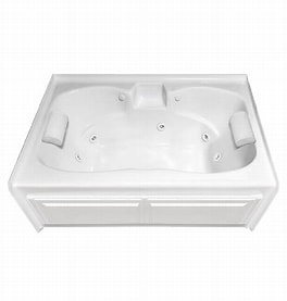
Your Laurel Mountain Whirlpools unit was created to your order specifications. The tub was constructed from a cast acrylic shell. It was then reinforced with a mixture of chopped fiberglass in a polyester resin applied to the backside of the shell. The base of your unit was designed to give uniform support to the tub floor and has been pre-leveled. It meets or exceeds load-bearing and impact resistance requirements of the listed standard without evidence of crazing or cracking and with minimal deflection when installed in accordance to Laurel Mountain Whirlpools printed instructions.
PRIOR TO INSTALLATION
Immediately inspect your tub upon arrival. If any damage has occurred, make a notation on the freight carrier’s proof of delivery. DO NOT remove the bath from its shipping container until you are ready to watertest and install. When you are prepared to remove the tub from its carton DO NOT LIFT the tub out by its plumbing. We also recommend cutting cardboard from the shipping container to place inside the tub to protect its floor. Even though your tub has been inspected and water tested prior to shipment, it is very important that you perform a water test of your own to ensure all of the fittings and connections were not damaged during transit. Take your tub to an area where you can fill it up, run electrical components, & drain it. Fill your tub to the overflow and if you have a pump and/or blower, operate it for 15 minutes. Inspect the entire unit during and after for leaks. Any defects that are discovered MUST be reported at this time to qualify for warranty coverage. Qualified plumbers and electricians MUST be used for all tub connections to assure you follow local codes and acquire any permits required for the install. NEVER LIFT the unit by any portion of the plumbing or stand in the unit during installation as this may cause serious damage to the unit.
Framing-in Your Bath
*It is VERY important that your tub is supported by its base and not the rim.
*Take your installation measurements directly from your tub, as they may vary slightly from our literature. When installing the drain fitting, you will notice it protrudes below the bottom of the tub. You will need to allow clearance in the sub-floor for this dimension. Now you are ready to place your tub in its desired location. Check the unit and sub-floor to ensure it is level. If it is not, insert wood shims between the sub-floor and support base. Mark stud wall underneath the tub’s return lip. Remove the unit from position and install a 1x stop to stud wall for lip to rest on to prevent deflection. At this time, check to see if any wiring needs to be completed (see wiring instructions). Since a great variety of installations are possible with this bath, special framing procedures may be needed. A ledge under the rim, or an apron without a ledge, may be constructed as required. Where installation is planned against a wall, install the tub against the studs as indicated, adding blocking below the rim to prevent deflection or movement of the tub, but ensuring that the weight of the tub is not supported in any way by the blocking (Diagram A). When placing the unit in a platform floor or cut out installation, the opening should be 1” smaller than the specified rim dimensions.
If your model has an integral tile flange, the unit should be placed in a pre-measured studded pocket. Pre-drill holes through the flange to align with studs. Use screws to secure studs (Diagram B). DO NOT attempt to nail directly through the flange. Always pre-drill the holes. In every “system” installation, an access panel must be placed near the pump/blower for servicing. This access may be through the wall or platform apron. In the case of a sunken installation, access may be through the ceiling below the bathtub. See Diagram C for instructions for the access panel provided on the skirted tub.
Diagram C – To remove skirt panel, simply pry loose at the top corners and pull outward (away from the frame). To reinstall skirt panel, simply set panel in frame (bottom side first) and push or ward. Lightly depress he tabs on the top of the panel while pushing forward until the panel snaps into its frame.

Electrical and Wiring Instructins
Rough in the wiring on a single 120VAC, 20 amp, GFCI protected dedicated circuit for each whirlpool, air system, or heater installed on the tub.
WARNINGS:
- All electrical connections must be made by a licensed certified electrician in accordance with the requirements of the National Electrical Code and applicable state and local codes and procedures.
- All circuits connected to this unit must be equipped with Ground Fault Circuit Interrupter (GFCI) protection. It is the tub installer’s responsibility to wire the circuit with GFCI.
- All bathtubs equipped with an inline heater require two dedicated circuits. One for the whirlpool system and one for optional inline heater.
- DO NOT splice a longer cord to the power supply cord and DO NOT connect to an extension cord.
All whirlpool, air systems, and heaters are equipped with a molded plug on the end of a power supply core. One or two outlet boxes will be factory installed to accommodate up to three plugs. Electric power must be supplied to the outlet boxes. Install a separate, dedicated 120VAC, 20 Amp GFCI protected electrical wall plug outlet inside the access panel for each pump, blower, and heater equipped on the tub. For example, if the tub is equipped with a whirlpool system only, then one GFCI wall plug outlet is necessary. If the tub is equipped with both whirlpool system and a heater then two separate circuits with GFCI wall plug outlets are required. Be sure to count the number of accessories before installing the GFCI wall outlets. Also, the power supply cords equipped with each accessory are only 2.5’ long so locate the GFCI wall outlet within 1.5’ of the intended accessory.
Electrical Requirements
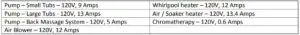
Please note, that when sizing the electrical circuits to power the unit, you should always check the rating labels on equipment because there could be changes.
Plumbing Installation
Install fill valves and spout in the desired locations. Note, due to various possible fill valve and spout locations, the holes are not drilled at the factory. Make certain that the spout is long enough to clear the interior rim of the tub. If installing fill valves on the deck of the tub, be sure that you have enough clearance for connections
of valve to tub and water connections before drilling/cutting into tub. Seal the joints under the tub rim and against the wall with a water resistant seal. Then install a standard 1.5” trap to the drain and overflow.
Before proceeding, make a final operational check by filling the tub with water to the overflow and operate for at least 5 minutes. Leave the water in the bath for 30 minutes, check the connections for leaks during and after operation. Complete the installation with desired trim material on the back wall, side walls, and down exposed interior walls.
Operation Instructions
Laurel Mountain Whirlpools will not be held responsible for water damage of any kind in connection with the installation and/or operation of one of our bathtubs. All whirlpool jets must be completely submerged below water before starting the pump. Do not operate the pump without water as damage may occur. Do not block the overflow drain and allow water to reach the controls as they are not waterproof and leaks to the floor may occur.
Important Safety Instructions
Do
Ensure your qualified electrician supplies a Ground Fault Circuit Interrupter (GFCI) during installation. This offers necessary protection to your unit and should be tested periodically. To test, simply push the and power should be interrupted. Then push the and power should be restored. If not, DO NOT use the unit as this indicated there is a ground current flowing and that a possibility of ELECTRIC SHOCK exists. Disconnect the unit at once and call a qualified electrician before further operation.
Use this tub for its intended purposes described in this manual. The manufacturer does not recommend using any attachements not specifically approved in this manual.
Do Not
- Allow any electrical appliances near the bathtub.
- Use alcohol, drugs or medication. This will greatly increase your risk of hypothermia or drowning.
- Use this tub if you think or know you are pregnant. Consult your physician first.
- Allow children to use the bathtub without adult supervision.
- Operate the whirlpool without the suction cover.
- Insert any objects into any of the openings.
- Use options NOT installed by the manufacturer.
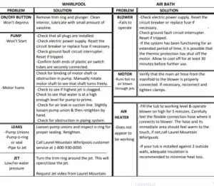
Care and Cleaning Instuctions
WHIRLPOOL
Prior to using the whirlpool, the tub and its system(s) should be thoroughly cleaned and disinfected. DO NOT use abrasive cleaners on the high-gloss acrylic finish. Use a non-abrasive cleaner and rinse thoroughly after cleaning. To remove the labels on the tub, we recommend using fingernail polish remover if they do not come
off easily. Fill the tub up with water at least 2” above the highest jet, then add 2 tsp. of low sudsing automatic dish washing detergent and no more than 8 oz. of household bleach. Operate your whirlpool for 5-10 minutes and then drain the tub. Refill the tub with water and run the system for another 5 minutes, then drain. Repeat every 30 days unless an ozonator was purchased.
ALL TUBS
Your bath has an acrylic finish and will retain its high luster for years with proper care. Never use an abrasive cleaner or pad to clean your bath tub. Always use a soft cloth or sponge along with a spray liquid non-abrasive bath cleaner/disinfectant. On the metallic finish, use only a soft cloth and warm soapy water.
Whirlpool Operation
If your bath has a whirlpool system, simply pushing the push-button located on the tub will turn the tub on or off. The button next to it will cycle through the various speeds of the pump (low, medium, and high). Most jets may be adjusted by turning the jet ring/trim counterclockwise and the water flow will increase, while turning
the jet trim clockwise will decrease the water flow. The jets can be closed if turned far enough clockwise. The whirlpool system requires a 20 amp dedicated circuit, 120V.
Air Bath Operation
The air bath is operated by touching the control pad pictured below.
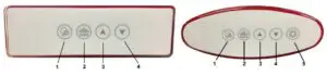
- ON/OFF – Press to start, press again to stop
- PULSE CYCLES – Pressing this button once will turn on Wave Mode which fluctuates the blower fromminimum to maximum power. Pressing the button again changes to Pulse Mode. In Pulse Mode, the blowerwill release air in short, intense bursts. Pressing the button again will return the blower to normal.
- INCREASE SPEED – Press and hold to increase the speed of air flow. Release when desired speed is reached.
- DECREASE SPEED – Press and hold to decrease the speed of air flow. Release when desired speed is reached.
- MOOD LIGHT – Press the button to activate/deactivate the mood light and to cycle through the colors.
Standard Drying Cycle – An automatic drying cycle will start 20 minutes after the blower is turned off. The blower LED blinks while waiting for the purge cycle.
24 Hour Programmable Drying Cycle – The system must be stopped prior to activation or deactivation.
Activation – Determine at which time you wish the purge to activate. At that precise time press and hold
Button 2 on the keypad for 5 seconds. All of the LED lights will flash twice to confirm the activation is complete. The purge cycle will now start at the programmed time every 24 hrs. In the event of a power failure the program will be automatically deactivated.
Deactivion – Press and hold Button 2 for 5 seconds. All of the buttons will flash once to confirm deactivation.
Functioning
- Lateral turbo air ports spaced around the lower side walls of the tub.
- The system functions with a 2 hp blower / 300W air heater that is separate from any other systems.
- This system requires a 20Amp dedicated circuit, 120V.
- The air heater is designed to provide a warm air massage. It is not designed to heat the bath water.
Whirlpool Inline Heater

The inline heater is designed to MAINTAIN the temperature of the bath water between 101-104 degrees Fahrenheit. These limits cannot be increased or decreased. The Heater is operated by a pressure switch which is programmed into the heater. This switch allows the heater to operate only when there is sufficient water flowing through the system.
DO NOT BYPASS THE SWITCH. This option is equipped with a molded plug on the end of a supply cord. Check your local codes and install a 120VAC 20amp GFCI protected dedicated circuit wall outlet within 1.5’ from the heater unit. Plug the cord into the outlet. Every time the whirlpool unit is activated, the heater will activate as well, and will MAINTAIN the water’s temperature between 101 104 F.
Water Heater for Air Bath and Soaker Tubs
The on/off button on the bath tub activates/deactivates the heater. The heater has a built-in 20 minute timer and is a low flow/high efficiency pump, providing silent operation. The option is equipped with a molded plug on the end of a power supply cord. Check your local codes. For the LM305 install a 120 VAC 20amp GFCI and
make sure the GFCI protected dedicated circuit wall outlet is located within 1.5’ from the heater unit. Plug the cord into the outlet. This heater is designed to MAINTAIN the temperature in your bath water between 101- 104 deg Fahrenheit. These temperatures are preset and cannot be adjusted.

Back Massage Functioning – Includes 8 jets that function on an independent 3/4 hp (7.5Amps). 2 jets work at a time cycling up and down your back. This system requires a 20Amp dedicated circuit, 120V.
Back Massage Controls – DO NOT OPERATE the back massage system before you are in the tub and ready for use. Doing so will spray water out of your tub! (1) The push button located at the bottom left of the photo above turns the unit on and off. The large dial (2) on the right will adjust the cycling speed of the jets from completely stopped on 2 active jets, to quickly cycling up and down through the entire back massage system.
Neck Massage Controls – DO NOT OPERATE the neck massage before you are in the tub and ready for use.
Doing so will spray water out of your tub! The middle button (3) is the On/Off button. Pushing the button on the left will adjust the speed of the neck massage jets and set them to pulse simultaneously. Press once for fast, twice for medium, and three times for low speed. The button on the right performs the same function, only with the jets alternating back and forth. Once activated, the neck massage will run on a 20 min timer.
Chromotherapy Mood Light
The ColorGlo LED Multi-Color bath light comes pre-programmed with 10 light modes. To change modes, switch the unit off and then back on within 5 seconds. To resume a lighting mode, leave the unit switched off to save the last lighting mode displayed in memory. That same lighting mode will display the next time the unit is switched on. DO NOT attempt to service the electronic components yourself. Any opening, altering or tampering with this product will void the manufacturer’s warranty. DO NOT submerge the transformer in water or allow it to get wet. Keep the unit dry at all times. DO NOT allow this unit to freeze.
Ozonator
This factory installed option sanitizes your whirlpool. When your whirlpool system is operating your ozonator is generating ozone which is mixed with the re-circulating bath water. The ozone helps neutralize soaps, body oils and other organic and inorganic materials. This unit eliminates the need to run a sanitation solution through the tub’s circulating system.
Solo Touch Control
The Solo Touch system operation and installation information is shown below.
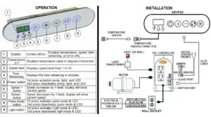
Features:
Pulsating Mode- The pump speed varies automatically with a cycle period of approximately 10 seconds. Speed 10 is the default speed but the keypad will remember the last speed used after being shut down and will automatically revert to that speed. *Wait 5 seconds after powering on the unit to adjust the speed settings*
Laurel Mountain Whirlpools Warranty
This Laurel Mountain Whirlpools bath is warranted to the original purchaser to be free from defects in material and workmanship for the following periods. The bathtub shell carries a limited lifetime warranty. The pump, blower and heater have a limited 10 year warranty. All other parts have a limited 5 year warranty. Proof of purchase is required.
This warranty is issued to the original purchaser and shall be effective from the date of purchase as shown on purchaser’s receipt. Laurel Mountain Whirlpools will repair or replace (at their choice) any unit which proves to be defective in material or workmanship under normal use and service, having been properly installed. This warranty is the only express warranty made by Laurel Mountain Whirlpools and is limited to the duration of this warranty. Any labor charges and/or damage incurred in installation, repair or replacement as well as incidental and consequential damages connected therewith are excluded and will not be paid by Laurel Mountain Whirlpools. Some states do not allow the exclusion or limitation of incidental or consequential damages, so the above limitation or exclusion may not apply to you. This warranty is void for any damage to the bath due to abuse, misuse, neglect, accident, improper installation, any use violating instructions furnished by us, or repair not authorized in writing by Laurel Mountain.