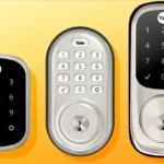
Yale Assure Lock Installation Guide
This manual will walk you through all the required steps to add your new Yale Assure Lock SL to your door.
- Remove Existing Door Hardware
- Double Check Door Measurements
- Install your Assure Lock SL
- Program your Assure Lock SL
- Add your Assure Lock SL to your smart home system or August App*
*If purchased with Yale Smart Module or Connected by August Kit
FAILURE TO FOLLOW THESE INSTRUCTIONS COULD RESULT IN DAMAGE TO THE PRODUCT, VOIDING THE FACTORY WARRANTY AND COULD LEAD TO FAILURE OF THE PRODUCT TO PROVIDE ACCESS.
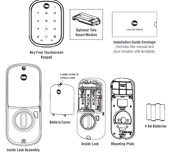
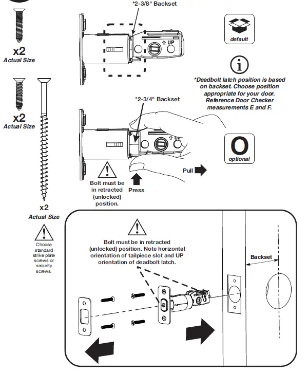
What’s In The Box

(Separates into 3 components)
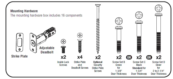 Do not discard old lock hardware until Assure Lock SL has been successfully installed.


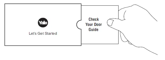
Door Checker
Use door checker from installation guide envelope to verify your door measurements and make any needed adjustments.

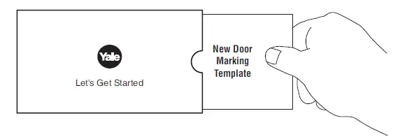
New Door Marking Template
With door checker, use template from installation guide envelope to prep a new door that has not been predrilled for hardware.


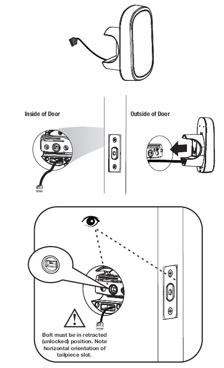


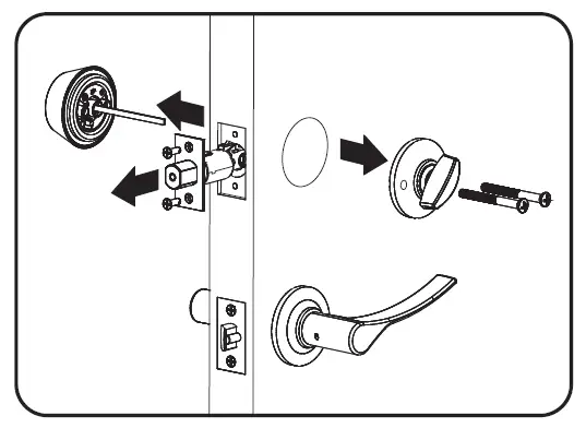
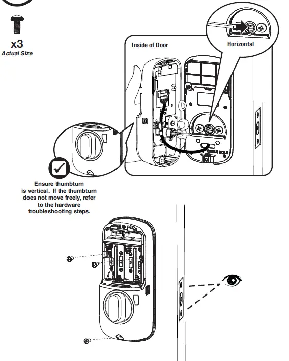
 If thumbturn operation fails, check the installation beginning with Step 3.
 For more information about Yale Smart modules and smart home features visit: https://www.yalehome.com/en/yale/yalehome/residential/yale-smart-home-guide/
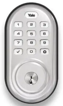
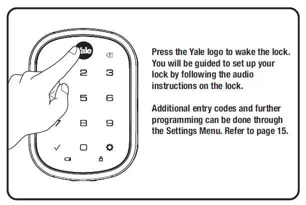
Congratulations, you’ve installed the Yale® Assure Lock® SL Key Free Touchscreen Deadbolt (YRD256)!
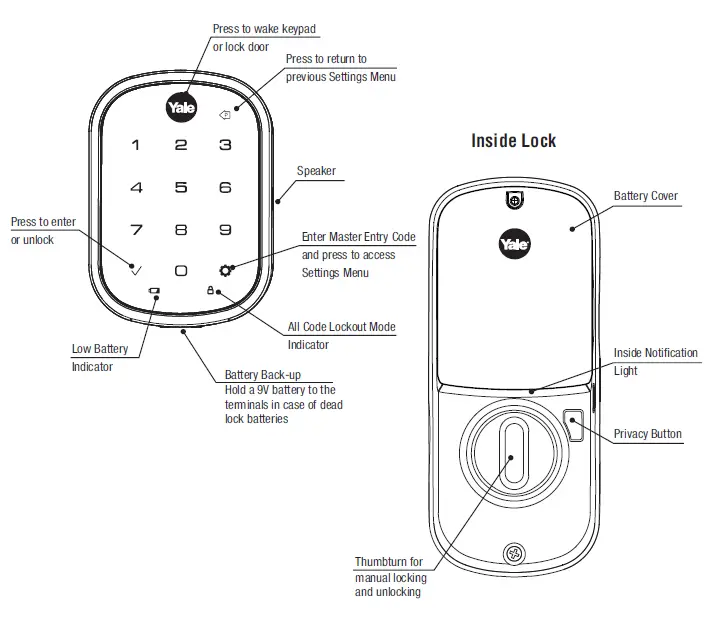
Using Your Lock


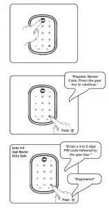
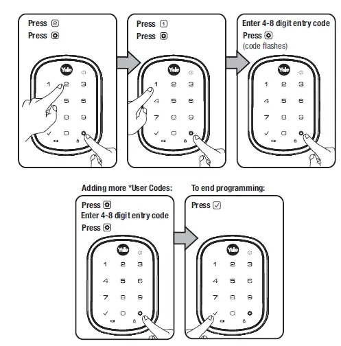
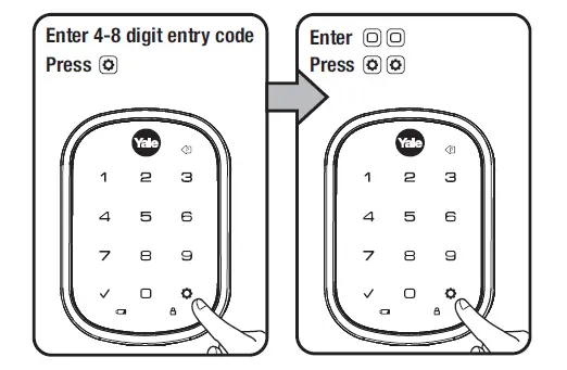
The master entry code is used to change the lock settings
A security best practice is to set your master code with 6 or more digits and create a separate code that is used daily to lock and unlock the door

Master Entry Code must be created first. *Max user codes = 250 with Smart Module; 25 without


Deleting one entry code: To delete all entry codes
To delete one entry code, (Does not delete Master Entry Code):
you must enter the entry
code you wish to delete.

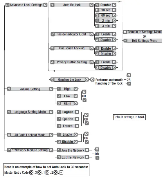
Setting Definitions
| Settings | Default Setting | Definition |
|
Master Entry Code |
Creation required* |
The Master Entry Code is used for programming and for feature settings. It must be created prior to programming the lock. The Master code will also operate (unlock/lock) the lock. |
|
Auto Re-lock |
Disabled |
After a successful code entry or manual unlock with the key, the lock will automatically re-lock after each unlock in an effort to keep your home secure. This feature is optional, and can be turned off. In the ON mode, the lock will automatically re-lock after thirty (30) seconds. |
|
Inside Indicator Light |
Disabled (Off) |
Located on the inside lock. Shows active status (Locked) of lock and can be enabled or disabled in the Advanced Lock Settings (Main Menu selection #3). |
|
One Touch Locking |
Enabled |
When the latch is retracted, activating the keypad will extend the latch (during Auto Re-lock duration or when Auto Re-lock is disabled). When One-Touch Re-lock is not in use (disabled), any valid PIN code will re-lock the lock. |
|
Privacy Button |
Disabled |
Privacy mode is disabled by default. Enable Privacy mode by pressing the privacy button for 4 seconds to put the lock in do- not-disturb mode (all pin codes are disabled). |
|
Volume |
Enabled (Low) |
The volume setting for entry code verification is set to Low (2) by default; otherwise it can be set to High (1) or Silent (3) for quiet areas. |
| Language | English | Choosing English (1), Spanish (2) or French (3) becomes the (default) setting for the lock’s voice prompts. |
|
All Code Lockout Mode |
Disabled |
This feature is enabled by the Master Entry Code. When enabled, it restricts all user (except Master) Entry Code access. When attempting to enter a code while the lock is in All Code Lockout mode, the RED locked padlock will appear on the screen. |
|
Wrong Code Entry Limit |
5 Times |
After five (5) unsuccessful attempts at entering a valid entry code, the lock will shut down and not allow operation for sixty (60) seconds. |
|
Shutdown Time |
60 Seconds |
The Lock will shutdown (flashing RED) for sixty (60) seconds and not allow operation after the wrong code entry limit (5 attempts) has been met. |
*The Master Entry Code must be created prior to any other programming of the lock.
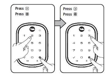
Customizing Lock Through Settings Menu *Master Entry Code Required
- Press Yale logo to wake up lock .
- Enter Master Entry Code* followed by icon.
Lock Response: “Welcome to the Settings Menu. Press each number to hear available settings and then press the settings icon to enter.” - Enter digit corresponding to the function to be performed followed by the icon. Follow the voice commands.

*The Master Entry Code must be created prior to any other programming of the lock.
**Network Module Setting function appears only with Yale Smart module installed.
Troubleshooting
| Symptom | Suggested Action |
|
Lock does not respond – door is open and accessible. |
• Yale keypad becomes active when the Yale logo is pressed. Verify contact with the logo.
• If keypad numbers are visible, check to see if they respond when pressed. • Check batteries are installed and oriented correctly (polarity) in battery case. • Check batteries are in good condition; replace batteries* if batteries are dead. • Check to see if keypad cable is fully connected and is not pinched. |
| Lock does not respond –
door is locked and inaccessible. |
• Batteries may not have enough power. Replace batteries*.
• Apply a 9V battery to terminals below the keypad for backup power option. |
| Lock is on for a while then shows no reaction. Lights dim. | • Batteries do not have enough power. Replace batteries*. |
| Lock chimes to indicate code acceptance, but door will not open. | • Check the door gaps for any foreign objects between door and frame.
• Check that the cable is firmly connected to the inside lock. |
| Lock operates to allow access, but will not automatically re-lock. | • Check to see if Auto Re-lock is enabled.
• Disable Auto Re-lock to lock the door (manually). • If low battery indicator is lit, change batteries*. |
|
Entry codes will not register. |
• Entry codes must consist of 4 to 8 digits.
• The same entry code cannot be used for multiple users. • Management of entry codes is set by the authority of the Master Code, which is set first. Contact the Master user. • Entry codes must be entered within 5 seconds (while keypad is active) or process will have to be restarted. • Check or gear cannot be used as part of the entry code. |
| Upon entering an entry code and pressing key, the lock displays “invalid code” error or lock times out without responding. | • Verify entered code is a valid, previously programmed, 4 to 8 digit code.
• All Code Lockout Mode is enabled. Only the Master Entry Code can enable/disable All Code Lockout Mode. Contact the Master user. |
| Upon entering an entry code and pressing the key, red padlock icon appears and there are different tones. | • Check to see if the lock is set to All Code Lockout Mode. Setting/managing All Code Lockout Mode is done through Master Entry Code only.
Contact Master user. |
| Lock operates, but makes no sound. | • Check to see if Volume is set to Silent (see Feature #4). |
| Lock responds “Low Battery” | • This is the alert to replace the batteries. Replace all four (4) batteries* with new AA Alkaline batteries. |
| Upon entering an entry code and pressing the key, lock responds “Wrong number of digits”. | • The digits entered were incorrect or incomplete. Re-enter the correct code followed by the check key. |
| Lock shows an X on keypad after entering a code. | • Bolt failed to fully retract.
Refer to the “Hardware Troubleshooting” steps on page 21. • Entry code has not been scheduled for use at time of day it is tried. Try entry code again during its scheduled time. |
| Deadbolt does not extend when locking the door with keypad. | • Lock was not handed properly. Rehand lock through settings menu. |
* When batteries are replaced, Smart Module locks have a real time clock that will be set through the User Interface (UI);
it is recommended to verify correct date and time particularly those locks operating under Daylight Saving Time (DST).
Hardware Troubleshooting

If deadbolt does not extend or retract easily when testing thumbturn and keypad operation, revisit inside and keypad installation steps. It is important that the bolt be in the retracted position during lock installations and that installation procedure is followed carefully.
Helpful Tip:
Ensuring smooth deadbolt operation can enhance your battery life.
If you feel resistance, ensure deadbolt strike plate aligns with deadbolt. If deadbolt strike plate is out of alignment, please attempt to adjust
knob/lever/handleset strike using steps below. The knob/lever/handleset latch engagement into the strike is the main component used for door alignment.If deadbolt does not fully extend, consider increasing depth of deadbolt strike pocket in frame.
To adjust Knob/Lever/Handleset strike plate:
- Remove plate from door frame with a manual screwdriver. (Using an electric driver may strip screw heads or enlarge screw holes.)
- Locate strike plate tab. Bend the tab towards surface of strike. Note: a small change may be all that is required
- Reinstall strike plate using a manual screw driver and test again.
- If door cannot be adjusted sufficiently with strike tab, both knob/lever/handleset latch and deadbolt latch could require adjustment – we suggest you
contact a local locksmith for assistance.
For help with misalignments, watch our door alignment video: https://www.yalehome.com/en/yale/yalehome/support/ yrl-electronic-lock-faqs/electronic-lock-installation/
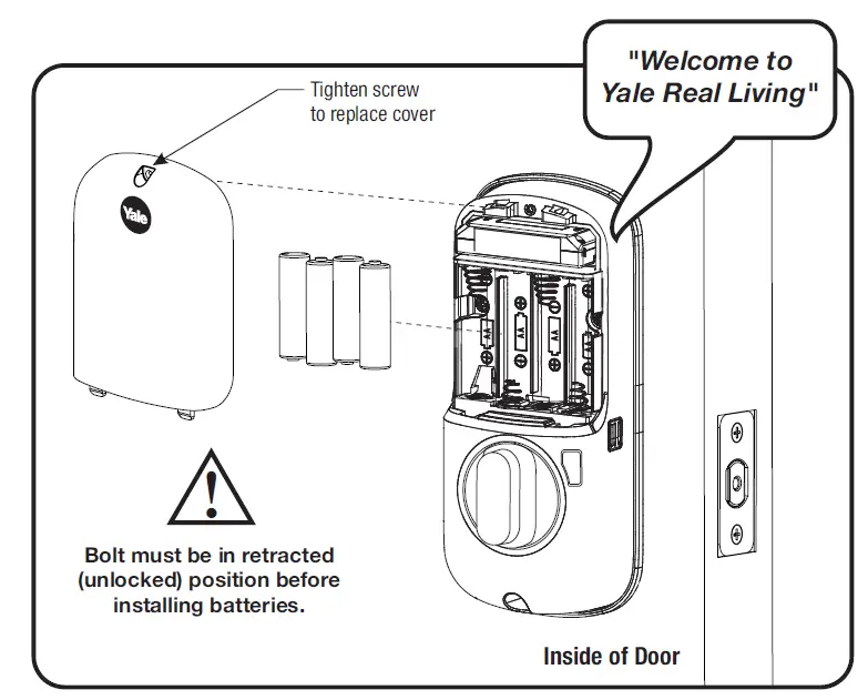
Resetting Lock to Factory Default
When lock is reset to factory defaults all user codes (including the Master Entry code*) are deleted and all programming features are reset to original default settings
(see below).
- Remove the battery cover and batteries.
- Remove the interior side of the lock to access the reset button.
- The reset button (see image at right) is located beside the cable adapter
- While pressing the reset button (minimum of 3 seconds) reinstall batteries. Release reset button.
- Replace battery cover.
Upon reset, Master Entry Code creation is the only option available and must be performed prior to any other programming of the lock.
NOTE TO INSTALLER AND CONSUMER
® While Yale has included several features to prevent lockout (9-Volt battery jumper, low battery warnings), it is still possible for a lockout situation to occur. Because this product does not ® have a mechanical override (a key), Yale recommends to use this product in an environment where there are additional entry points into the dwelling.
FCC:
Class B Equipment
This equipment has been tested and found to comply with the limits for a Class B digital
device, pursuant to Part 15 of the FCC Rules. These limits are designed to provide reasonable protection against harmful interference in a residential installation. This
equipment generates, uses, and can radiate radio frequency energy and, if not installed and used in accordance with the instructions, may cause harmful interference to
radio communications. However, there is no guarantee that interference will not occur in a particular installation. If this equipment does cause harmful Interference to radio
or television reception, which can be determined by turning the equipment off and on, the user is encouraged to try to correct the interference by one or more of the
following measures:
- Reorient or relocate the receiving antenna.
- Increase the separation between the equipment and receiver.
- Connect the equipment into an outlet on a circuit different from that to which the receiver is connected.
- Consult the dealer or an experienced radio/TV technician for help.
Warning: Changes or modifications to this device, not expressly approved by ASSA ABLOY Residential Group could void the user’s authority to operate the equipment
Industry Canada:
This Class A digital apparatus meets all requirements of the Canadian Interference Causing Equipment Regulations.
Please use this procedure only when network primary controller is missing or otherwise inoperable.

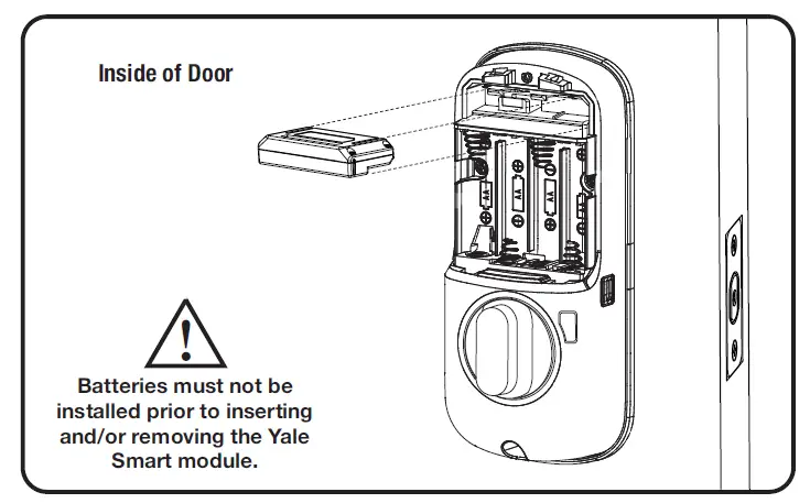
Adding a Yale Z-Wave® Plus v2 Smart Module to your Assure Lock and Z-Wave System
- Install Yale Smart Module into slot above battery compartment
IMPORTANT: Batteries must be removed before inserting Yale Smart Module:

• Remove battery cover
• Remove batteries
• Insert Yale Smart Module
• Reinstall batteries
• Reinstall battery cover - Open Z-Wave system’s smart home or alarm app on your smartphone or tablet
- If you have Smart Start* enabled with your Z-Wave System follow in-app prompts to add a new device If you don’t have smart start or are not sure, follow steps 4 – 6
- On your lock keypad, enter your master entry code followed by the
 icon
icon - Press the 7 key followed by the
 icon
icon - Press the 1 key followed by the
 icon
icon
Removing a Yale Z-Wave® Plus v2 Smart Module from your Assure Lock and Z-Wave System
- Open Z-Wave system’s smart home or alarm app and follow instructions for removing a device

- On your lock keypad, enter your master entry code followed by the icon
- Press the 7 key followed by the icon
- Press the 3 key followed by the icon
- Remove Yale Smart Module from slot above battery compartment
IMPORTANT: Batteries must be removed before removing Yale Smart Module:
• Remove battery cover
• Remove batteries
• Remove Yale Smart Module
• Reinstall batteries
• Reinstall battery cover
*SmartStart enabled products can be added into a Z-Wave network by scanning the Z-Wave QR Code present on the product with a controller providing SmartStart
inclusion. No further action is required and the SmartStart product will be added automatically within 10 minutes of being switched on in network vicinity
 Warning: Changes or modifications to this device, not expressly approved by ASSA ABLOY Residential Group could void the user’s authority to operate the equipment.
This device is a security enabled Z-Wave Plus v2 product that is able to use encrypted Z-Wave Plus v2 messages to communicate to other security enabled Z-Wave Plus v2 products. This device must be used in conjunction with a Security Enabled Z-Wave Controller in order to fully utilize all implemented functions. This product can be operated in any ZWave network with other Z-Wave certified devices from other manufacturers. All non-battery operated nodes within the network will act as repeaters regardless of vendor to increase reliability of the network.
FCC:
Class B Equipment
This equipment has been tested and found to comply with the limits for a Class B digital device, pursuant to Part 15 of the FCC Rules. These limits are designed to provide reasonable protection against harmful interference in a residential installation. This equipment generates, uses, and can radiate radio frequency energy and, if not installed and used in accordance with the instructions, may cause harmful interference to radio communications. However, there is no guarantee that interference will not occur in a particular installation. If this equipment does cause harmful Interference to radio or television reception, which can be determined by turning the equipment off and on, the user is encouraged to try to correct the interference by one or more of the following measures:
- Reorient or relocate the receiving antenna.
- Increase the separation between the equipment and receiver.
- Connect the equipment into an 4itlet on a circuit different from that to which the receiver is connected.
- Consult the dealer or an experienced radio/TV technician for help.
THIS DEVICE COMPLIES WITH PART 15 OF THE FCC RULES. OPERATION IS SUBJECT TO THE FOLLOWING TWO CONDITIONS. (1) THIS DEVICE MAY NOT CAUSE HARMFUL INTERFERENCE, AND (2) THIS DEVICE MUST ACCEPT ANY INTERFERENCE RECEIVED, INCLUDING INTERFERENCE THAT MAY CAUSE UNDESIRED OPERATION.
This equipment complies with FCC radiation exposure limits set forth for an uncontrolled environment. This equipment should be installed and operated with minimum distance 20cm between the radiator & your body.
Industry Canada:
Section 7.1.2 of RSS-GEN Under Industry Canada regulations, this radio transmitter may only operate using an antenna of a type and maximum (or lesser) gain approved for
the transmitter by Industry Canada. To reduce potential radio interference to other users, the antenna type and its gain should be so chosen that the equivalent isotropically radiated power (e.i.r.p.) is not more than that necessary for successful communication.
Yale Z-Wave+ Product Info
- Manufacturer ID: Assa Abloy (0x0129)
- Z-Wave Device Type: Door Lock Keypad
- Z-Wave Role Type: Listening Sleeping Slave (LSS)
- Product ID: 0xA570
- Product Type ID: 0x8002 for YRD256-ZW3 (Touch Screen Deadbolt)
Supported Command Classes
- Command Class Z-Wave+ Info
- Command Class Manufacturer Specific*
- Command Class Security
- Command Class Security 2
- Command Class Device Reset Locally*
- Command Class Power Level*
- Command Class Version
- Command Class Battery*
- Command Class Door Lock*
- Command Class Door Lock Logging*
- Command Class Schedule Entry Lock*
- Command Class User Code*
- Command Class Time Parameters*
- Command Class Time*
- Command Class Firmware Update Meta Data*
- Command Class Association*
- Command Class Multi Channel Association*
- Command Class Association Group Info*
- Command Class Notification*
- Command Class Configuration*
- Command Class Application Status
- Command Class Transport Service
- Command Class Supervision
- Command Class Indicator*
* Command Class Requires Security
Association Table:
Table 1 – Association Table
| Group ID | Maximum Nodes | Description | Commands |
| 1 | 1 | Lifeline | · Command_Class_Battery |
| o Battery_Report
· Command_Class_Configuration o Configuration_Report · Command_Class_Notification o Notification_Report · Command_Class_Door_Lock o Door_Lock_Operation_Report o Door_Lock_Configuration_Report · Command_Class_Device_Reset_Locally o Device_Reset_Locally_Notification · Command_Class_Indicator o Indicator_Report · Command_Class_User_Code o User Code Report · Command_Class_Clock o Clock_Report |
Notifications Table
|
Alarm Reports |
Alarm type | Alarm Level |
Description |
Notification Type |
Event |
|
Deadbolt Jammed |
0x09 |
0x01 |
Deadbolt
jammed while locking |
0x06 |
0x0B |
|
0x02 |
Deadbolt
jammed while unlocking |
0x06 |
0x0B |
||
|
Keypad Lock |
0x12 |
0x (01 – max users) | Where Alarm level represents user slot number |
0x06 |
0x05 |
|
Keypad Unlock |
0x13 |
0x(01- max users) |
Where Alarm level represents user slot number (0x00 =
Master Code) |
0x06 |
0X06 |
|
Manual Lock |
0x15 |
0x01 |
by key cylinder
or inside thumb- turn |
0x06 |
0x01 |
|
0x02 |
by touch function (lock
and leave) |
0x06 |
0x01 |
|
0x03 |
By inside button |
0x06 |
0x01 |
||
|
Manual Unlock |
0x16 |
0x01 |
By key cylinder or inside thumb
turn |
0x06 |
0x02 |
|
RF Operate Lock |
0x18 |
0x01 |
by RF module |
0x06 |
0x03 |
| RF Operate Unlock |
0x19 |
0x01 |
by RF module |
0x06 |
0X04 |
| Auto Lock Operate Locked |
0x1B |
0x01 |
Auto re-lock cycle complete, locked. |
0x06 |
0x09 |
|
User deleted |
0x21 |
0x(01-
max users) |
User was deleted. Alarm level = user slot
number |
0x06 |
0X0D
(single) 0X0C (all) |
|
Door State |
0x23 |
0x00 |
Door is open |
0x06 |
0x16 |
|
0x01 |
Door is closed |
0x06 |
0x17 |
||
|
Non Access |
0x26 |
0x(01- max users) |
A Non Access Code was entered at the lock.
Where alarm level represents user slot number |
0x06 |
0xFE |
| Daily Repeating Schedule Set/Erased |
0x60 |
0x(01-
max users) |
Schedule(s) has been set/erased for specified
user ID |
0x06 |
0xFE |
| Year Day Schedule Set/Erased |
0x62 |
0x(01-
max users) |
Schedule(s) has been set/erased for specified
user ID |
0x06 |
0xFE |
|
All Schedule Types Enabled/Disabled |
0x65 |
0x(01- max users) |
Schedule(s) has been enable/disabled
for specified user ID |
0x06 |
0xFE |
|
Master Code changed |
0x70 |
0x00 |
Master code was
changed at keypad |
0x06 |
0x12 |
| 0xFB | Master code was changed over RF | 0x06 | 0x0E | ||
|
User added |
0x(01-
max users) |
User added. Alarm level = user slot
number |
0x06 |
0X0E |
|
|
Duplicate Pin- code error |
0x71 |
0x (01- max users) |
Where Alarm level represents user slot number
Alarm generated in response to add user RF cmd. This alarm is not generated when attempting to add duplicate pin at the keypad. The lock simply denies it and plays the “ Denied”. Trying to duplicate the master code will result in a 0x71 0x00 alarm report. |
0x06 |
0x0F |
| Disabled user entered at keypad |
0x83 |
0x(01-
max users) |
A disabled user pin code was entered at the
keypad |
0x06 |
0xFE |
|
Valid user but outside of schedule |
0x84 |
0x(01- max users) |
A valid user can be both a normal user and a Non-Access user. If a non- access user is out of schedule this alarm will be sent instead of the non-
access alarm. |
0x06 |
0xFE |
|
Tamper Alarm |
0xA1 |
0x01 |
keypad attempts
exceed code entry limit |
0x06 |
0X10 |
|
0x02 |
front escutcheon removed from main |
0x06 |
0xFE |
||
|
Battery is fully charged |
0x80 |
0x05 |
After a low battery alert was observed, the lock was powered down and powered back up with full
battery. |
0x08 |
0x0D |
|
Door Lock needs Time set |
0x82 |
0x00 |
Power to the lock was restored and the locks RTC was cleared. The controller should set the time to
ensure proper logging. |
0x08 |
0x01 |
|
Low Battery Alarms*** |
0xA7 |
0x(Current
%) |
Low Battery
(Starting at 4.0V) |
0x08 |
0x0A |
|
0xA8 |
0x(Current
%) |
Critical Battery Level (Starting at 3.9V) |
0x08 |
0x0B |
** The Yale lock also supports a 3rd low battery alarm: too low to operate. This
alarm is sent out as a Battery Report (with value = 0xFF) through the Battery
Command Class. This is the last low battery alarm level before the product stops
functioning.
|
Param. Num. |
Name |
Length |
Configuration Properties |
Info |
Info String | ||
| Min | Max | Default | |||||
|
1 |
Volume |
1 byte |
0x01
(High Volume) |
0x03 (Silent) |
0x02 (Low Volume) |
Set Volume Level to high (1), low (2), or silent (3). |
53 |
|
2 |
Auto Relock |
1 byte |
0x00
(Disable) |
0xFF
(Enable) |
0x00
(Disable) |
Set Auto Relock feature to enable or disable. |
45 |
|
3 |
Relock time |
1 byte |
0x0A (10
seconds) |
0xB4 (180
seconds) |
0x1E (30
seconds) |
Adjust the time your lock will auto relock. |
43 |
|
4 |
Wrong Code Entry Limit |
1 byte |
0x03 |
0x0A |
0x05 |
Adjust the limit for wrong code entries allowed by your lock. |
61 |
|
5 |
Language |
1 byte |
0x01 (English) |
0x03 (French) |
0x01 (English) |
Set the language to English (1), Spanish (2), or French
(3). |
60 |
|
7 |
Shut down time |
1 byte |
0x0A (10 seconds) |
0x84 (132 seconds) |
0x3C (60 seconds) |
Adjust the time your lock is shutdown after reaching its wrong code entry limit. |
80 |
|
8 |
Operating mode |
1 byte |
0x00
(Normal Mode) |
0x02
(Privacy Mode) |
0x00
(Normal Mode) |
Set the Operating Mode to normal mode(0), vacation mode(1) or privacy mode(2). |
75 |
|
11 |
One Touch Locking |
1 byte |
0x00
(Disable) |
0xFF
(Enable) |
0xFF
(Enable) |
Set One Touch Locking feature to enable or disable. |
51 |
|
12 |
Privacy Button |
1 byte |
0x00
(Disable) |
0xFF
(Enable) |
0x00
(Disable) |
Set Privacy Button feature to enable or disable. |
48 |
|
13 |
Lock Status LED |
1 byte |
0x00
(Disable) |
0xFF
(Enable) |
0x00
(Disable) |
Set Lock Status LED feature to enable or disable. |
57 |
|
15 |
Reset To Factory Defaults |
1 byte |
0x01 |
0x01 |
N/A |
Lock will reset to factory defaults when set this parameter to 0x01. |
57 |