OLUTRON PD4-16-F Lighting Control Panels
DIN Panels and Accessories
The Lutron myRoom and HomeWorks families of DIN rail panels are designed to accept DIN Power Modules (DPMs). The DPMs can be configured in the panel to control multiple load types to fit the size, lighting plan and design of the space.
Features
- Panels house up to four DIN Power Modules (DPMs) or up to three DIN Power Modules (DPMs) and one QSPS power supply.
- Compatible DPMs
- Digital Controllers
- LQSE-2ECO-D
- LQSE-2DAL-D
- Dimming
- MQSE-4A1-D
- MQSE-3A1-D
- MQSE-2A1-D
- LQSE-4A1-D
- LQSE-4T5-120-D
- QSNE-4T10-D
- LQSE-4T10-D
- Switching
- MQSE-4S1-D
- MQSE-3S1-D
- MQSE-2S1-D
- LQSE-4S5-230-D
- LQSE-4S8-120-D
- QSNE-4S10-D
- LQSE-4S10-D
- Power Supplies and Motor Controllers
- MQSPS-DH-1-30 (requires MQSPS-BRK)
- QSPS-DH-1-75-H
- LQSE-4M-D
- Feed-through panel.
- Panels extensively tested to ensure optimal thermal performance with maximum load in 32 °F to 104 °F (0 °C to 40 °C) ambient environment.
- Panels are rated for 120–240 V~ ULR, CE and non-CE applications.
Models Available
- PD4-16-F
120–240 V~ Non-CE
Line / Mains Voltage Enclosure - PD4-16-F-CE
220–240 V~ CE
Line / Mains Voltage Enclosure
Specifications
Regulatory Approvals PD4-16-F model only
- Complies with ULR 508
- Complies with CSA C22.2, #14
- Complies with NMX-J-515-ANCE-2008
PD4-16-F-CE model only
- Complies with EN 50178
Power
- 120 –240 V~ 50/60 Hz
Environment
- Mount where ambient temperature is 32 °F to 104 °F (0 ºC to 40 ºC). Relative humidity 0%–90%, non-condensing.
- Indoor use only.
- Passive cooling.
- International Protection Marking: IP20
Mounting
- Surface-mount only.
- Enclosure with a maximum number of DPMs installed generates heat, maximum 140 BTUs / hour.
- Meets NEC® requirements for installation in “other space used for environmental air”.
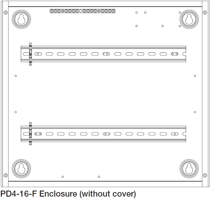
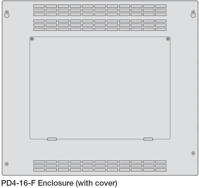
Construction
- 16-gauge (1.5 mm) powder-coated sheet metal enclosure.
- 16-gauge (1.5 mm) powder-coated metal cover with ventilation holes and hinged access door. Cover is attached using four Phillips-head screws.
- Includes two DIN rails for mounting DPMs or power supplies.
Line / Mains Voltage Connections
- Wires land directly on DPMs or power supplies.
- Modules in the panel can be wired using one power feed or up to four power feeds. If feeding through Lutron power modules using Line / Mains terminals, the total load current must be less than or equal to 15 A. It is recommended that all feed splicing be done outside of this enclosure.
Grounding Terminals
- 15 position aluminum ground bar (PD4-16-F)
- 23 position copper ground bar (PD4-16-F-CE)
Capacity
- Enclosure can accommodate 4 DPMs or power supplies.
Mounting for Panels
- For indoor use only.
- Surface-mount only.
- Install in accordance with all local and national electrical codes.
- Equipment is passively air-cooled.
- Panels weigh up to 30 lb (14 kg). Reinforce wall structure for weight and local codes.
- Use keyholes with bolts sufficient for 30 lb (14 kg) load, 1/4 in (M6) bolts recommended.
- Mount panel(s) within 7º of true vertical.
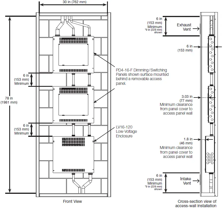
- Leave 6 in (153 mm) clearance on each side of panel.
- Mount in a location where the cover will not be blocked. 12 in (304 mm) of clearance is recommended in front of the panel, however a minimum of 3.03 in (77 mm) can be achieved: see Wall Cavity Mounting guidelines for more information.
- Panel can be installed in a minimum of 8.125 cubic feet (0.23 cubic meter) of confined space providing intake and exhaust venting requirements are met. See Wall Cavity Mounting section for details.
- Mount panel so Line / Mains voltage wiring is at least 6 ft (1.8 m) from sound or electronic equipment and wiring.
- Mount panel where audible noise is acceptable (internal relays on modules click).
- Panel(s) should be a minimum of 6in (153mm) from the floor and ceiling.
- Panel can be installed above a suspended ceiling. See Suspended Ceiling Installation section for details.
- Consult Dimensions page for panel size, conduit knockouts, and mounting hole locations.
Panel Stacking
- Do not mount more than two PD4-16-F panels vertically.
- A single LV16 panel may be installed under as many as two PD4-16-F panels.
- A minimum vertical spacing of 6 in (153 mm) is required between each panel.
- If stacking two PD4-16-F panels above an LV16 panel, PDUs should only be provided by the LV16 panel. No PDUs should be provided by any modules located in the PD4-16-F panels.
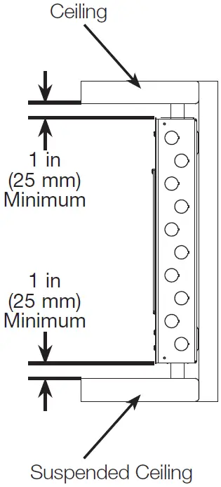
Suspended Ceiling Installation
- Panel(s) can be a minimum of 1 in (25 mm) from the top of the suspended ceiling and ceiling.
- Panels cannot be vertically stacked when installed above a suspended ceiling.
- Maintain 12 in (304 mm) of clearance in front of panel when mounting in a suspended ceiling.

NOTE: Installation must comply with all working space requirements. Consult with your jurisdiction for local requirements.
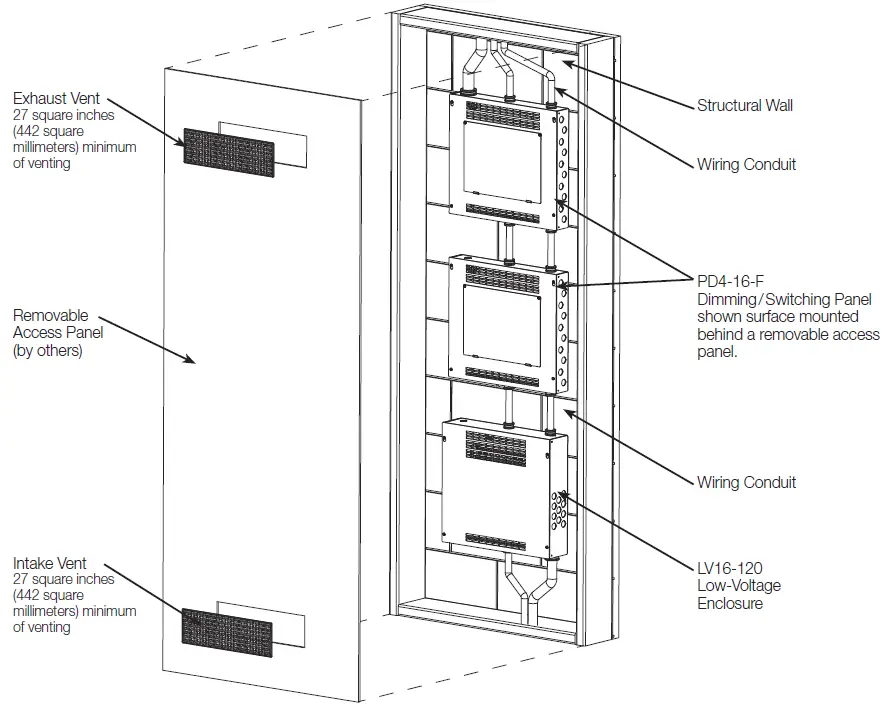
Wall Cavity Mounting
In addition to the Panel Mounting requirements found in this document, the following is required when mounting panels into a wall cavity.
- Wall Cavity Mounting requires a minimum of 8.125 cubic feet (0.23 cubic meter) of confined space.
- This confined space requires a minimum of 27 square inches (442 square millimeters) of venting (area of vent openings / aperture) for each of the intake and exhaust vents.
- Intake vent must be located below the bottom panel while the exhaust vent must be located above the top panel.
- The confined space must have a Removable Access Panel large enough to service the equipment.
- Panels should only be surface-mounted.
- Panels should be mounted a minimum of 6 in (153 mm) from the floor and 6 in (153 mm) from the ceiling to ensure proper ventilation.
NOTE: Installation must comply with all working space requirements. Consult with your jurisdiction for local requirements.
NOTE: Installation must comply with all working space requirements. Consult with your jurisdiction for local requirements.
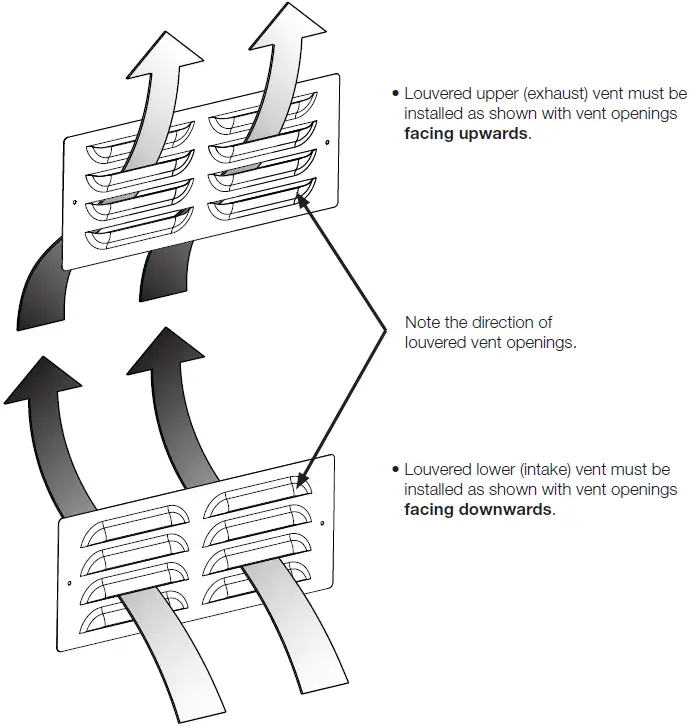
Vent orientation: Proper venting is required to cool equipment correctly when installed behind a removable access panel. If louvered vents are used, they must be installed as shown below to allow required air flow and cooling. A minimum of 27 square inches (442 square millimeters) of venting (area of vent openings / aperture) required for each of the intake and exhaust vents.
Panel Dimensions
All dimensions shown as: in (mm)
![]()