APC BN450MNW Battery Back-Up and Surge Protector

Safety and General Information
Inspect the package contents upon receipt. Notify the carrier and dealer if there is any damage.
SAVE THESE INSTRUCTIONS
This section contains important instructions that should be followed during installation and maintenance of the UPS and batteries.
DANGER
RISK OF ELECTRIC SHOCK, EXPLOSION, OR ARC FLASH
- This UPS is intended for indoor use only.
- Do not operate this UPS in direct sunlight, in contact with fluids, or where there is excessive dust or humidity.
- Connect the UPS power cable directly to a wall outlet.
- Be sure the air vents on the UPS are not blocked. Allow adequate space for proper ventilation.
Failure to follow these instructions will result in death or serious injury.
CAUTION: A battery can present a risk of electric shock and burns by high short-circuit current.
CAUTION: Failed batteries can reach temperatures that exceed the burn thresholds for touchable surfaces.
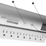
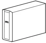
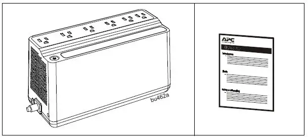
Inventory
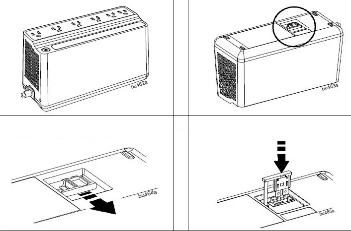
Connect the Battery
The Back-UPS is shipped with one battery cable disconnected.
- Remove the “Stop! Connect the Battery” label that covers the outlets.
- The battery connector is located on the underside of the unit.
- Slide the battery connector handle away from its disconnected position.
- Turn the battery connector to a 90-degree upright position and push it into the unit.
Specifications
| Model | BN450MNW | |
| Input | Voltage | 120 Vac Nominal |
| Frequency | 50/60 Hz + 1 Hz auto-sensing | |
| Brownout Transfers | 92 Vac Typical | |
| Over-voltage Transfer | 139 Vac Typical | |
| Output | UPS Capacity | 450 VA, 255 W |
| No. of Outlets | 6 | |
| Battery Backup / Surge Outlets | 4 / 2 | |
| Total output current | 6 A | |
| Voltage – On Battery | 115 Vac ± 8% | |
| Frequency – On Battery | 50/60 Hz + 1 Hz | |
| Transfer Time | 4 ms Typical | |
| Protection and Filtering | EMI/RFI Filter | Full time |
| AC Input | Resettable circuit breaker | |
| Battery | Type | Sealed, maintenance-free, lead acid, 12 V |
| Average Life | 3 – 5 years, the number of discharge cycles, poor quality AC power, environmental temperature and humidity may shorten the battery lifetime | |
| Charging Time | 8 hours | |
| Model | BN450MNW | |
| Physical | Net Weight | 5.7 lb (2.6 kg) |
| Dimensions LxWxH | 9.98 in x 4.13 in x 5.51 in
25.35 cm x 10.5 cm x 14.02 cm |
|
| Operating Temperature | 32 ºF to 104 ºF (0 ºC to 40 ºC) | |
| Storage Temperature | -4 ºF to 122 ºF (–20 ºC to 50 ºC) | |
| Operating Relative Humidity | 0 to 95% non-condensing humidity | |
| Operating Elevation | 0 to 10,000 ft (0 to 3000 m) | |
| International Protection Code | IP20 | |
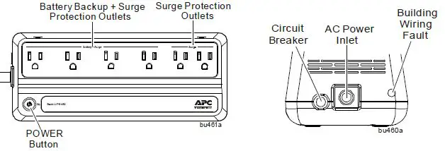
Connect Equipment
| Feature | Function | Suggested Use |
| Battery Backup + Surge Protection Outlets | Receive power from the battery for a limited period of time when a power outage, or brownout condition occurs. Help to provide protection from
power surges or spikes. |
Connect a computer, monitor and other essential peripheral devices that need to remain on during power outages or AC
problems. |
| Surge Protection Outlets | Help to provide protection from power surges or spikes. | Connect non-essential peripheral devices (such as printer, scanner, etc.) that do not need to remain on during power outages or AC
problems. |
Turn On the Back-UPS
Press the POWER button. It will illuminate green and a single short beep indicates that the Back-UPS is on and helping to provide protection for connected equipment. The Back-UPS battery will charge regardless of whether the Back-UPS is switched on or off as long as it is connected to AC power. The UPS will have full runtime capability after the initial 24-hour charging period, connected to AC power. If the Building Wiring Fault indicator (located on the end near the power cord) is illuminated red, your building wiring may present a shock hazard that should be corrected by a qualified electrician.
Turn Off the Back-UPS
Press the POWER button for at least 2 seconds. At the first beep, release the button and the UPS will turn off. A 2 second delay has been added to mitigate unintentional contact with the POWER button.
Quick Mute
User correctable audible alarms such as On Battery can be temporarily muted. Short press (less than 2 seconds) the POWER button to temporarily mute the audible alarm until the condition is reset. A short double beep confirms that Quick Mute is been activated. Pressing the POWER button for more than 2 seconds will turn off the UPS. Other critical events such as Battery replacement and Charger notification can not be temporarily muted. In such cases, the unit must be turned off.
On Battery Indicator Modes
Press and hold the POWER button till a third beep is heard while the UPS is turned ON, to configure the On Battery Indication mode. At the third beep, POWER button will illuminate red and green alternately. Release the POWER button and the illumination color indicates the mode in which the UPS is in. Press the POWER button again to cycle through each mode. Refer the table below for the details of each mode selection color. Once the mode is selected, wait for 5 seconds to set the configuration.
| Mode | Visual Indicator | Audible Indicator | Mode Selection Color |
| Quiet Alarm (default) | The POWER button is solid green and flashes twice every 2 seconds until Low Battery notification where it will flash green in rapid succession. | No alarm until Low Battery notification where the alarm beeps twice every 30 seconds | Flashing green |
| No Alarm | No alarm while the UPS is On Battery | Flashing red | |
| Full Alarm | Alarm sounds 4 beeps every 30 seconds until Low Battery notification where the alarm beeps every half second. As the UPS shuts down, it sounds one beep every 4
seconds |
Flashing amber |
Voltage Sensitivity Adjustment (optional)
The Back-UPS detects and reacts to line voltage distortions by transferring to battery backup power to help protect connected equipment. In situations where either the Back-UPS or the connected equipment is too sensitive for the input voltage level it is necessary to adjust the transfer voltage.
- Turn off the UPS while connected to a wall outlet.
- Press and hold the POWER button for 10 seconds. The POWER button will illuminate green and red alternately to indicate that the Back-UPS is in Program mode.
- The POWER button will flash either green, amber, or red to indicate the current sensitivity level. Refer to the table for an explanation of the transfer voltage sensitivity levels.
- To exit Program mode wait five seconds and all LED indicators will extinguish. Program mode is no longer active.
| LED
Flashes |
Sensitivity Setting | Input Voltage Range (AC Operation) | Recommended Use |
| Green | LOW | 88 Vac to 142 Vac | Use this setting with equipment that is less sensitive to fluctuations in voltage or waveform distortions. |
| Red | MEDIUM | 92 Vac to 139 Vac | Factory default setting. Use this setting under normal conditions. |
| Amber | HIGH | 96 Vac to 136 Vac | Use this setting when connected equipment is sensitive to voltage and waveform fluctuations. |
Status Indicators
| Status | Power Button illumination | Audible Indicator On | Audible Indicator Terminates |
| Power On
The Back-UPS is supplying AC power to connected equipment. |
Solid green | None | N/A |
| On Battery
Back-UPS supplying battery power to battery backup outlets. |
Solid green and flashes twice every 2 seconds. | The audible alarm depends on the On Battery Indicator mode setting. See the On Battery Indicator Modes section for full details. | – Using Quick Mute
– Beeping stops when AC power is restored or the Back-UPS is turned off. Applies only to modes where the on battery alarm is audible. |
| Low Battery notification
The Back-UPS is supplying battery power to the battery backup outlets and the battery is near a total discharge state. |
Flashes green in rapid succession. | ||
| Low Battery shutdown
The battery has been completely discharged while the Back-UPS is on battery, the UPS will shut down. |
None | – AC power is restored
– AC is not restored within 32 seconds – The Back-UPS is turned off. |
|
| Sleep Mode
The UPS has shut down and will “awaken” once AC power is restored |
None | None | N/A |
| Replace Battery
• The battery is disconnected. • The battery needs to be charged, or replaced. |
Alternates green-red |
Constant tone |
– Back-UPS is turned off
– If battery is disconnected, unplug the Back-UPS from AC source and then turn it off. Refer to the section “Connect the Battery” on page 2. – If battery needs replacement, refer to the section “Battery Replacement” on page 8 for details. |
| Detected Overload
An overload condition has occurred in one or more of the battery backup outlets while operating on battery power. |
None | Constant tone | Back-UPS is turned off |
Troubleshooting
| Problem and Possible Cause | Solution |
| The Back-UPS will not turn on | |
| The Back-UPS is not connected to AC power, there is no AC power available at the wall outlet, or the AC power is experiencing a
brownout or over voltage condition. |
Be sure the power cord is securely connected to the wall outlet, and AC power available at the wall outlet.Where ever applicable, be sure that
the wall outlet is switched on. |
| The Back-UPS is on, the POWER button illuminates green and red alternately and the unit emits a constant tone | |
| • The battery is disconnected.
• The battery is near the end of useful life and should be replaced. |
• Remove AC power and refer to the section
“Connect the Battery” on page 2. • Refer to the section “Battery Replacement” on page 8 for details. |
| Connected equipment loses power | |
| A Back-UPS overload condition has occurred. | Remove all nonessential equipment connected to the outlets. Reconnect equipment one at a time to the Back-UPS.
Charge the battery for 24 hours to make sure it is fully charged. If the overload condition still persists, replace the battery. |
| The Back-UPS battery is completely discharged. | Connect the Back-UPS to AC power and allow the battery to recharge for eight hours. |
| Connected equipment does not accept the step-approximated sine waveform from the Back-UPS. | The output waveform is intended for computers and peripheral devices. It is not intended for use with motor driven equipment. |
| The Back-UPS may require service. | Contact SEIT Technical Support. |
| The POWER button illuminates green and flashes twice every 2 seconds. | |
| The Back-UPS is operating on battery power. | The Back-UPS is operating normally on battery power. Save all open files, and shutdown the computer. When AC power is restored the
battery will recharge. |
| The POWER button flashes green in rapid succession. | |
| The Back-UPS battery has approximately two minutes of remaining runtime. | The battery is near a total discharge state. Save all open files, and shutdown the computer.
When AC power is restored the battery will recharge. |
| The Building Wiring Fault LED illuminates red | |
| The building wiring presents a shock hazard that must be corrected by a qualified
electrical. |
Do not operate the Back-UPS. Call a qualified electrician to correct the building wiring fault. |
| The Back-UPS has an inadequate battery runtime | |
| • The battery is not fully charged.
• The battery is near the end of useful life and should be replaced. |
Leave the Back-UPS connected to AC power for eight hours while the battery charges to full capacity.
As a battery ages, the runtime capability decreases. See “Battery Replacement” on page 8 to order replacement batteries. |
| The alarm is on with a constant tone; outlets are normal but POWER button illumination is not bright. | |
| The UPS is on AC power but the power of the connected equipment exceeds the rated power of the UPS. If a power disruption occurs the UPS may not be able to power the connected equipment. Power to the outlets will be uninterrupted as long as AC power is present. | Disconnect devices from the UPS until the load is less than the rated output of the UPS. |
| Problem and Possible Cause | Solution |
| The alarm is on with a constant tone and the UPS is off. | |
| The UPS was on battery and the connected load exceeded the rated load of the UPS. | Turn off the UPS. Disconnect all devices. Turn on the UPS and reconnect the devices one at a time. |
Wall Mount Installation
- Horizontal installation, use 2 screws 7.63” (194 mm) apart.
- Allow 5/16” (8 mm), of the screw to protrude from the wall.
Service
If the unit requires service, do not return it to the dealer. Follow these steps:
- Review the Troubleshooting section of the manual to eliminate common problems.
- If the problem persists, contact Schneider Electric IT (SEIT) Customer Support through the APC by Schneider Electric Web site, www.apc.com.
- Note the model number and serial number and the date of purchase. The model and serial numbers are located on the rear panel of the unit and are available through the LCD display on select models.
- Call SEIT Customer Support and a technician will attempt to solve the problem over the phone. If this is not possible, the technician will issue a Returned Material Authorization Number (RMA#).
- If the unit is under warranty, the repairs are free.
- Service procedures and returns may vary internationally. Refer to the APC by Schneider Electric Web site for country specific instructions.
- Pack the unit in the original packaging whenever possible to avoid damage in transit. Never use foam beads for packaging. Damage sustained in transit is not covered under warranty.
- Always DISCONNECT THE UPS BATTERIES before shipping. The United States Department of Transportation (DOT), and the International Air Transport Association (IATA) regulations require that UPS batteries be disconnected before shipping. The internal batteries may remain in the UPS.
- Write the RMA# provided by Customer Support on the outside of the package.
- Return the unit by insured, pre-paid carrier to the address provided by Customer Support.
Battery Replacement
CAUTION
- Replace the battery at least every 5 years or at the end of its service life, whichever is earlier.
- Replace the battery immediately when the UPS indicates battery replacement is necessary.
- Replace batteries with the same number and type of batteries as originally installed in the equipment.
- Replace the battery immediately when the UPS indicates a battery over-temperature condition, or when there is evidence of electrolyte leakage. Power off the UPS, unplug it from the AC input, and disconnect the batteries. Do not operate the UPS until the batteries have been replaced.
Failure to follow these instructions can result in minor or moderate injury and equipment damage.
The battery in the Back-UPS is not user-replaceable. Contact SEIT Technical Support for a list of authorized service centers near you.
- Servicing of batteries should be performed or supervised by personnel knowledgeable about batteries and required precautions.
- For the recycling battery information, please go to apc.com/recycle.
Register your product on-line. http://warranty.apc.com
The standard warranty is three (3) years from the date of purchase. Schneider Electric IT (SEIT) standard procedure is to replace the original unit with a factory reconditioned unit. Customers who must have the original unit back due to the assignment of asset tags and set depreciation schedules must declare such a need at first contact with an SEIT Technical Support representative. SEIT will ship the replacement unit once the defective unit has been received by the repair department, or cross ship upon the receipt of a valid credit card number. The customer pays for shipping the unit to SEIT. SEIT pays ground freight transportation costs to ship the replacement unit to the customer.
APC by Schneider Electric IT Customer Support Worldwide
For country specific customer support, go to the APC by Schneider Electric Web site, www.apc.com.
EMC Compliance
This device complies with part 15 of the FCC rules. Operation is subject to the following two conditions: (1) This device may not cause harmful interference, and (2) This device must accept any interference received, including interference that may cause undesired operation. Select models are compliant with California (CEC) Battery Charger regulations. For more information on your specific model visit the APC by Schneider Electric web site, www.apc.com .
© 2021 APC by Schneider Electric. APC, the APC logo, and Easy UPS are owned by Schneider Electric Industries S.A.S., or their affiliated companies. All other trademarks are property of their respective owners.