Fuse Layout Audi Q7 2016-2020
as published in AutomotibleDiagram
Since the new Audi Q7 entered the market in 2016, some models have begun to enter the market for maintenance. This article provides all 2018 Audi Q7 fuse position, distribution and function. For more information review the Q7 owners manual.

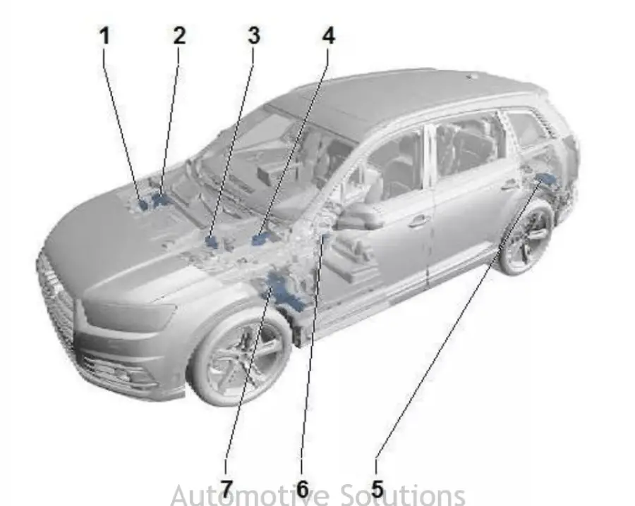
- Relay and Fuse Holder 1 -SR1-
- Wire distributor for bus terminal 30 – TV2- / wire distributor for bus terminal 30 – TV22-
- Wire Dispenser – TV1- /
- Main fuse holder on battery-A-
- Relay and Fuse Holder 3 -SR3-
- Fuse Holder C -SC
- Relay and Fuse Holder 2 -SR2-
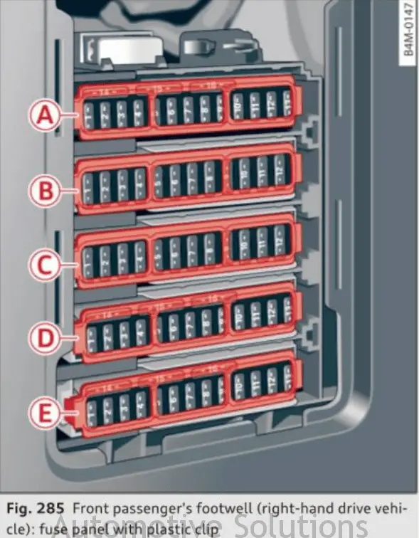
Audi Q7 Main Interior Fuse Diagram
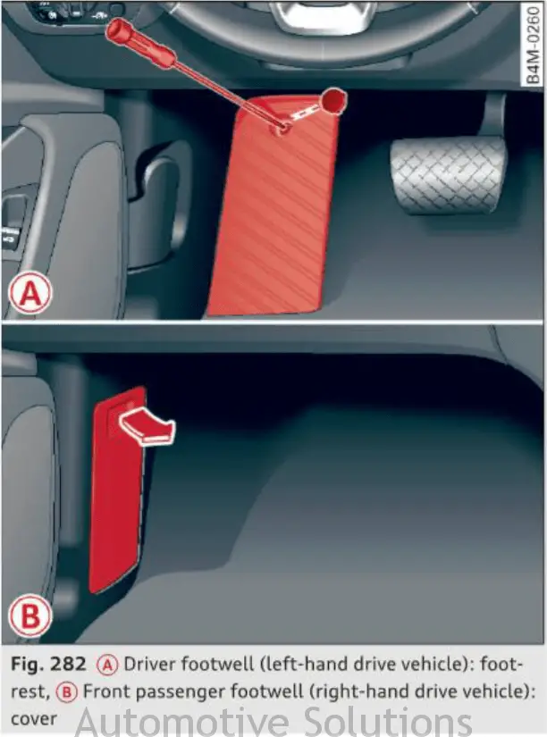
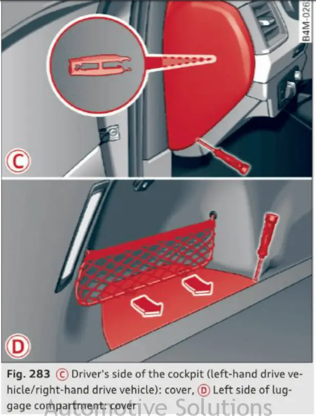
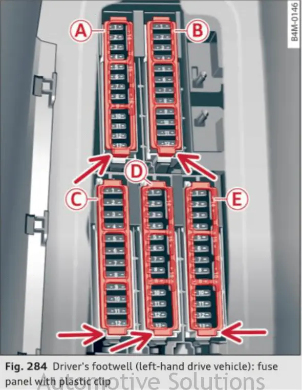
The fuses are located in t he foot well under the foot rest (left-hand drive vehicle) @ ¢ fig. 282 or behind the cove r (right-hand drive vehicle) @ . Additional fuses are located on the front side of the cockpit (driver’s side) © ¢ fig. 283 and under the left cover in the luggage compartment @ . .,. Switch the ignition and a ll electrical equipment off . .,. Check the following table to see which fuse be· longs to the equipment . .,. Remove the screwdriver and the reversible torx bit from the vehicle tool kit ¢ page 357 . .,. Remove the foot rest or the corresponding cover. .,. Remove the colored plastic clip from the fuse panel, if necessary ¢ page 365, fig. 284. You can dispose of the plastic clip . .,. Remove the clamp from the rear side of the cover @ . .,. Remove the fuse using the clamp . .,. Replace the blown fuse only with an identical new one . . Reattach the footrest or the cover.
Audi Q7 Relay Box (under hood)
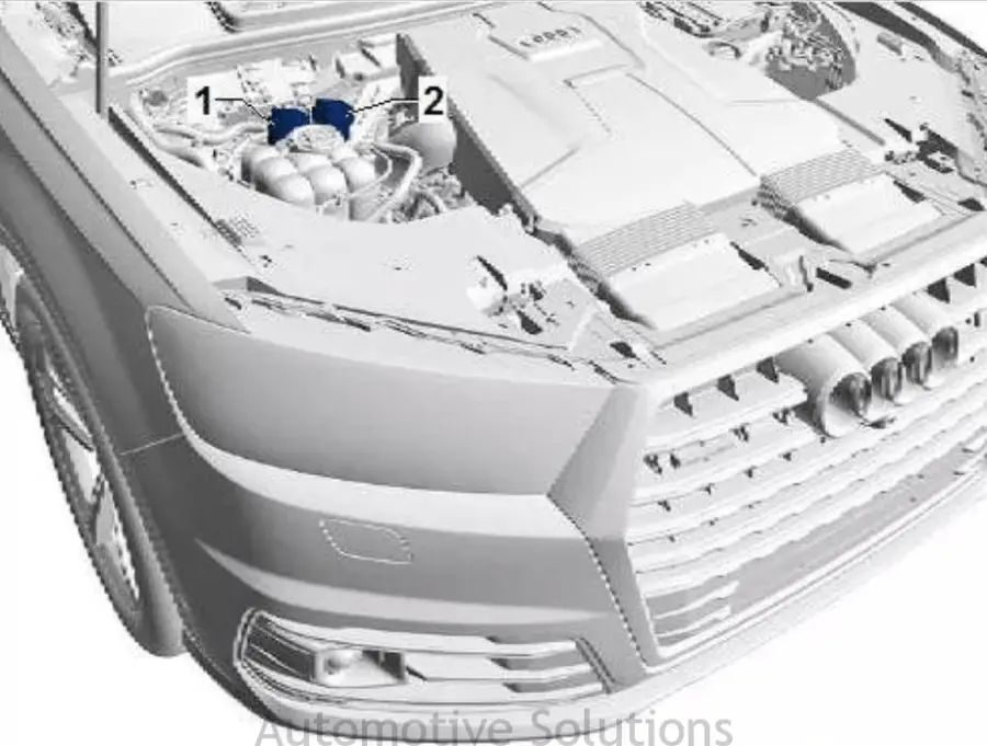
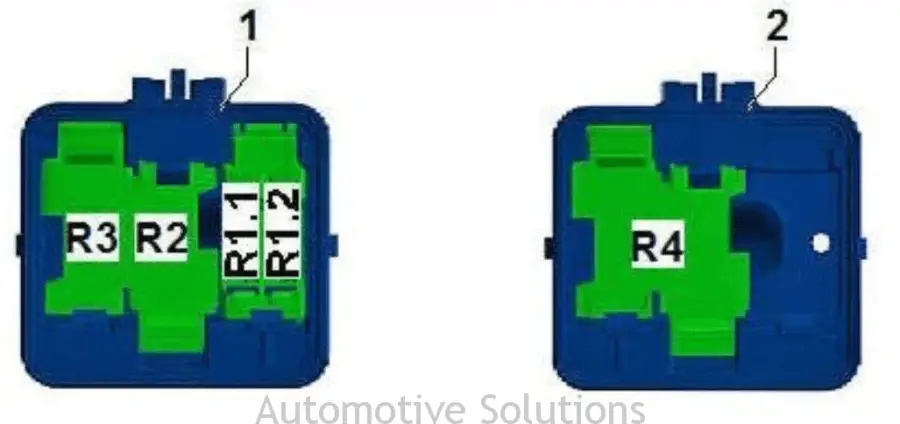
Mounting position, relay and fuse holder 1 -SR1-
1 – Relay and Fuse Holder 1 -SR1-, Part 1
2 – Relay and Fuse Holder 1 -SR1- , Part 2
Only on gasoline engine cars
R1.1 – not occupied
R1.2 – Fuse (50) -S216- , 5 A, to engine controller – J623-
3 SR2
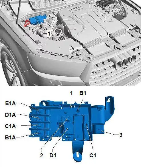
Audi Q7 Passenger floor wire junction under carpeting, main fuse holder on battery-A-
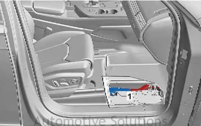
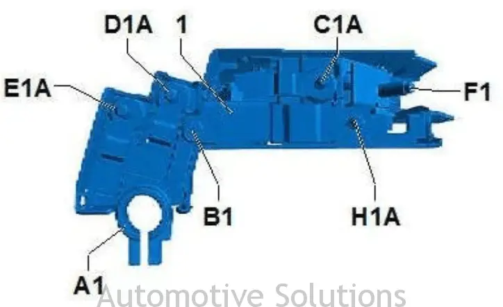
1 – Main fuse holder on battery-A-
A1 – Battery – A- Interface, Positive
B1 – Connection to the B299 Leading Lead 3 (30), Battery Monitoring Controller – J367-
C1A – Fusible Fuse 1 -S131- , 150 A
Car without high voltage system: to steering assist controller – J500-
Car with high voltage system: air-assisted heating controller – J604-
D1A – Fuse-Fuse 2 -S132- , 150 A
Cars without a high-voltage system: a positive connection to the leading lead of the B301 5 (30)
Car with high voltage system: positive connection 1 (30a) leading to the B315 leading cues
E1A – Fused fuse 3 -S133- , 200 A
Cars without a high-voltage system: a positive connection to the B300 leading lead 4 (30)
Cars without a high-voltage system: a positive connection to the B300 leading lead 4 (30) and access to the plus
Hot front windshield controller – J505-
F1 – Bus terminal 30 wire distributor – TV2-
H1A – Fused fuse 4 -S134- , 150 A
Car without high voltage system, leading to wire distributor – TV1-
Car with high voltage system, wire distributor to bus terminal 30 – TV28-
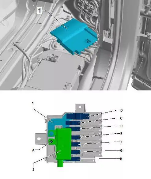
7 TV1
Audi Q7 Installation position, wire distributor – TV1-
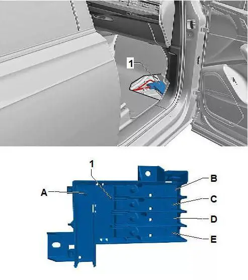
1 – Wire distributor – TV1-
A – Main fuse holder connector on battery -A-, blown fuse 4 -S134-
B – Fuse fuse 5 -S138- , 150 A, to air-assisted heating controller -J604-
C – Heatable front windshield fuse – S127- , 100 A, leading to a heated front windshield controller – J505-
D – blown fuse 6 -S139- , 80 A, to rear axle steering controller -J1019-
E – not occupied
8 connections
Audi Q7 Wire distributor for mounting position terminal 30 – TV2
Wire distributor of the installation position bus terminal 30 – TV2- / wire distributor 30 of the bus terminal 30 – TV22-
1 – Wire distributor for bus terminal 30 – TV2- / wire distributor for bus terminal 30 – TV22-
2 – Jumper Start Interface – TV32-
3 – Anti-interference capacitor – C24-
B1 – interface to the starter -B
Only on cars without a high voltage interface
B1 – Interface to starter generator – C29-
Only on cars with high voltage interface
C1 – not occupied
D1 – interface from F1, main fuse holder on battery -A-
B1A – glow plug fuse 2 -S189- , diesel engine model
Depending on engine type 60 A or 80 A
C1A – Secondary air pump fuse – S130- , 70 A, petrol engine model
C1A – glow plug fuse – S125- , diesel engine model
Depending on engine type 60 A, 80 A or 125 A
D1A – Radiator Fan 2nd Fuse – S104-
50 A or 70 A depending on equipment
E1A – Radiator Fan Single Fuse – S42-
50 A or 70 A depending on equipment
9 TV28
Audi Q7 Wire splitter 3 – TV28- at the installation position bus terminal 30
1 – Wire distributor 3 of bus terminal 30 – TV28-
2 – Protection Photocell -J201-
A – Main fuse holder connector on battery -A-, blown fuse 4 -S134-
B – Fuse 2 (30) -S205- , 250 A
Bus terminal 30, to the electric drive power and control electronics -JX1-
C – Fuse 3 (30) -S206- , 150 A
Bus terminal 30, to the steering assist controller – J500-
D – not occupied
E – Fuse 4 (30) -S207- , 80 A
Bus terminal 30, to the rear axle steering controller – J1019-
F – Fuse 5 (30) -S208- , 200 A
Bus terminal 30, leading to the positive connection 7 (30a) in the B321 leading thread
G – Fuse 6 (30) -S209- , 150 A
Bus terminal 30, leading to the positive connection 8 (30a) in the B322 leading thread
H – Fuse 7 (30) -S210- , 40 A
Bus terminal 30, leading to brake booster – NX6-
See Also: Audi Q7 – Recalls, Complaints, and Vehicle Specs.
