![]()
GUITAR EFFECTS PROCESSOR
GT-1000
Owner’s Manual
Provision of Bluetooth functionality
Please be aware that depending on the country in which you purchased the unit, Bluetooth functionality might not be included.
 Before using this unit, carefully read “USING THE UNIT SAFELY” and “IMPORTANT NOTES” (leaflet “USING THE UNIT SAFELY” and Owner’s Manual (p. 17)).After reading, keep the document(s) where it will be available for immediate reference.
© 2018 Roland Corporation

Owner’s Manual (this document)
Read this first. It explains the basic things you need to know in order to use the GT-1000.

PDF Manual (download from the Web)
• Parameter Guide
This explains all parameters of the GT-1000.
• Sound List
This is a list of the sounds built into the GT-1000.
• MIDI Implementation
This is detailed information about MIDI messages.
To obtain the PDF manual
1. Enter the following URL in your computer.
http://www.boss.info/manuals/
![]()
2. Choose “GT-1000” as the product name.
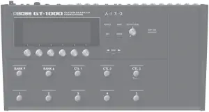
Getting Ready
Connecting the Equipment
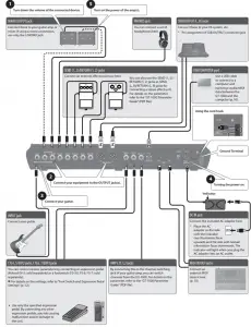
1 Turn down the volume of the connected device.
5 Turn on the power of the amp(s).
MAIN OUTPUT jack
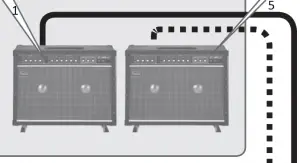 Connect these to your guitar amp or mixer. If using a mono connection, use only the L/MONO jack.
PHONES jack

You can connect a set of headphones here.
SUB OUTPUT (L, R) jacks
Connect these to your PA system, etc.
* Pin assignment of SUB OUTPUT connector/jack
SEND (1, 2)/RETURN (1, 2) jacks
Connect an external effect processor here.
 You can also use the SEND (1, 2)/ RETURN (1, 2) jacks as SEND (L, R)/RETURN (L, R) jacks for connecting a stereo effect unit. For details on the parameter, refer to the “GT-1000 Parameter Guide” (PDF file).
USB COMPUTER port
 Use a USB cable to connect to a computer and exchange audio/MIDI data between the GT-1000 and the computer (p. 10).
Using the cord hook
Ground Terminal
2 Connect your equipment to the OUTPUT jack(s).
3 Connect your guitar.
4 Turning the power on.
INPUT jack
Connect your guitar.

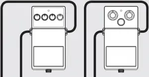
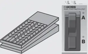
CTL4, 5/EXP2 jacks, CTL6, 7/EXP3 jacks
You can control various parameters by connecting an expression pedal (Roland EV-5: sold separately) or a footswitch (FS-5U, FS-6, FS-7: sold separately).
![]() For details on the settings, refer to “Foot Switch and Expression Pedal Settings” (p. 12).
For details on the settings, refer to “Foot Switch and Expression Pedal Settings” (p. 12).
 • Use only the specified expression pedal. By connecting any other expression pedals, you risk causing malfunction and/or damage to the unit.
AMP CTL 1,2 jacks
By connecting this to the channel switching jack of your guitar amp, you can switch channels from the GT-1000. For details on the parameter, refer to the “GT-1000 Parameter Guide” (PDF file).

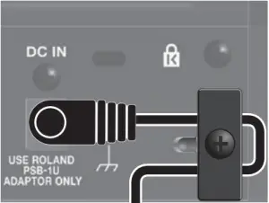
DC IN jack
Connect the included AC adaptor here.
* Place the AC adaptor so the side with the indicator (see illustration) faces upwards and the side with textual information faces downwards. The indicator will light when you plug the AC adaptor into an AC outlet.
MIDI IN/OUT jacks
Connect an external MIDI device here. (p. 10)
- To prevent malfunction and equipment failure, always turn down the volume, and turn off all the units before making any connections.
- Before turning the unit on/off, always be sure to turn the volume down. Even with the volume turned down, you might hear some sound when switching the unit on/off. However, this is normal and does not indicate a malfunction.
- To prevent the inadvertent disruption of power to your unit (should the plug be pulled out accidentally), and to avoid applying undue stress to the jack, anchor the power cord using the cord hook, as shown in the illustration.
2
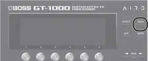
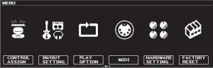
In this manual, the order of the MENU operations is written as follows.
<Example>
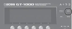
Press the [MENU] button.
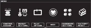
Use the [2] knob to select “IN/OUT SETTING.”
Use the [1] knob to select “INPUT.”
![]()
Choose [MENU] → “IN/OUT SETTING”→“INPUT.”
Turning the Power On
Turn the power on in the order of steps 1–5 .
To turn the power off, reverse the order.
Specify the Type of Amplifier You Have Connected
1. Choose [MENU] → “IN/OUT SETTING”→“MAIN OUT”→“OUTPUT SELECT.”
The menu screen appears.
2. Turn knob [1] to select the type of amp.
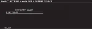
For details on the amp types, refer to the “GT-1000 Parameter Guide” (PDF file).
MEMO
In order to take full advantage of the GT-1000’s capabilities, we recommend that you connect to an input that is not affected by a preamp; for example, you should connect to a RETURN jack rather than to a guitar input jack which is affected by the preamp of your guitar amp.
Adjusting the Volume
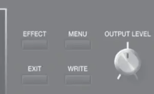
Use [OUTPUT LEVEL] knob to adjust the overall volume of the GT-1000.
Using the Tuner
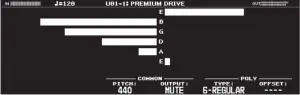
The GT-1000 is equipped with a conventional monophonic tuner which lets you tune your instrument one string at a time, and a polyphonic tuner which lets you play and tune all of your open strings simultaneously.
1. Press the [CTL3] (TUNER) switch.
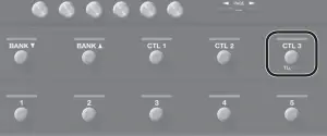
The tuner screen appears.
You can use the PAGE [![]() ][
][![]() ] buttons to switch the tuner display.
] buttons to switch the tuner display.
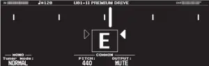
Monophonic/polyphonic display
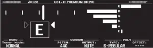
Monophonic display
Polyphonic display
You can also start the tuner as follows.
1. Choose [MENU] → “TUNER.”
“TUNER” is located in the second page of the menu. Use the PAGE [![]() ] [
] [![]() ] buttons to access the second page.
] buttons to access the second page.
Tuner Settings
To make tuner settings, use knobs [1]-[6] located below the display.
Tuner settings
| Parameter | Value | Explanation | |
| [1] | TUNER MODE | NORMAL, STREAM | Specifies the meter display method for the monophonic tuner. |
| [3] | Pitch | 435–445 Hz (default: 440 Hz) |
Specifies the reference pitch. |
| [4] | OUTPUT | MUTE | Sound will not be output while tuning. |
| BYPASS | While tuning, the sound of the guitar being input to the GT-1000 will be output without change. All effects will be off. | ||
| THRU | Allows you to tune while hearing the current effect sound.
* Only for monophonic tuner. |
||
| [5] | TYPE | 6-REGULAR, 6-DROP D, 7-REGULAR, 7-DROP A |
Selects the type of tuning for the polyphonic tuner. |
| [6] | OFFSET | -5–-1, —- | Adjusts the reference pitch of the polyphonic tuner in semitone units relative to standard tuning. |
3
Playing
Selecting a Patch
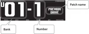
A combination of effects and their settings is called a “patch.”
Patch
User patch (U01-1-U50-5)
Can be overwritten
Preset patch (P01-1-P50-5)
Cannot be overwritten, however, you can write a Preset patch into the User area, modify the settings to your needs and store your modified version in the User area.
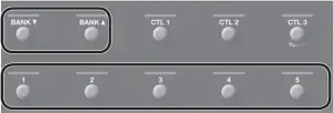
1. Use the [BANK![]()
 ] switches to select a bank.
2. Use the [1]-[5] switches to select a patch within the selected bank.
MEMO
You can also change patches by turning knob [1] below the display.
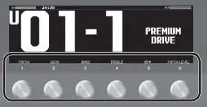
About the Play Screen
The screen that appears after you turn on the power is called the “Play screen.”
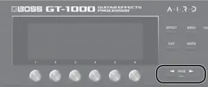
The following four types of play screen are provided; use the PAGE [![]() ] [
] [![]() ] buttons to switch between the types of display.
] buttons to switch between the types of display.
Large patch number

Large patch name

Show functions assigned to main unit and external switches
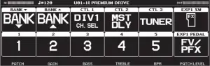
Show effect configuration
Icons shown in the play screen
![]()
| Indication | Explanation |
 |
Indicates the input level. |
 |
Indicates the output level. |
 |
Indicates the return level. |
 |
Indicates the send level. |
 |
Indicates the amount of compression when the compressor is operating. |
 |
Indicates that the editor is connected wirelessly. * Please be aware that depending on the country in which you purchased the unit, Bluetooth functionality might not be included. |
 |
Indicates the BPM. |
 |
Blinks in time with the BPM. |
 |
Indicates the page to which you navigate using the PAGE [ |
When the play screen is shown, you can turn knobs [1]-[6] to adjust the parameters that are shown above each knob.
MEMO
You can change the parameters that are adjusted by knobs [1]-[6] when the play screen is shown.
For details, refer to the “Assigning Favorite Parameters to [1]-[6] Knobs” (p. 8).
4
Editing: Effects
Basic Procedure for Effect Editing
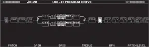
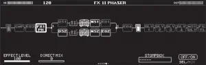
The edit screens show the block configuration (effect chain) of all effects provided by the GT-1000, as well as the output and send/ return. You can edit from this effect chain display by selecting the block that you want to edit.
1. Press the [EFFECT] button.
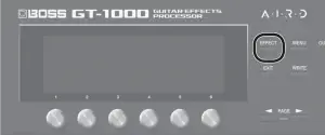
The edit screen (effect chain) appears.
2. Turn knob [6] to select the block that you want to edit.
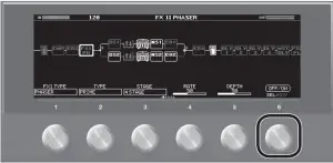
The selected block is enclosed by a thick frame.

* By pressing knob [6] you can turn the selected effect on/off. Effects that are off are shown in gray. When the effect is turned on, it is shown in white.

3. Use knobs [1]-[5] to adjust the parameters that are shown below the screen.
Use the PAGE [![]() ][
][![]() ] buttons to switch between the parameters that you want to edit. The current page is indicated in the lower center of the screen.
] buttons to switch between the parameters that you want to edit. The current page is indicated in the lower center of the screen.
* To change a value in larger steps, turn a knob while pressing it.
* The number of parameters and pages differs depending on the
effect.
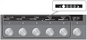
Editing while viewing all parameters
From the edit screen, you can long-press knob [6] to see a list of all parameters of the selected block. You can edit the parameters from this list.
1. Turn knobs [1]-[6] to edit the value of the parameters shown in the screen.
Use the PAGE [![]() ][
][![]() ] buttons to switch between lists of parameters.
] buttons to switch between lists of parameters.
Effect Placement
By moving blocks such as effects, output, and send/return, you can freely change the order in which the effects are placed, or arrange them in parallel.
Changing the placement of effects etc.
1. Press the [EFFECT] button.
The effect chain is shown.
2. Use knob [6] to select the block that you want to move.
3. While pressing knob [6], turn it left or right.
The selected block moves left or right.
5
Switching patches without interrupting the sound
The GT-1000 is equipped with a new type of high-speed patch switching system, allowing you to switch patches with minimal interruption of the sound. The fastest possible switching is automatically performed for each patch, and switching without interrupting the sound is also possible.
Tips for preventing interruptions in the sound
To prevent interruptions in the sound, observe the following points when you create the patches that are used before and after the switch.
• Avoid changing the position of blocks within the chain.
• Use multiple blocks when placing the effects (don’t change the TYPE within the same block).
• Use parallel positioning, and switch the channel.
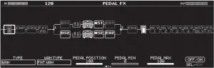
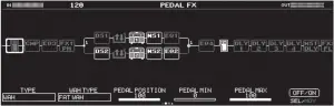
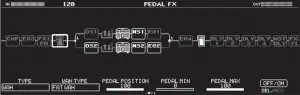
Example:
Switching from a clean sound that uses chorus and deep delay, to a crunch sound that uses phaser and shallow delay.
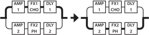
The same chain is used for both patches, both before and after switching. The settings of the effect used before switching are placed in parallel with the settings used after switching.
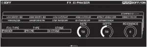
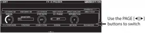
Using STOMPBOX
Your preferred settings for each effect can be saved as a “STOMPBOX.” You can select these saved settings and use them to create your sound just as though you were connecting compact pedal effects. The STOMPBOX data is common to all patches; this means that all patches using the same STOMPBOX can be edited simultaneously.
1. Press the [EFFECT] button.
2. Use the [6] knob to choose the effect you’re going to edit.
3. Use the PAGE [![]() ] [
] [![]() ] buttons to move to the last page.
] buttons to move to the last page.
4. Press the [5] knob.
The STOMPBOX select window appears.
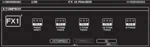
5. Turn knob [5] to select the STOMPBOX type.
6. Press the [5] knob.
Editing the STOMPBOX
1. Turn knobs [1]-[5] to edit the parameter value that are shown in the screen.
Use the PAGE [![]() ] [
] [![]() ] buttons to switch between lists of parameters.
] buttons to switch between lists of parameters.
* Any changes you make by editing will disappear when you switch patches. Save your changes if necessary.
Reading STOMPBOX Settings into a Patch
1. Press the [EFFECT] button.
2. Use the [6] knob to choose the effect you’re going to edit.
3. Use the PAGE [![]() ] [
] [![]() ] buttons to move to the last page.
] buttons to move to the last page.
4. Press the [5] knob.
The STOMPBOX select window appears.
5. Turn knob [5] to select the STOMPBOX type.
6. Press the [4] knob.
The contents of the STOMPBOX are recalled into the patch. You can edit the patch without modifying the contents of the STOMPBOX.
Writing Patch Settings into a STOMPBOX
1. Press the [EFFECT] button.
2. Use the [6] knob to choose the effect you’re going to save.
3. Use the PAGE [![]() ] [
] [![]() ] buttons to move to the last page.
] buttons to move to the last page.
4. Press the [5] knob.
The STOMPBOX select window appears.
5. Press the [3] knob.
6. Turn knob [1] to select the writing-destination STOMPBOX.
7. Use knobs [3]-[6] to name the STOMPBOX.
Reference
For details on naming the STOMPBOX, refer to “Editing a name” (p. 7).
6
Saving a Patch
When you want to save a patch you have created, save it as a user patch by following the procedure below. If you do not save the patch, the edited settings will be lost when you turn off the power or switch to another patch.
1. Press the [WRITE] button.

2. Press knob [1] to select “WRITE” (PATCH WRITE).

3. Use knob [1] to select the save-destination (U01-1-U50-5).
You can use knobs [3]-[6] to edit the name.
Editing a name
To edit the patch name, use knob [6] to move the cursor and use knob [5] to change the character.
| Controller | Operation |
| Turn the [3] knob | Selects the type of characters |
| Press the [3] knob | Delete one character (delete) |
| Turn the [4] knob | Switch uppercase/lowercase |
| Press the [4] knob | Insert one space (insert) |
| Turn the [5] knob | Changes the character |
| Turn the [6] knob | Moves the cursor |
4. Press the [WRITE] button once again.
The patch is written.
7
Editing: MENU
Basic MENU Operations
Here you can make settings that are common to the entire GT-1000 (system parameters).
For details on the parameter, refer to the “GT-1000 Parameter Guide” (PDF file).
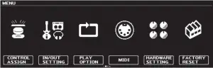
1. Press the [MENU] button.
* You can use the PAGE [![]() ][
][![]() ] buttons to see additional items.
] buttons to see additional items.
2. Press a knob [1]-[6] to select the item that you want to edit.
A sub-menu appears.
3. Once again press a knob [1]-[6] to select the item that you want to edit.
4. Use knobs [1]-[6] to select parameters or edit the values.
* The method of selecting parameters or editing values differs depending on the item. For details, refer to “GT-1000 Parameter Guide” (PDF).
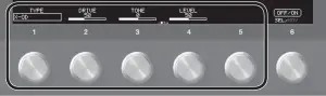
Assigning Favorite Parameters to [1]-[6] Knobs
Here’s how to assign the parameters that are controlled by knobs [1] [6] when the play screen (p. 4) is shown.
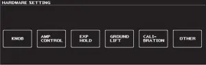
1. Choose [MENU] →“HARDWARE SETTING”→“KNOB.”
2. Use the [1]-[6] knobs to specify the parameters to be controlled by each knob.
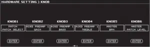
3. Press the [EXIT] button a number of times to return to the play screen.
Adjusting the Contrast (Brightness) of the Display
You can adjust the brightness of the display.
1. Choose [MENU]→“HARDWARE SETTING”→“OTHER.”
2. Adjust the value with the [2] knob.
Restoring the Factory Default Settings (Factory Reset)
Restoring the GT-1000’s settings to their original factory default settings is referred to as “Factory Reset.”
Not only can you return all of the settings to the values in effect when the GT-1000 was shipped from the factory, you can also specify the items to be reset.
* When you execute “Factory Reset,” the settings you made will be lost. Save the data you need to your computer using the dedicated software.
1. Choose [MENU]→ “FACTORY RESET.”
2. Choose the type of settings to be restored to the factory default settings with knobs [1] and [6].
| Knob | Parameter | Value | Explanation |
| [1]
[6] |
FROM
TO |
SYSTEM | System parameter settings |
| U01-1– U50-5 | Settings for Patch Numbers U01-1–U50-5 | ||
| STOMPBOX | Settomgs for STOMPBOX |
3. Press the [WRITE] button.
Press the [6] button to execute the factory reset.
To cancel factory reset, press the [5] button.
Once the Factory Reset is complete, you are returned to the Play screen.
8
Turning Off the Auto Off Function
The GT-1000 can turn off its power automatically. The power will turn off automatically when 10 hours have passed since you last played or operated the unit. The display will show a message approximately 15 minutes before the power turns off.
With the factory settings, this function is turned “ON” (power-off in 10 hours). If you want to have the power remain on all the time, turn it “OFF.”
1. Choose [MENU]→ “HARDWARE SETTING”→“OTHER.”
2. Use the [1] knob to select “OFF.”
3. Press the [EXIT] button a number of times to return to the play screen.
Using the Metronome
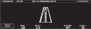
1. Choose [MENU]→“METRONOME.”
“METRONOME” is located in the second page of the menu. Use the PAGE [![]() ][
][![]() ] buttons to access the second page.
] buttons to access the second page.
Metronome display
Metronome settings
Use knobs [1]-[6] below the display to make metronome settings.
| Parameter | Value | Explanation | |
| [1] | EFFECT TEMPO | — | By pressing knob [1] you can set the metronome’s BPM to the master BPM value. |
| [2] | BPM | 20–250 | Specifies the tempo. |
| [3] | BEAT | 1/1–8/1, 1/2–8/2, 1/4–8/4, 1/8–8/8 | Specifies the time signature. |
| [5] | OFF/ON | OFF, ON | Turns the metronome on/off. |
| [6] | LEVEL | 0–100 | Specifies the volume of the metronome. |
9
Connecting to a Computer
By connecting the GT-1000 to a computer via USB, you can do the following.

• Transmit and receive digital audio signals between the computer and the GT-1000
• Edit and manage patches, and display the “GT-1000 Parameter Guide” (PDF file) on a computer using the dedicated software
• Download patches from our dedicated BOSS TONE CENTRAL website
![]() http://bosstonecentral.com/
http://bosstonecentral.com/
Installing the USB Driver
You must install the USB driver before connecting to a computer.
Please download the USB driver from the website shown below. Install this special driver before making a USB connection. For further details, refer to the Readme.htm file that comes with the download.
![]() http://www.boss.info/support/
http://www.boss.info/support/
The program you need to use, and the steps you need to take to install the USB driver will differ depending on your computer setup, so please carefully read and refer to the Readme.htm file that comes with the download.
Using the GT-1000 as an Audio Interface
You can record the sound of the GT-1000 on your computer, or have sound from your computer be output from the OUTPUT jacks.
* For details of the audio signal flow when connected via USB and instructions on how to make settings, refer to “GT-1000 Parameter Guide” (PDF file).
* Refer to the instruction manual for the software you are using to learn how to switch the input source of the software.
Making use of the GT-1000’s dedicated software
You can easily download dedicated software from our BOSS TONE CENTRAL website. For details on how to use the software, refer to the Readme.htm file that comes with the download.
![]() http://bosstonecentral.com/
http://bosstonecentral.com/
Using the dedicated software allows you to do the following:
• Easily download patches from our BOSS TONE CENTRAL website.
• Edit patch settings
• Name patches
• Organize patches in order and switch them around
• Back up patches and system settings, and return to the backed up settings
• Display the “GT-1000 Parameter Guide” (PDF file) on your computer
Connecting the GT-1000 with an External MIDI Device
On the GT-1000, you can use MIDI to perform the following operations.
Operations from the GT-1000
| Operation | Explanation |
| Transmit program change messages | When you select a patch on the GT-1000, the program change message specified by PATCH MIDI is also transmitted. The external MIDI device that receives this program change message will switch to the corresponding settings. |
| Transmit control change messages | Operations of a [CTL1]–[CTL3] switches, or footswitches or expression pedals connected to the CTL 4, 5/EXP2, and CTL 5, 6/EXP3 jacks, are transmitted as control change messages. These messages can control parameters on an external MIDI device. |
Operations from an External MIDI Device
| Operation | Explanation |
| Switch patch numbers | When the GT-1000 receives a program change message from an external MIDI device, the GT-1000 will change patches. |
| Receive control change messages | The GT-1000 can receive control change messages to control a specified parameter while you perform. |
| Receive data | The GT-1000 can receive data that is transmitted from another GT-1000 unit, or data that was saved on a MIDI sequencer. |
Connection example

Settings
1. Choose [MENU]→ “MIDI.”
2. Use [1]-[6] knobs to specify the value of each parameter.
For details on MIDI, refer to “GT-1000 Parameter Guide)” (PDF file).
10
Using the
Provision of Bluetooth functionality
Please be aware that depending on the country in which you purchased the unit, Bluetooth functionality might not be included.
Here’s What You Can Do
Bluetooth functionality creates a wireless connection between a mobile device such as a smartphone or tablet (subsequently referred to as the “mobile device”) and this unit, allowing you to do the following.
• You can use the BOSS TONE STUDIO app to edit the sound or edit the sound library.
For details on BOSS TONE STUDIO, refer to the Boss website.
https://www.boss.info/
Connecting to an App
The following steps are one possible example. For details, refer to the owner’s manual of your mobile device.
1. Power-on the GT-1000 unit and the mobile device.
2. In your mobile device’s settings, turn Bluetooth on.

NOTE
Even if the “Available devices” list shows “GT-1000,” don’t tap it.
3. Start the “BOSS TONE STUDIO for GT-1000” app that you installed in your mobile device.
4. Tap [Bluetooth MIDI DEVICE] that appears in the screen, and then tap “GT-1000.”
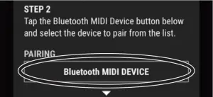
* If you changed the Bluetooth ID (p. 11), the changed number is shown following “GT-1000.”
Verify that “*” is shown at the upper right of GT-1000.
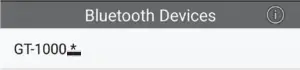
* If “GT-1000” is not shown, tap “SCAN” at the very bottom of the Bluetooth Devices screen, and search again.
5. Tap the Android back button to return to the previous screen.
6. Verify that “GT-1000” is shown for “CONNECT.”
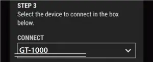
7. Tap [OK] to start communication.
If you have multiple GT-1000 units
If you set the Bluetooth ID parameter to something other than “OFF,” a number is added following the device name of the GT-1000. This lets you distinguish multiple GT-1000 units.
1. Choose [MENU]→ “HARDWARE SETTING”→“OTHER.”
2. Turn knob [6] to specify the ID.
| Value | Example | |
| OFF, 1–9 | OFF (default) | “GT-1000” |
| 1 | “GT-1000 1” | |
11
Foot Switch and Expression Pedal Settings
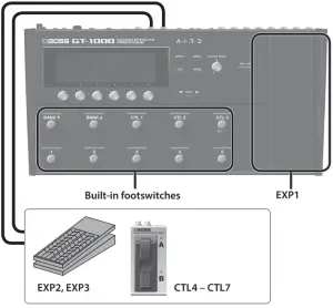
A variety of functions can be assigned each of the top panel footswitches, the expression pedal (EXP1), and expression pedals or footswitches that are connected to the rear panel CTL4, 5/EXP2 jack and CTL6, 7/EXP3 jack (p. 14).
Assigning a Function
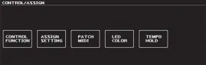
1. Choose [MENU]→ “CONTROL ASSIGN”→“CONTROL FUNCTION.”
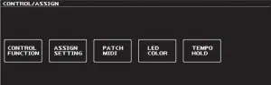
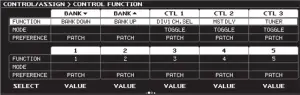
2. Turn knob [1] to select the item that you want to set.
Turning the knob will move the selected item vertically.
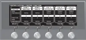
The settings of the selected item can now be edited.
3. Turn knobs [2]-[6] to edit the value of the item selected for each switch.
* The foot switch and expression pedal functions must be specified for each patch; however, if you set PREFERENCE to SYSTEM, all patches will use those functions in common.
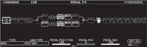
Making Assignments from the Effect Edit Screen (Quick Assign)
In the effect edit screen (p. 5), you can select an effect parameter and assign that parameter to the switch of your choice.
1. Press the [EFFECT] button.
2. Turn knob [6] to select the block that you want to edit.
3. Long-press the knob [1]-[5] for the parameter that you want to assign.
The assign matrix setting screen appears.
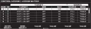
* You can also access the assign matrix setting screen in the same way from the all-parameter list screen (p. 5). You can also access it by selecting [MENU]→ “CONTROL ASSIGN”→“ASSIGN SETTING.”
4. Press knob [1] to turn the SW on.
5. Turn knobs [2]-[6] to edit parameters.
If necessary, use the PAGE [![]() ][
][![]() ] buttons to switch between pages of settings.
] buttons to switch between pages of settings.
Use SOURCE to specify the pedal or MIDI message that you will operate.
12
Adjusting the Expression Pedal (Pedal Calibration)
Although the GT-1000’s expression pedal has been set for optimum operation at the factory, extended use and the operating environment can result in the pedal going out of adjustment.
If you encounter problems such as being unable to fully cut off the sound with the volume pedal or being unable to switch the PEDAL FX, you can use the following procedure to readjust the pedal.
1. Choose [MENU]→ “HARDWARE SETTING”→“CALIBRATION.”
The PEDAL CALIBRATION screen appears.

2. Press the heel end of the pedal, and press the [WRITE] button.
The screen will indicate “OK,” and then a screen like the following will appear.

3. Press the toe end of the pedal, and press the [WRITE] button.
The screen will indicate “OK,” and then a screen like the following will appear.
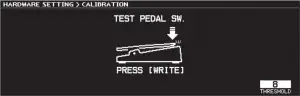
4. Strongly press the toe end of the pedal.
Verify that the PEDAL FX indicator lights when you strongly press the toe end.
* If you want to change the lighting sensitivity of the PEDAL FX indicator, repeat step 4 while you adjust the THRESHOLD value with knob [6].
5. Press the [WRITE] button.
The screen will indicate “COMPLETED!”

* When you operate the expression pedal, please be careful not to get your fingers pinched between the movable part and the panel. In places where small children are present, make sure that an adult provides supervision and guidance.
13
Connecting External Pedals
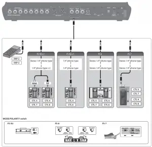
14
Looper
You can record up to 38 seconds (MONO) of a performance and play back the recorded section over and over. You can also layer additional performances with the recording as it plays back (overdubbing). This lets you create real-time backing performances on the fly.
Assigning Looper Functions to Switches
To use the looper, you must first assign the looper’s record, play, and overdub functions to the desired switches. Here we explain an example of how you can use the [CTL1]-[CTL3] switches of the GT1000 to operate the looper.
1. Select the patch with which you want to use the looper.
2. Choose [MENU]→“CONTROL ASSIGN”→“CONTROL FUNCTION.”
3. For “CTL 1″-”CTL 3,” set FUNCTION as follows.
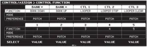
| Parameter | Value | Explanation |
| CTL 1 | LOOPER | Starts recording. Each time you press the switch, operation alternates between playback and overdubbing. |
| CTL 2 | LOOPER STOP | Stops recording or playback. |
| CTL 3 | LOOPER CLEAR | Clears the recording. |
MEMO
• With the factory settings, preset patches P50-1P50-5 and user patches U50-1-U50-5 are set as shown above.
• You can also stop and clear using only the [CTL1] switch that is assigned to LOOPER. Press the switch twice to stop. Hold down the switch for two seconds or longer to clear the phrase.
Record
Recording will start immediately when you press the switch. At the point where you want to loop, press the pedal to switch to playback.
 ⇓
⇓
Loop Playback
Play back the loop.
Pressing the switch will switch to overdubbing.
⇓⇑
Overdub
Record additional layers while playing back the loop.
Press the switch to switch to playback.
⇓
Stop/Clear
To stop, press the switch to which STOP is assigned.
To clear the phrase, press the switch to which CLEAR is assigned.
Loop Playback Level Setting
If you set the playback level at 100 (default value), the volume of the performance and that of the loop playback will be identical.
If you set the playback level to a value lower than 100, the volume of the playback will be lower than that of the performance. As a result, the sound of the performance won’t get buried by the loop playback sound, even if you record a multiple number of times.
1. Press the [EFFECT] button.
2. Turn knob [6] to select LOOPER.

3. Turn knob [1] to specify the “PLAY LEVEL” value.
Switch Color
| Color | Status |
| Red | Record |
| Orange | Overdub |
| Green | Playback |
| Green (blink) | Stopped (phrase exists) |
| Blue | Stopped (no phrase) |
MEMO
• The recording time is up to 38 seconds (MONO). In stereo mode, the recording time is up to 19 seconds.
• The recorded content will be lost when you turn off the Looper or turn off the power.
15
Main Specifications
BOSS GT-1000: Guitar Effects Processor
| Sampling Frequency | 96 kHz |
| AD Conversion | 32 bits + AF method
AF method (Adaptive Focus method) This is a proprietary method from Roland & BOSS that vastly improves the signal-tonoise (SN) ratio of the AD and DA converters. |
| DA Conversion | 32 bits |
| Patches | 250 (User) + 250 (Preset) |
| Phrase Loop | 38 sec. (MONO) 19 sec. (STEREO) |
| Nominal Input Level | INPUT: -10 dBu |
| RETURN1: -10 dBu | |
| RETURN1: -10 dBu | |
| Maximum Input Level | INPUT: +18 dBu |
| RETURN1: +8 dBu | |
| RETURN1: +8 dBu | |
| Input Impedance | INPUT: 1 M Ω |
| RETURN1: 1 M Ω | |
| RETURN2: 1 M Ω | |
| Nominal Output Level | MAIN OUTPUT (L/MONO, R): -10 dBu |
| SUB OUTPUT (L, R): +4 dBu | |
| PHONES: -10 dBu | |
| SEND1: -10 dBu | |
| SEND2: -10 dBu | |
| Output Impedance | MAIN OUTPUT (L/MONO, R): 1 k Ω |
| SUB OUTPUT (L, R): 600 Ω | |
| PHONES: 20 Ω | |
| SEND1: 1 k Ω | |
| SEND2: 1 k Ω | |
| Recommended Load Impedance | MAIN OUTPUT (L/MONO, R): 10 k Ω or greater |
| SUB OUTPUT (L, R): 600 Ω or greater | |
| PHONES: 44 Ω or greater | |
| SEND1: 10 k Ω or greater | |
| SEND2: 10 k Ω or greater | |
| Display | Graphic LCD (512 x 160 dots, backlit LCD) |
| Connectors | INPUT jack: 1/4-inch phone type |
| MAIN OUTPUT (L/MONO, R) jacks, SEND1 jack, RETURN1 jack, SEND2 jack, RETURN2 jack: 1/4-inch phone type | |
| SUB OUTPUT (L, R) connectors: XLR type | |
| PHONES jack: Stereo 1/4-inch phone type | |
| CTL4, 5/EXP2 jack, CTL6, 7/EXP3 jack, AMP CTL1, 2 jack: 1/4- inch TRS phone type | |
USB COMPUTER  port: USB type B port: USB type B |
|
| DC IN jack | |
| MIDI (IN, OUT) connectors | |
| Power Supply | AC adaptor |
| Current Draw | 1.2 A |
| Dimensions | 462 (W) x 248 (D) x 70 (H) mm
18-3/16 (W) x 9-13/16 (D) x 2-13/16 (H) inches Maximum height: 462 (W) x 248 (D) x 95 (H) mm 18-3/16 (W) x 9-13/16 (D) x 3-3/4 (H) inches |
| Weight | 3.6 kg
7 lbs 15 oz |
| Accessories | AC adaptor, Owner’s Manual, Leaflet “USING THE UNIT SAFELY” |
| Options (sold separately) | Footswitch: FS-5U, FS-5L, FS-6, FS-7, Expression Pedal: EV-30, FV-500L/500H, Roland EV-5 |
* 0 dBu = 0.775 Vrm
* This document explains the specifications of the product at the time that the document was issued. For the latest information, refer to the Roland website.
16
USING THE UNIT SAFELY
Concerning the Auto Off function
The power to this unit will be turned off automatically after a predetermined amount of time has passed since it was last used for playing music, or its buttons or controls were operated (Auto Off function). If you do not want the power to be turned off automatically, disengage the Auto Off function (p. 9).
Use only the supplied AC adaptor and the correct voltage
 Be sure to use only the AC adaptor supplied with the unit. Also, make sure the line voltage at the installation matches the input voltage specified on the AC adaptor’s body. Other AC adaptors may use a different polarity, or be designed for a different voltage, so their use could result in damage, malfunction, or electric shock.
Use only the supplied power cord
Use only the attached power cord. Also, the supplied power cord must not be used with any other device.
CAUTION
Take care so as not to get fingers pinched
 When handling the following moving parts, take care so as not to get fingers, toes, etc., pinched. Whenever a child uses the unit, an adult should be on hand to provide supervision and guidance.
• Expression pedal (p. 12)
Handle the ground terminal carefully
If you remove the screw from the ground terminal, be sure to replace it; don’t leave it lying around where it could accidentally be swallowed by small children. When refastening the screw, make that it is firmly fastened, so it won’t come loose.
IMPORTANT NOTES
Placement
• Depending on the material and temperature of the surface on which you place the unit, its rubber feet may discolor or mar the surface.
Repairs and Data
• Before sending the unit away for repairs, be sure to make a backup of the data stored within it; or you may prefer to write down the needed information. Although we will do our utmost to preserve the data stored in your unit when we carry out repairs, in some cases, such as when the memory section is physically damaged, restoration of the stored content may be impossible. Roland assumes no liability concerning the restoration of any stored content that has been lost.
About the Ground Terminal
• If you are using the ground terminal, connect it with an external ground. When the unit is grounded, a slight hum may occur, depending on the particulars of your installation. If you are unsure of the connection method, contact the nearest Roland Service Center, or an authorized Roland distributor, as listed on the “Information” page.
- Unsuitable places for connection
• Water pipes (may result in shock or electrocution)
• Gas pipes (may result in fire or explosion)
• Telephone-line ground or lightning rod (may be dangerous in the event of lightning)
Additional Precautions
• Any data stored within the unit can be lost as the result of equipment failure, incorrect operation, etc. To protect yourself against the irretrievable loss of data, try to make a habit of creating regular backups of the data you’ve stored in the unit.
• Roland assumes no liability concerning the restoration of any stored content that has been lost.
• Never strike or apply strong pressure to the display.
• Use only the specified expression pedal. By connecting any other expression pedals, you risk causing malfunction and/or damage to the unit.
Caution Regarding Radio Frequency Emissions
- The following actions may subject you to penalty of law.
• Disassembling or modifying this device.
• Removing the certification label affixed to the back of this device.
Intellectual Property Right
• It is forbidden by law to make an audio recording, video recording, copy or revision of a third party’s copyrighted work (musical work, video work, broadcast, live performance, or other work), whether in whole or in part, and distribute, sell, lease, perform or broadcast it without the permission of the copyright owner.
• Do not use this product for purposes that could infringe on a copyright held by a third party. We assume no responsibility whatsoever with regard to any infringements of third-party copyrights arising through your use of this product.
• Roland and BOSS are either registered trademarks or trademarks of Roland Corporation in the United States and/or other countries.
• ASIO is a trademark and software of Steinberg Media Technologies GmbH.
• This product contains eParts integrated software platform of eSOL Co.,Ltd. eParts is a trademark of eSOL Co., Ltd. in Japan.
• The Bluetooth® word mark and logos are registered trademarks owned by Bluetooth SIG, Inc. and any use of such marks by Roland is under license.
• This Product uses the Source Code of T-Kernel under T-License 2.0 granted by the T-Engine Forum (www.tron.org).
• Company names and product names appearing in this document are registered trademarks or trademarks of their respective owners.
17
![]()