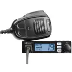
19 DX IV / 19 ULTRA IV Series
CB Radio Transceiver![]()
Owner’s Manual
Nothing Coomes Chose to a Cobera
Introduction
![]() Our Thanks, The CB Story, and Customer Assistance
Our Thanks, The CB Story, and Customer Assistance
Thank you for purchasing the Cobra 19 Series CB Radio Transceiver. Properly used, this Cobra product will give you many years of reliable service.
The Citizens Band Story
The Citizens Band lies between the shortwave broadcast and 10-meter amateur radio bands and was established by law in 1949. The Class D two-way communications service was opened in 1959. (CB also includes a Class A citizens band and Class C remote control frequencies.)
Product Features
Product Features
Features
- 40 CB Radio Channels
- Instant Channels 9/19 NOR
- PA System
- Compact Size
- Dynamic Microphone
- Nine Foot Microphone Cord
- Front Panel Microphone Connector
- RF Gain
![]()
FCC Regulations
![]() FCC Compliance
FCC Compliance
Any changes or modifications not expressly approved by Cobra Electronics could void your authority to operate the equipment.
This device complies with Part 15 of the FCC rules. Operation is subject to the following two conditions:
(1) This device may not cause harmful interference, and (2) this device must accept any interference received, including interference that may cause undesired operation.
You should find all of the following items in this package:
Installation and Start-Up
Secondary Icons Select a location for the transceiver and microphone bracket that is convenient for operation. In automobiles, the transceiver is usually mounted to the underneath of the dash panel, with the microphone bracket beside it. ![]()
A universal mounting bracket is supplied along with self-tapping screws and star washers. The transceiver is held in the universal mounting bracket by two thumbscrews, permitting adjustment at the most convenient angle.
To mount and connect your transceiver:
![]()
- Hold the radio with the mounting bracket in the exact location desired. Remove the mounting bracket and use it as a template to mark the location for
the mounting screws. - Drill necessary holes and secure mounting bracket in location.
- Connect the antenna cable plug to the re cep ta cle marked “ANT” on the back of the unit.
- Connect the red lead of the DC power cord to an accessory 12-volt fuse.
- Connecting the black lead to the negative side of the automobile. This is usually the chassis. Any convenient location with good electrical contact (remove paint) may be used.
NOTE
Before installing the CB radio, visually check the vehicle battery connections to determine which battery terminal, positive or negative (positive is the larger of the two) is grounded to the engine block (or chassis). - Mount the microphone bracket on the right side of the transceiver or near it using two screws supplied. When mounting in an automobile, place the bracket under the dash so the microphone is readily accessible.
- Attach the four-pin microphone cable to the receptacle on the front of the unit and install the unit in bracket securely.
NOTE
For improved CB radio performance, connect the radio power leads directly to the vehicle battery. This helps to ensure the following: 1) reduces conducted power line noise into radio by taking advantage of the mechanical altering properties of the vehicle battery.
2) Using the correct wire gauge between the battery and radio, helps to minimize Voltage drop to the radio transmitter section to maximize transmitter RF output power.
Operating Your Mobile Radio
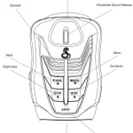
![]() Antenna Connector
Antenna Connector
This female Connector on the rear panel permits the connection of the transmission line cable male connector to the transceiver.![]() External Speaker
External Speaker
The external speaker jack on the rear panel is used for an External Speaker. The external speaker should have an 8-ohm impedance and be rated to handle at least 4.0 watts. When the external speaker is plugged in, the internal speaker is automatically disconnected.
![]() NOTE
NOTE
Cobra external speakers are rated 15 watts.
![]() Public Address (PA)
Public Address (PA)
An external PA speaker may be connected to the PA speaker jack when used as a public address system. The speaker should be directed away from the microphone to prevent acoustic feedback. Physical separation or isolation of the microphone and speaker must be employed when operating the PA at high output levels.
![]() Power
Power
These wires supply Power to the CB radio.
This cable is permanently attached to the radio.
If you wish to remove the radio after installation, disconnects at fuse holder and ground connector.
Operating Your Mobile Radio
![]() Turning on Your Mobile Radio
Turning on Your Mobile Radio
Turn the On-Off/Volume knob clockwise to turn the power on and set the desired listening volume.
CB Antenna
Only a properly matched antenna system will allow maximum power output. In mobile installations (cars, trucks, boats, etc.), a system that is nondirectional should be used. When installed in a boat, the transceiver will not operate at maximum efficiency without a ground plate unless the vessel has a steel hull. Before installing the transceiver in a boat, consult your dealer for information regarding an adequate grounding system.
![]() NOTE
NOTE
Cobra offers a line of antennas for use with your 19 Series CB Radio.
Consult your Cobra dealer or go to Cobra.com for antenna options.
![]() Microphone Connector
Microphone Connector
Allows for convenient removal of the Microphone plug when storage is required. The Microphone MUST be connected to the unit at all times, when in use, for proper operation.
Operating Your Mobile Radio
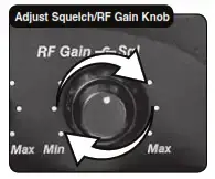
Squelch
This control is used to cut off or eliminate receiver background noise in the absence of an incoming signal. Adjust until the receiver noise disappears. This will require the incoming signal to be slightly stronger than the average receiver noise. Further clockwise rotation will increase the threshold level which a signal must overcome in order to be heard. Only strong signals will be heard at a maximum clockwise setting. Squelch is the “control gate” for incoming signals.
![]() To squelch your radio:
To squelch your radio:
- Full clockwise rotation closes the gate, allowing only very strong signals to enter.
- Full counterclockwise rotation opens the “gate,” allowing all signals in.
- To achieve the Desired Squelch Setting (DSS), turn the Squelch control counterclockwise until you hear noise. Now turn the control clockwise just until the noise stops. This is the DSS setting.
![]()
RF Gain
This control is used to adjust receiver sensitivity. Maximum sensitivity allows weak signals to be received. However, very strong signals (such as from a nearby transmitter) can cause distortion at that setting. Adjust until the distortion disappears. Reducing the receiver’s RF Gain eliminates distortion from very strong incoming signals. ![]() To set RF Gain:
To set RF Gain:
- Full counterclockwise rotation minimizes gain for maximum distortion control.
- To achieve the desired level of distortion control, turn the RF Gain knob counterclockwise until the distortion is eliminated.
- After moving away from the strong signal, turn the RF Gain knob fully clockwise to receive all possible signals.
Selecting a Channel
Rotate the Channel knob clockwise until the desired channel is displayed.
![]() Channel 9/NOR/Channel 19
Channel 9/NOR/Channel 19
Set CH 9 to obtain instant access to the emergency channel. Set NOR position to use the channel knob to choose any of the 40 channels. Set CH 19 to obtain instant access to the information and calling channel.
![]()
CB/PA
In the CB position, the PA function is disabled and the unit will transmit and receive on the selected channel.
The PA function should not be used unless a PA speaker is connected.
In the PA position, the transmit function is disabled and the microphone output will go only to the PA speaker.![]()
S/RF Power Meter
Shows relative transmitter RF output power and input signal strength when receiving. The Liquid Crystal Display (LCD) segments increase with signal strength.![]()
TX Indicator
The TX Indicator will light when in the transmit mode. “Busy” will appear when there is an incoming signal.
Ignition Noise Interference
The use of a mobile receiver at low signal levels is normally limited by the presence of electrical noise.
Under most operating conditions, when the signal level is adequate, the background noise does not present a serious problem. Also, when extremely low-level signals are being received, the transceiver may be operated with the vehicle engine turned off. The unit requires very little current and therefore will not significantly discharge the vehicle battery.
Even though this radio has an automatic noise limiter, in some installations ignition interference may be high enough to make good communications impossible. Consult your authorized Cobra dealer or a two-way radio technician for help in locating and correcting the source of severe noise
![]() Operating Procedure to Receive
Operating Procedure to Receive
Be sure that the power cord, antenna, and microphone are connected to the proper connectors before proceeding further (see pages 4 and 5). The CB/PA switch should be in the CB position.
To receive:
- Turn the radio on by rotating the On-Off/Volume knob clockwise.
- Rotate the Squelch/RF Gain knob counterclockwise until the incoming signal is heard.
- Select the desired channel.
- Set the On-Off/Volume knob and the Squelch/RF Gain knob to a comfortable listening level.
Operating Procedure to Transmit
Be sure the antenna is properly connected to the radio before transmitting. Prolonged transmitting without an antenna, or with a poorly matched antenna, could cause damage to the transmitter.
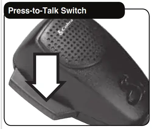
![]() To transmit:
To transmit:
- Select the desired channel.
- The receiver and transmitter are controlled by the Press-to-Talk switch on the microphone. Press the switch and the transmitter is activated; release
switch to receive. When transmitting (on a clear channel), hold the microphone two inches from the mouth and speak clearly in a normal voice.
Maintenance/Adjustment
Your Cobra CB transceiver is specifically designed for the environment encountered in mobile installations. The use of all-solid-state circuitry and its lightweight result in high reliability. Should a failure occur, however, review the following, then if necessary, replace parts only with identical parts? Do not substitute.
- Check connections to the source of power and make sure it is the 13.8 VDC required to operate your radio.
- Check the fuses in the DC power cord. The main power lead (red) has a two amp 3AG type fuse in its holder. Use only the above-specified type and size fuse for maximum protection. Failure to do so will void the warranty.
- Make certain the microphone is properly plugged in.
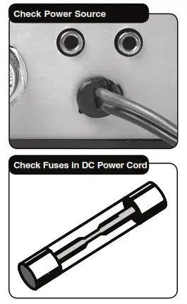
- Make certain the antenna is properly assembled and connected. If you are unable to correct the problem, refer to product service on page 14 for the correct procedure for warranty and post-warranty service from Cobra.
The Cobra 19 Series radio transceiver represents one of the most advanced AM two-way radios for use as a Class D station in the Citizens Radio Service.
This unit features advanced Phase Lock Loop (PLL) circuitry providing complete cover age of all 40 CB channels.
| CB Channel |
Channel Frequency in MHz |
| 1 | 27.215 |
| 2 | 26.975 |
| 3 | 26.985 |
| 4 | 27.005 |
| 5 | 27.015 |
| 6 | 27.025 |
| 7 | 27.035 |
| 8 | 27.055 |
| 9 | 27.065 |
| 10 | 27.075 |
| 11 | 27.085 |
| 12 | 27.105 |
| 13 | 27.115 |
| 14 | 27.125 |
| 15 | 27.135 |
| 16 | 27.155 |
| 17 | 27.165 |
| 18 | 27.175 |
| 19 | 27.185 |
| 20 | 27.205 |
| CB Channel |
Channel Frequency in MHz |
| 21 | 27.215 |
| 22 | 27.225 |
| 23 | 27.255 |
| 24 | 27.235 |
| 25 | 27.245 |
| 26 | 27.265 |
| 27 | 27.275 |
| 28 | 27.285 |
| 29 | 27.295 |
| 30 | 27.305 |
| 31 | 27.315 |
| 32 | 27.325 |
| 33 | 27.335 |
| 34 | 27.345 |
| 35 | 27.355 |
| 36 | 27.365 |
| 37 | 27.375 |
| 38 | 27.385 |
| 39 | 27.395 |
| 40 | 27.405 |
General
| Channels | CB — 40 CH |
| Frequency Range | CB — 26.965 to 27.405 MHZ |
| Frequency Tolerance | 0.005 % |
| Frequency Control | PLL (Phase Lock Loop) Synthesizer |
| Operating Temperature Range | -30° C TO + 65° C |
| Microphone | Plug-in Condenser |
| Input Voltage | 13.8VDC nom. (negative ground) |
| Current Drain | Transmit: AM full mod., 1.4A (maximum) Receive: Squelched, 0.9 A; full audio output, 1.2A (nominal) |
| Size | 1.75″ H x 4.5″ W x 7″ D |
| Weight | 3.25 lbs. |
| Antenna Connector | UHF: SO-239 |
| Meter | LCD’s; indicates relative power output and received signal strength |
Transmitter
| Power Output | 4 watts |
| Modulation | AM (Amplitude Modulation) |
| Frequency Response | 300 to 3000 Hz |
| Output Impedance | 50 ohms, unbalanced |
Receiver
| Sensitivity | Less than 1 µV for 10dB (S+N) |
| Selectivity | 6 dB @ 7 KHz, 60 dB @ 10KHz |
| Image Rejection | 60 dB, typical |
| Adjacent-Channel Rejection | 50 dB, typical |
| Automatic Noise Limiter | Built-in |
Limited One-Year Warranty
Secondary Icons
Warranty Terms:
Cobra warrants your product against all defects in materials and workmanship for a period of one (1) year from the date of original purchase.
Cobra, at our sole discretion, will repair or replace your product (with the same or comparable product) free of charge.
Cobra will not pay shipping charges that you incur for sending your product to us. Products received COD will be refused.
To make a warranty claim, we will require proof or purchase in the form of an invoice or receipt. No proof of purchase is required for factory direct purchases.
Warranty Exclusions: Warranty does not apply to your product under any of the following conditions:
1. The serial number has been removed or modied. 2. Your product has been subjected to misuse or damage (including water damage, physical abuse, and/or improper installation). 3. Your product has been modied in any way. 4. Your receipt or proof-of-purchase is from a non-authorized dealer or
internet auction site including E-bay, U-bid, or other non-authorized resellers.
LIMITATION OF WARRANTY: EXCEPT AS EXPRESSLY PROVIDED HEREIN, YOU ARE ACQUIRING THE PRODUCT “AS IS” AND “WHERE-IS”, WITHOUT REPRESENTATION OR WARRANTY. COBRA SPECIFICALLY DISCLAIMS ANY REPRESENTATION OR WARRANTY INCLUDING, BUT NOT LIMITED TO THOSE CONCERNING THE MERCHANTABILITY AND SUITABILITY OF THE PRODUCT FOR A PARTICULAR PURPOSE. COBRA SHALL NOT BE LIABLE FOR CONSEQUENTIAL, SPECIAL OR INCIDENTAL DAMAGES INCLUDING, WITHOUT LIMITATION, DAMAGES ARISING OUT OF THE USE, MISUSE OR MOUNTING OF THE PRODUCT.
The above limitations or exclusions shall be limited to the extent they violate the laws of any particular state. Cobra is not responsible for products lost in shipment between the owner and our service center. General Warranty Information
Each product we manufacture is covered by our factory warranty. While each product may have unique components and policy, the general guideline below will apply to most Cobra products. All Cobra products purchased factory-direct or from our Authorized Resellers will come with a full one to three (1-3) year warranty from the date of the original retail purchase (see policy statement above for full warranty details and exclusions).
Standard accessories packaged with each model will have a one-year factory warranty.
Accessory items have a one-year factory warranty.
Shipping to our facility is not covered in our warranty. Return shipping is included within the US.
This warranty is non-transferrable.
For the sake of clarity, ‘repair or replace the Product or its defective part’ does not include removal or installation work, costs or expenses which include but are not limited to labor costs or expenses. Cobra will not be responsible for lost packages.
If you have any questions about the operation or installing your new Cobra product, PLEASE CONTACT COBRA FIRST…do not return this product to any retail store. The contact information for Cobra will vary depending on the country in which you purchased and utilize the product. For the latest contact information, please go to www.cobra.com/support For products purchased in the U.S.A. you may call 800-543-1608. For products purchased in the U.S.A., if your product should require factory service, please please go to www.cobra.com/support and follow the instructions for returning your product to the Cobra Factory Service Department for service. Should there be any problems with this product or further information is needed on its features please visit www.cobra.comforsupport, frequently asked questions, Declarations of Conformity, and full manuals.
For Products Purchased Outside the U.S.A. or Canada
• Please contact your local dealer for product service information.
For Products Used in Canada
• Industry Canada Notice
This device complies with Industry Canada license-exempt RSS standard(s). Operation is subject to the following two conditions:
(1) this device may not cause interference, and (2) this device must accept any interference, including interference that may cause undesired operation of the device.
Customer Assistance
Ordering Info
• You can and quality Cobra products and accessories at your local Cobra dealer, or in the U.S.A., you can order directly from Cobra.
Please visit www.cobra.com
Web orders will normally ship the next business day if received by us before 2:00 PM Eastern Time. Orders do not ship on weekends or holidays. All standard deliveries are Monday-Friday only. Saturday delivery can be requested in certain areas of the country for an additional shipping fee by calling Sales at 800-543-1608. Certain orders may require additional days to process prior to shipping. Holidays may also impact processing and shipping time frames. Occasionally, items may not ship due to inventory depletion. If you need your item to be expedited, we recommend calling Sales at 800-543-1608.
Order Acceptance
Once your order has been accepted and processed, you will receive an email that will include the shipping carrier and tracking information.
Shipping and Delivery
Free ground shipping is included to 48 states. Hawaii, Alaska, and Puerto Rico ship based on the assessed fee at checkout.
We require a physical address for shipping. Sorry, no P.O. Boxes or APO/FPO addresses. Please select 2-day or next-day air for shipments to Hawaii or Alaska. Shipping charges are calculated on a per-product basis. Please make note of the shipping charges associated with each item. ** For safety reasons, we cannot ship power packs/Jumpacks via air delivery methods. These items are available to ship via ground service only. **For your protection, some orders may require a signature for delivery.
NOTES……..
Customer Assistance
Customer Assistance Should you encounter any problems with this product, or do not understand its many features, please refer to this owner’s manual. If you require further assistance after reading this manual, Cobra Electronics offers the following customer assistance services:
Monday-Friday 9:00 AM- 5:00 PM EST Call: 800-543-1608
SERVICE
Monday-Thursday 9:OOAM-5:OOPM EST Call: 800-543-1608
Office: 6500 West Cortland Street, Chicago, IL, 60707
Have questions?
We can help. Contact us at 800-543-1608 M-F 9:00 AM-5 PM EST
For Assistance Outside the U.S.A. Contact Your Local Dealer
©2021 Cobra ®
Electronics Corporation
Chicago, Illinois 60707 USA
www.cobra.com
6500 West Cortland Street
For more information or to order any of our products, please visit our website: www.cobra.com
Cobra ® , Nothing Comes Close to a Cobra ® and the snake design are registered trademarks of Cobra Electronics Corporation, USA. Cobra Electronics Corporation ™ is a trademark of Cobra Electronics Corporation, USA.