User Manual
![]()
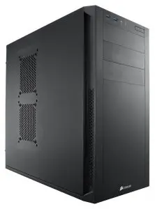
Corsair CARBIDE Series 200R Compact ATX Case
THANK YOU
Thank you for purchasing a Corsair® Carbide Series® 200R. With its elegant design and extensive feature set, 200R is a great case for beginning builders, or anybody looking for a compact, easy-to-use case.
Easy builds
Less work. More play. Build with the Carbide Series 200R and the only time you’ll need to pick up a screwdriver is to install the motherboard.
- Side panel thumbscrews
- PCI-E expansion card thumbscrew mounts
- Tool-free SSD, hard drive, and optical drive installation
- Cutouts for cable routing and CPU cooling
Easy to expand, and easy to cool
Carbide Series 200R is compact, but it’s designed to let you build high-performance systems with massive storage, extra graphics performance, and superior cooling and ventilation.
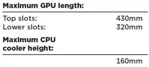
- Seven PCI-E slots with room for cards up to 320mm long
- Install up to four hard drives and four SSDs at once
- Up to eight fan mounts (depending on hard drive configuration)
Easy to use
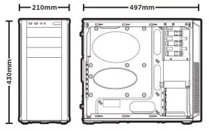
The mid-tower form factor combines room for expandability and out-of-the-way exterior dimensions.
- Front panel USB 3.0, headphone and microphone ports
- Dust filters behind the front intake fans help keep the interior clean
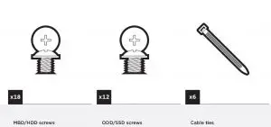
CONTENTS
CARBIDE SERIES® 200R MID-TOWER CASE
BRILLIANT DESIGN, INSIDE AND OUT ™
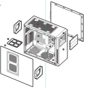
- (A) Dual 120mm/140mm fan mounts compatible with 240mm/280mm radiators
- (B) Dual 120mm/140mm fan mounts
- (C) USB 3.0 (x2) Headphone/Mic, Power/Reset
- (D) Dual 120mm fan mounts
- (E) CPU backplate cutout
- (F) Built-in cable routing cutouts
- (G) Tool-free optical drive bays
- (H) Tool-free 3.5″ hard drive cage with 2.5″ compatibility
- (I) Seven expansion slots for GPUs
- (J) Removable dust filters
- (K) Built-in cable routing channel
1. Removing the side panels
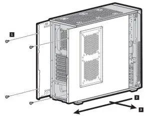
Unscrew thrumbscrews and remove, then pull side panels outward
2. Installing the motherboard
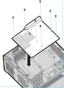
- Install your motherboard’s I/O shield (see motherboard manual for guidance)
- Align motherboard with the standos in the case
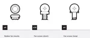
- Secure with included screws (MBD/HDD screws)
3. Installing the Power Supply (PSU)
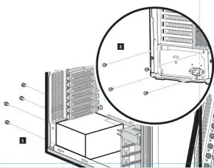
- Place PSU on the bottom of the case
- Align holes & secure with screws
- NOTE: PSU can be installed in either fan up or fan down orientation
4. Installing the PCI-E/PCI Cards
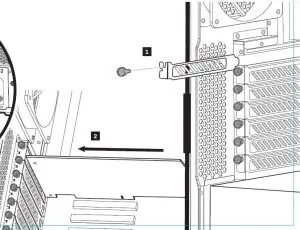
- Remove thumbscrews and corresponding slot cover(s)
- Install the add-on card & secure with thumbscrew
5. Installing 5.25″ Drive/Devices
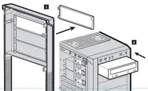
- Remove the front panel blank for the 5.25″ drive bay
- Insert the drive, pulling back the tool-free latch until it aligns with the mounting holes on your device, then release
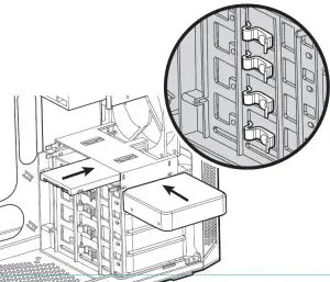
6. Installing 3.5″ HDD/ 2.5″ SSD
7. Attach case fan cables to motherboard headers
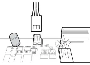
- See motherboard manual for fan header locations
8. Installing front I/O connectors
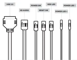
- See motherboard manual for front panel header locations and pin-outs
![]()
46221 Landing Parkway • Fremont • California • 94538 • USA
© 2012 Corsair Components, Inc. All rights reserved. Corsair, the sails logo, and Carbide Series are registered trademarks in the United States and/or other countries.
All other trademarks are the property of their respective owners. Product may vary slightly from those pictured. Document Number: 49-000178 revAA