DAIKIN Wireless Remote Controller Kit Instruction Manual

BRC4C82
1. SAFETY CONSIDERATIONS
Please read these “SAFETY CONSIDERATIONS” carefully before installing air conditioning equipment and be sure to install it correctly. After completing the installation, make sure that the unit operates properly during the start-up operation.
Please instruct the customer on how to operate the unit and keep it maintained.
Also, inform customers that they should store this installation manual along with the operation manual for future reference.
This air conditioner comes under the term “appliances not accessible to the general public”.
Meaning of warning, caution and note symbols.

- Perform installation work in accordance with this installation manual.
Improper installation may result in electric shocks or fire. - Be sure to use only the specified accessories and parts for installation work.
Failure to use the specified parts may result in, electric shocks, fire or the unit falling. - Before touching electrical parts, turn off the unit.
- Do not touch the switch with wet fingers.
Touching a switch with wet fingers can cause electric shock.
- Refer also to the installation manuals attached to the indoor unit and the decoration panel.
- Confirm that the following conditions are satisfied prior to installation.
Ensure that nothing interrupts the operation of the wireless remote controller. (Ensure that there is neither a source of light nor fluorescent lamp near the receiver. Also, ensure that the receiver is not exposed of direct sunlight.)
Ensure that the operation display lamp and other indicators are easy to see.
- The installation position of this receiver is one corner of the decoration panel. Therefore, confirm that its position is set so that the signal from the wireless remote controller can be easily transmitted and its display can be easily seen.
- If both this kit and fresh air intake kit are installed, only one duct chamber shall be used. Refer to the installation manual of the fresh air intake kit (optional hand book).
2. BEFORE INSTALLATION
2-1 ACCESSORIES
Check if the following accessories are included with the unit.
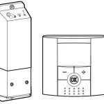
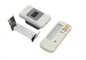
| Name | (1) Receiver | (2) Wireless remote controller | (3) Remote controller holder |
| Quantity | 1 pc. | 1 pc. | 1 pc. |
| Shape |  |
 |
 |
|
Name |
(4) Dry cell battery LR03 (AM4) | (5) Unit No. label | (6) Screw for install- ing remote con-troller holder |
| Quantity | 2 pcs. | 1 pc. | 2 pcs. |
| Shape |  |
 |
 |
| Name | (7) Mounting screw (Black) | (8) Mounting screw | (9) Paper pattern printing |
| Quantity | 2 pcs. | 2 pcs. | 1 pc. |
| Shape |  |
 |
 |
| Name | (10) Winged bar | (11) Operation manual | (12) Installation manual |
| Quantity | 1 pc. | 1 pc. | 1 pc. |
| Shape |  |
 |
|
2-2 NOTE TO THE INSTALLER
Be sure to instruct the customer how to properly operate the system showing him/her the attached operation manual.
3. REMOTE CONTROLLER INSTALLATION
<Installing wireless remote controller>
- Do not throw the remote controller or impose large shocks.
Also, do not store where it may be exposed to moisture or direct sunlight. - When operating, point the transmitting part of the remote controller in the direction of the receiver.
- The direct transmitting distance of the remote controller is approximately 23 ft..
- The signal cannot be transmitted if something such as curtains blocks the receiver and the remote controller.
- Installing to a wall or a pillar
- Fix the remote controller holder (3) with the screws (6).
- Slide the remote controller (2) into the remote controller holder (3) from the top.
- How to put the dry cell batteries
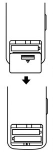
- Remove the back cover of the remote controller (2) to the direction pointed by the arrow mark.
- Put the dry cell batteries. Use two LR03 dry cell batteries (4). Put the dry cell batteries (4) correctly to fit their (+) and (–).
- Close the back cover as before.

4. RECEIVER INSTALLATION
- Do not install more than 3 receivers in the vicinity of one another.
- With 4 or more units, there is always the possibility of malfunction.
4-1. Preparations before installation
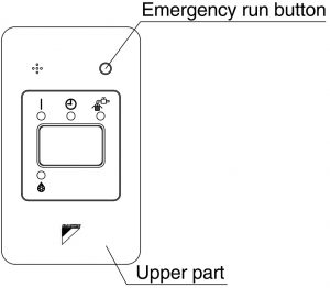
Remove the upper part of the receiver (1).
- Insert the screwdriver (–) here and gently work off the upper part of the receiver (1).
4-2. Determination of address and MAIN/SUB remote controller
If setting multiple wireless remote controllers to operate in 1 room, perform address setting for the receiver and the wireless remote controller. If setting multiple wired remote controllers in 1 room, change the MAIN/SUB switch of the receiver.
4-3. Setting procedure
- Setting the receiver
Set the wireless address switch (SS2) on the PC-board according to the table below.
| Unit No. | No.1 | No.2 | No.3 |
| Wireless address switch (SS2) |  |
 |
 |

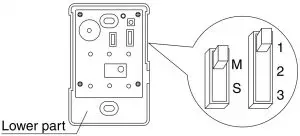
Change the setting so that the internal electronic equipments are not damaged with a pen etc.
When using both a wired and a wireless remote controller for 1 indoor unit, the wired controller should be set to MAIN.
Therefore, set the MAIN/SUB switch (SS1) of the receiver to SUB.
| MAIN | SUB | |
| MAIN/ SUB switch (SS1) |  |
 |
4-4. Receiver installation
Be sure to turn off the power before installation.
<Precautions on transmission wiring>
- When wiring, run the wiring away the power supply wiring in order to avoid receiving electric noise (external noise).
- When wiring, refer to the wiring diagram of indoor unit (attached to indoor unit) as well.
WIRING SPECIFICATION
| Wiring type | Sheathed wire (2 wire) |
| Size | AWG18-16 |
| Wiring length | Max 650 ft. (See Note) |
Keep wires to less than 650 ft. total when using 2 remote controllers (wired or wireless) and when not.
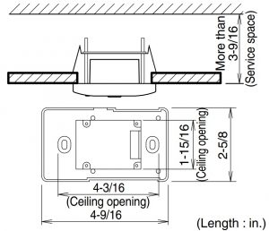
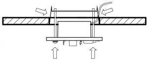
4-5. Attaching the receiver (for ceiling installation)
- Prepare the ceiling for the receiver.
- Open a hole in the ceiling for the receiver. (Use paper pattern printing (9)).
- Open a hole in the ceiling for the receiver. (Use paper pattern printing (9)).
- Wire the indoor unit and fix the lower part.
- Install the winged bar (10) to the lower part and fit the part with the screws (8). Then, wire (field supplied) accordingly. (Connect the P1 and P2 terminals on the rear of the lower part to the P1 and P2 terminals on the indoor unit. The P1 and P2 terminals have no polarity.)
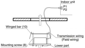
- Insert the lower part into the opening in the ceiling, first by pressing the wings inward to fit the hole and then by pushing from the screws (8) until it sits flat on the ceiling.
- Tighten the screws (8) until the lower part is fixed in place.
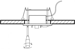
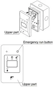
(Tighten both screws (8) evenly. Overtightening may deform the case and possibly make it harder to install the upper part.) - Attach the upper part of receiver (1).
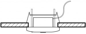
(Install the upper part on the lower part being careful parts are facing in the correct direction. After installation,turn on the power, and test emergency run button.)
- Install the winged bar (10) to the lower part and fit the part with the screws (8). Then, wire (field supplied) accordingly. (Connect the P1 and P2 terminals on the rear of the lower part to the P1 and P2 terminals on the indoor unit. The P1 and P2 terminals have no polarity.)


4-6 Attaching the receiver (for wall mounting)
- Wire the indoor unit.
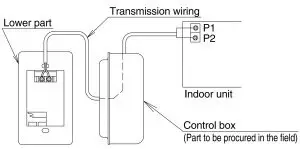
(Connect the P1 and P2 terminals on the rear of the lower part to the P1 and P2 terminals on the indoor unit. Neither of the terminals is polarized, so it is not important if connections are crossed.) - Fix the lower part.
- Install the lower part on the control box (field supplied part). (Select as flat a place as possible to install the lower part. Also, be aware of the fact that over tightening the screws (7)may deform the case and possibly make it harder to install the upper part.)
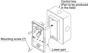
- Install the lower part on the control box (field supplied part). (Select as flat a place as possible to install the lower part. Also, be aware of the fact that over tightening the screws (7)may deform the case and possibly make it harder to install the upper part.)
- Attach the upper part of remote controller.
(Install the upper part on the lower part being careful parts are facing in the correct direction. After installation, turn on the power, and test emergency run button.)
NOTE
- The control box and wiring are not included.
- Do not directly touch the PC-board with your hand.
4-7. Setting the address of wireless remote controller (It is factory set to “1”.)
<Setting from the remote controller>
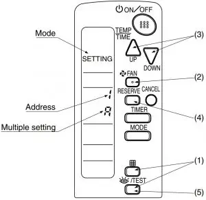
- Hold down the “

- Press the “

- Press the “


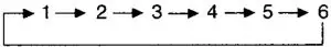
Address can be set from 1 to 6, but set it from 1 to 3 and to same address as the receiver. (The receiver does not work with address from 4 to 6.) - Press the “

- Push the “


<Multiple settings A/b>
When the indoor unit is being operating by outside control (central remote controller, etc.), it sometimes does not respond to ON/OFF and temperature setting commands from this remote controller. Check what setting the customer wants and make the multiple setting as shown below.
| Remote controller | Indoor unit | ||
| Multiple setting | Remote controller display | To control other air conditions and units | For other than on left |
| A: Standard | All items dis- played. | Commands other than ON/OFF and temperature setting accepted. (1 LONG BEEP or 3 SHORT BEEPS emitted) | |
| b: Multi System | Operations remain displayed shortly after execution | All commands accepted. (2 SHORT BEEPS) | |
4-8. Stick the Unit No. label on the receiver and the back of the wireless remote controller.
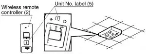
Set the Unit No. of the receiver and the wireless remote controller to be equal. If the settings differ, the signal from the remote controller cannot be transmitted.
5. FIELD SETTING
If optional accessories are mounted on the indoor unit, the indoor unit setting may have to be changed. Refer to the instruction manual (optional hand book ) for each optional accessory.
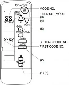
Procedure
- When in the normal mode, press the “
- Select the desired MODE NO. with the “

- Push the “
- Push the “
- Push the“
- Push the “

| MODE NO. | FIRST CODE NO. | DESCRIPTION OF SETTING | |
| 10 | 0 | Filter Contamination-Heavy/Light (Setting for spacing time of display time to clean air filter) (Setting for when filter contamination is heavy, and spacing time of display time to clean air filter is to be halved) | Long-life type |
| Standard type | |||
| 3 | Spacing time of display time to clean air filter count (Setting for when the filter sign is not to be displayed) | ||
| 12 (VRV system) | 1 | ON/OFF input from outside (Set to enable starting/ stopping from remote.) | |
| 2 | Thermostat differential changeover (Set when using remote controller thermostat sensor.) | ||
| MODE NO. | FIRST CODE NO. | SECOND CODE NO. | ||||
| 01 | 02 | 03 | ||||
| 10 | 0 | Light | Approx. 2,500 hours | Heavy | Approx. 1,250 hours | — |
| Approx. 200 hours | Approx. 100 hours | |||||
| 3 | Display | Do not display | — | |||
| 12 (VRV system) | 1 | Forced OFF input | ON/OFF | — | ||
| 2 | 2°F | 1°F | — | |||
The SECOND CODE NO. is factory set to “01”.
Do not use any settings not listed in the table.
For group control with a wireless remote controller, initial settings for all the indoor units of the group are equal. (For group control, refer to the installation manual attached to the indoor unit for group control.)
6. TEST OPERATION
- Perform test operation according to the instructions in the installation manual attached to the indoor unit.
- After refrigerant piping, drain piping, and electric wiring, operate according to the table to protect the unit.
- Refer to a malfunction code in the installation manual attached to the outdoor unit if it does not operate.
- Refer to the installation manual attached to the outdoor unit for individual operation system types.
| Order | Operation |
| (1) (2) (3) (4) (5) (6) (7) (8) |
Open gas side stop valve. Open liquid side stop valve. Electrify crank case heater for 6 hours. Set to cooling with the remote controller and push “  Push“  Push“  Push“ Confirm its function according to the operation manual. |