DEWALT 20V 7" (180 mm) Variable Speed Rotary
Polisher Instruction Manual
Definitions: Safety Alert Symbols and Words
This instruction manual uses the following safety alert symbols and words to alert you to hazardous situations and your risk of personal injury or property damage.
![]() DANGER: Indicates an imminently hazardous situation which, if not avoided, will result in death or serious injury.
DANGER: Indicates an imminently hazardous situation which, if not avoided, will result in death or serious injury.
![]() WARNING: Indicates a potentially hazardous situation which, if not avoided, could result in death or serious injury.
WARNING: Indicates a potentially hazardous situation which, if not avoided, could result in death or serious injury.
![]() CAUTION: Indicates a potentially hazardous situation which, if not avoided, may result in minor or moderate injury.
CAUTION: Indicates a potentially hazardous situation which, if not avoided, may result in minor or moderate injury.
(Used without word) Indicates a safety related message.
![]() NOTICE: Indicates a practice not related to personal injury which, if not avoided, may result in property damage.
NOTICE: Indicates a practice not related to personal injury which, if not avoided, may result in property damage.
1 Battery
2 Battery release button
3 Speed control wheel
4 Cushion tool rest
5 Variable speed trigger switch
6 Spindle lock button
7 Auxiliary handle
8 Spindle
9 Soft rubber gear case cover
10 Wool ingestion shield
11 Lock button
![]() WARNING: Read all safety warnings and all instructions. Failure to follow the warnings and instructions may result in electric shock, fire and/or serious injury.
WARNING: Read all safety warnings and all instructions. Failure to follow the warnings and instructions may result in electric shock, fire and/or serious injury.
![]() WARNING: To reduce the risk of injury, read the instruction manual.
WARNING: To reduce the risk of injury, read the instruction manual.
If you have any questions or comments about this or any product, call D e WALT toll free at: (1-800-433-9258).
GENERAL POWER TOOL SAFETY WARNINGS
![]() WARNING: Read all safety warnings, instructions, illustrations and specifications provided with this power tool. Failure to follow all instructions listed below may result in electric shock, fire and/or serious injury.
WARNING: Read all safety warnings, instructions, illustrations and specifications provided with this power tool. Failure to follow all instructions listed below may result in electric shock, fire and/or serious injury.
SAVE ALL WARNINGS AND INSTRUCTIONS FOR FUTURE REFERENCE.
The term “power tool” in the warnings refers to your mains-operated (corded) power tool or battery-operated (cordless) power tool.
- Work Area Safety
- a ) Keep work area clean and well lit. Cluttered or dark areas invite accidents.
- b ) Do not operate power tools in explosive atmospheres, such as in the presence of flammable liquids, gases or dust. Power tools create sparks which may ignite the dust or fumes.
- c ) Keep children and bystanders away while operating a power tool. Distractions can cause you to lose control.
- Electrical Safety
- a ) Power tool plugs must match the outlet. Never modify the plug in any way. Do not use any adapter plugs with earthed (grounded) power tools. Unmodified plugs and matching outlets will reduce risk of electric shock.
- b ) Avoid body contact with earthed or grounded surfaces, such as pipes, radiators, ranges and refrigerators. There is an increased risk of electric shock if your body is earthed or grounded.
- c ) Do not expose power tools to rain or wet conditions. Water entering a power tool will increase the risk of electric shock.
- d ) Do not abuse the cord. Never use the cord for carrying, pulling or unplugging the power tool. Keep cord away from heat, oil, sharp edges or moving parts. Damaged or entangled cords increase the risk of electric shock.
- e ) When operating a power tool outdoors, use an extension cord suitable for outdoor use. Use of a cord suitable for outdoor use reduces the risk of electric shock.
- f ) If operating a power tool in a damp location is unavoidable, use a ground fault circuit interrupter (GFCI) protected supply. Use of a GFCI reduces the risk of electric shock.
- Personal Safety
- a ) Stay alert, watch what you are doing and use common sense when operating a power tool. Do not use a power tool while you are tired or under the influence of drugs, alcohol or medication. A moment of inattention while operating power tools may result in serious personal injury.
- b ) Use personal protective equipment. Always wear eye protection. Protective equipment such as a dust mask, non-skid safety shoes, hard hat, or hearing protection used for appropriate conditions will reduce personal injuries.
- c ) Prevent unintentional starting. Ensure the switch is in the off-position before connecting to power source and/or battery pack, picking up or carrying the tool. Carrying power tools with your finger on the switch or energizing power tools that have the switch on invites accidents.
- d ) Remove any adjusting key or wrench before turning the power tool on. A wrench or a key left attached to a rotating part of the power tool may result in personal injury.
- e ) Do not overreach. Keep proper footing and balance at all times. This enables better control of the power tool in unexpected situations.
- f ) Dress properly. Do not wear loose clothing or jewelry. Keep your hair, clothing and gloves away from moving parts. Loose clothes, jewelry or long hair can be caught in moving parts.
- g ) If devices are provided for the connection of dust extraction and collection facilities, ensure these are connected and properly used. Use of dust collection can reduce dust-related hazards.
- h ) Do not let familiarity gained from frequent use of tools allow you to become complacent and ignore tool safety principles. A careless action can cause severe injury within a fraction of a second.
- Power Tool Use and Care
- a ) Do not force the power tool. Use the correct power tool for your application. The correct power tool will do the job better and safer at the rate for which it was designed.
- b ) Do not use the power tool if the switch does not turn it on and off. Any power tool that cannot be controlled with the switch is dangerous and must be repaired.
- c ) Disconnect the plug from the power source and/or remove the battery pack, if detachable, from the power tool before making any adjustments, changing accessories, or storing power tools. Such preventive safety measures reduce the risk of starting the power tool accidentally.
- d ) Store idle power tools out of the reach of children and do not allow persons unfamiliar with the power tool or these instructions to operate the power tool. Power tools are dangerous in the hands of untrained users.
- e ) Maintain power tools and accessories. Check for misalignment or binding of moving parts, breakage of parts and any other condition that may affect the power tool’s operation. If damaged, have the power tool repaired before use. Many accidents are caused by poorly maintained power tools.
- f ) Keep cutting tools sharp and clean. Properly maintained cutting tools with sharp cutting edges are less likely to bind and are easier to control.
- g ) Use the power tool, accessories and tool bits etc. in accordance with these instructions, taking into account the working conditions and the work to be performed. Use of the power tool for operations different from those intended could result in a hazardous situation.
- h ) Keep handles and grasping surfaces dry, clean and free from oil and grease. Slippery handles and grasping surfaces do not allow for safe handling and control of the tool in unexpected situations.
- Battery Tool Use and Care
- a ) Recharge only with the charger specified by the manufacturer. A charger that is suitable for one type of battery pack may create a risk of fire when used with another battery pack.
- b ) Use power tools only with specifically designated battery packs. Use of any other battery packs may create a risk of injury and fire.
- c ) When battery pack is not in use, keep it away from other metal objects, like paper clips, coins, keys, nails, screws or other small metal objects, that can make a connection from one terminal to another. Shorting the battery terminals together may cause burns or a fire.
- d ) Under abusive conditions, liquid may be ejected from the battery; avoid contact. If contact accidentally occurs, flush with water. If liquid contacts eyes, additionally seek medical help. Liquid ejected from the battery may cause irritation or burns.
- e ) Do not use a battery pack or tool that is damaged or modified. Damaged or modified batteries may exhibit unpredictable behavior resulting in fire, explosion or risk of injury.
- f ) Do not expose a battery pack or tool to fire or excessive temperature. Exposure to fire or temperature above 265 °F (130 °C) may cause explosion.
- g ) Follow all charging instructions and do not charge the battery pack or tool outside the temperature range specified in the instructions. Charging improperly or at temperatures outside the specified range may damage the battery and increase the risk of fire.
- Service
- a ) Have your power tool serviced by a qualified repair person using only identical replacement parts. This will ensure that the safety of the power tool is maintained.
- b ) Never service damaged battery packs. Service of battery packs should only be performed by the manufacturer or authorized service providers.
Safety Instructions for All Operations
- a ) This power tool is intended to function as a polisher. Read all safety warnings, instructions, illustrations and specifications provided with this power tool. Failure to follow all instructions listed below may result in electric shock, fire and/or serious injury.
- b ) Operations such as grinding, sanding, wire brushing or cutting-off are not recommended to be performed with this power tool. Operations for which the power tool was not designed may create a hazard and cause personal injury.
- c ) Do not use accessories which are not specifically designed and recommended by the tool manufacturer. Just because the accessory can be attached to your power tool, it does not assure safe operation.
- d ) The rated speed of the accessory must be at least equal to the maximum speed marked on the power tool. Accessories running faster than their rated speed can break and fly apart.
- e ) The outside diameter and the thickness of your accessory must be within the capacity rating of your power tool. Incorrectly sized accessories cannot be adequately guarded or controlled.
- f ) Threaded mounting of accessories must match the grinder spindle thread. For accessories mounted by flanges, the arbor hole of the accessory must fit the locating diameter of the flange. Accessories that do not match the mounting hardware of the power tool will run out of balance, vibrate excessively and may cause loss of control.
- g ) Do not use a damaged accessory. Before each use inspect the accessory such as abrasive wheels for chips and cracks, backing pad for cracks, tear or excess wear, wire brush for loose or cracked wires. If power tool or accessory is dropped, inspect for damage or install an undamaged accessory. After inspecting and installing an accessory, position yourself and by standers away from the plane of the rotating accessory and run the power tool at maximum no-load speed for one minute. Damaged accessories will normally break apart during this test time.
- h ) Wear personal protective equipment. Depending on application, use face shield, safety goggles or safety glasses. As appropriate, wear dust mask, hearing protectors, gloves and workshop apron capable of stopping small abrasive or workpiece fragments. The eye protection must be capable of stopping flying debris generated by various operations. The dust mask or respirator must be capable of filtrating particles generated by your operation. Prolonged exposure to high intensity noise may cause hearing loss.
- i ) Keep bystanders a safe distance away from work area. Anyone entering the work area must wear personal protective equipment. Fragments of workpiece or of a broken accessory may fly away and cause injury beyond immediate area of operation.
- j ) Position the cord clear of the spinning accessory. If you lose control, the cord may be cut or snagged and your hand or arm may be pulled into the spinning accessory.
- k ) Never lay the power tool down until the accessory has come to a complete stop. The spinning accessory may grab the surface and pull the power tool out of your control.
- l ) Do not run the power tool while carrying it at your side. Accidental contact with the spinning accessory could snag your clothing, pulling the accessory into your body.
- m ) Regularly clean the power tool’s air vents. The motor’s fan will draw the dust inside the housing and excessive accumulation of powdered metal may cause electrical hazards.
- n ) Do not operate the power tool near flammable materials. Sparks could ignite these materials.
- o ) Do not use accessories that require liquid coolants. Using water or other liquid coolants may result in electrocution or shock.
Further Safety Instructions for All Operations
Kickback and Related Warnings
Kickback is a sudden reaction to a pinched or snagged rotating wheel, backing pad, brush or any other accessory. Pinching or snagging causes rapid stalling of the rotating accessory which in turn causes the uncontrolled power tool to be forced in the direction opposite of the accessory’s rotation at the point of the binding.
For example, if an abrasive wheel is snagged or pinched by the workpiece, the edge of the wheel that is entering into the pinch point can dig into the surface of the material causing the wheel to climb out or kick out. The wheel may either jump toward or away from the operator, depending on direction of the wheel’s movement at the point of pinching. Abrasive wheels may also break under these conditions.
Kickback is the result of tool misuse and/or incorrect operating procedures or conditions and can be avoided by taking proper precautions as given below:
- a ) Maintain a firm grip on the power tool and position your body and arm to allow you to resist kickback forces. Always use auxiliary handle, if provided, for maximum control over kickback or torque reaction during start up. The operator can control torque reaction or kickback forces, if proper precautions are taken.
- b ) Never place your hand near the rotating accessory. Accessory may kickback over your hand.
- c ) Do not position your body in the area where power tool will move if kickback occurs. Kickback will propel the tool in direction opposite to the wheel’s movement at the point of snagging.
- d ) Use special care when working corners, sharp edges, etc. Avoid bouncing and snagging the accessory. Corners, sharp edges or bouncing have a tendency to snag the rotating accessory and cause
loss of control or kickback. - e ) Do not attach a saw chain woodcarving blade or toothed saw blade. Such blades create frequent kickback and loss of control.
Safety Warnings Specific for Polishing Operations
a ) Do not allow any loose portion of the polishing bonnet or its attachment strings to spin freely. Tuck away or trim any loose attachment strings. Loose and spinning attachment strings can entangle your fingers or snag on the workpiece.
Additional Specific Safety Instructions for Polishers
- Clean out your tool often, especially after heavy use. Dust and grit containing metal particles often accumulate on interior surfaces and could create an electric shock hazard.
- Do not operate this tool for long periods of time. Vibration caused by the operating action of this tool may cause permanent injury to fingers, hands and arms. Use gloves to provide extra cushion, take frequent rest periods and limit daily time of use.
- Ensure the switch is in the lock-off position when not in use and before connecting to the power source or battery pack.
Additional Safety Information
![]()
WARNING: Never modify the power tool or any part of it. Damage or personal injury could result.
![]()
WARNING: ALWAYS use safety glasses. Everyday eyeglasses are NOT safety glasses. Also use face or dust mask if operation is dusty. ALWAYS WEAR CERTIFIED SAFETY EQUIPMENT:
- ANSI Z87.1 eye protection (CAN/CSA Z94.3),
- ANSI S12.6 (S3.19) hearing protection,
- NIOSH/OSHA/MSHA respiratory protection.
![]()
WARNING: Some dust created by power sanding, sawing, grinding, drilling, and other construction activities contains chemicals known to the State of California to cause cancer, birth defects or other reproductive harm. Some examples of these chemicals are:
- lead from lead-based paints,
- crystalline silica from bricks and cement and other masonry products, and
- arsenic and chromium from chemically-treated lumber.
Your risk from these exposures varies, depending on how often you do this type of work. To reduce your exposure to these chemicals: work in a well ventilated area, and work with approved safety equipment, such as those dust masks that are specially designed to filter out microscopic particles.
- Avoid prolonged contact with dust from power sanding, sawing, grinding, drilling, and other construction activities. Wear protective clothing and wash exposed areas with soap and water. Allowing dust to get into your mouth, eyes, or lay on the skin may promote absorption of harmful chemicals.
![]() WARNING: Use of this tool can generate and/ or disperse dust, which may cause serious and permanent respiratory or other injury. Always use NIOSH/OSHA approved respiratory protection appropriate for the dust exposure. Direct particles away from face and body.
WARNING: Use of this tool can generate and/ or disperse dust, which may cause serious and permanent respiratory or other injury. Always use NIOSH/OSHA approved respiratory protection appropriate for the dust exposure. Direct particles away from face and body.
![]() WARNING: Always wear proper personal hearing protection that conforms to ANSI S12.6 (S3.19) during use. Under some conditions and duration of use, noise from this product may contribute to hearing loss.
WARNING: Always wear proper personal hearing protection that conforms to ANSI S12.6 (S3.19) during use. Under some conditions and duration of use, noise from this product may contribute to hearing loss.
![]() CAUTION: When not in use, place tool upside down using tool rests on a stable surface where it will not cause a tripping or falling hazard. Some tools with large battery packs will stand upright on the battery pack but may be easily knocked over.
CAUTION: When not in use, place tool upside down using tool rests on a stable surface where it will not cause a tripping or falling hazard. Some tools with large battery packs will stand upright on the battery pack but may be easily knocked over.
- Air vents often cover moving parts and should be avoided. Loose clothes, jewelry or long hair can be caught in moving parts.
BATTERIES AND CHARGERS
The battery pack is not fully charged out of the carton. Before using the battery pack and charger, read the safety instructions below and then follow charging procedures outlined. When ordering replacement battery packs, be sure to include the catalog number and voltage.
READ ALL INSTRUCTIONS
Important Safety Instructions for All Battery Packs
![]() WARNING: Read all safety warnings, instructions, and cautionary markings for the battery pack, charger and product. Failure to follow the warnings and instructions may result in electric shock, fire and/or serious injury.
WARNING: Read all safety warnings, instructions, and cautionary markings for the battery pack, charger and product. Failure to follow the warnings and instructions may result in electric shock, fire and/or serious injury.
- Do not charge or use the battery pack in explosive atmospheres, such as in the presence of flammable liquids, gases or dust. Inserting or removing the battery pack from the charger may ignite the dust or fumes.
- When battery pack is not in use, keep it away from other metal objects, like paper clips, coins, keys, nails, screws, or other small metal objects, that can make a connection from one terminal to another. Shorting the battery terminals together may cause burns or a fire.
- NEVER force the battery pack into the charger. DO NOT modify the battery pack in any way to fit into a non-compatible charger as battery pack may rupture causing serious personal injury. Consult the chart at the end of this manual for compatibility of batteries and chargers.
- Charge the battery packs only in D e WALT chargers.
- DO NOT splash or immerse in water or other liquids.
- Do not store or use the tool and battery pack in locations where the temperature may reach or exceed 104 °F (40 °C) (such as outside sheds or metal buildings in summer). For best life store battery packs in a cool, dry location.
NOTE: Do not store the battery packs in a tool with the trigger switch locked on. Never tape the trigger switch in the ON position. - Do not expose battery pack or tool/appliance to fire or excessive temperature. Exposure to fire or temperature above 265 °F (130 °C) may cause explosion.
- Do not incinerate the battery pack even if it is severely damaged or is completely worn out. The battery pack can explode in a fire. Toxic fumes and materials are created when lithium-ion battery packs are burned.
- If battery contents come into contact with the skin, immediately wash area with mild soap and water. If battery liquid gets into the eye, rinse water over the open eye for 15 minutes or until irritation ceases. If medical attention is needed, the battery electrolyte is composed of a mixture of liquid organic carbonates and lithium salts.
- Contents of opened battery cells may cause respiratory irritation. Provide fresh air. If symptoms persist, seek medical attention.
![]()
WARNING: Burn hazard. Battery liquid may be flammable if exposed to spark or flame.
![]() WARNING: Fire hazard. Never attempt to open the battery pack for any reason. If the battery pack case is cracked or damaged, do not insert into the charger. Do not crush, drop or damage the battery pack. Do not use a battery pack or charger that has received a sharp blow, been dropped, run over or damaged in any way (e.g., pierced with a nail, hit with a hammer, stepped on). Damaged battery packs should be returned to the service center for recycling.
WARNING: Fire hazard. Never attempt to open the battery pack for any reason. If the battery pack case is cracked or damaged, do not insert into the charger. Do not crush, drop or damage the battery pack. Do not use a battery pack or charger that has received a sharp blow, been dropped, run over or damaged in any way (e.g., pierced with a nail, hit with a hammer, stepped on). Damaged battery packs should be returned to the service center for recycling.
Storage Recommendations
- The best storage place is one that is cool and dry, away from direct sunlight and excess heat or cold.
- For long storage, it is recommended to store a fully charged battery pack in a cool dry place out of the charger for optimal results.
NOTE: Battery packs should not be stored completely depleted of charge. The battery pack will need to be recharged before use.
Battery Pack Cleaning Instructions
Dirt and grease may be removed from the exterior of the battery using a cloth or soft non-metallic brush. Do not use water or any cleaning solutions.
Fuel Gauge Battery Packs
Some DeWALT Mac Tools battery packs include a fuel gauge which consists of three green LED lights that indicate the level of charge remaining in the battery pack. The fuel gauge is an indication of approximate levels of charge remaining in the battery pack according to the following indicators:

To actuate the fuel gauge, press and hold the fuel gauge button. A combination of the three green LED lights will illuminate designating the level of charge left. When the level of charge in the battery is below the usable limit, the fuel gauge will not illuminate and the battery will need to be recharged.
NOTE: The fuel gauge is only an indication of the charge left on the battery pack. It does not indicate tool functionality and is subject to variation based on product components, temperature and end-user application.
For more information regarding fuel gauge battery packs, please contact 1-800-4-D e WALT (1-800-433-9258) or visit our website www.dewalt.com.
Transportation
![]()
WARNING: Fire hazard. Do not store or carry the battery pack so that metal objects can contact exposed battery terminals. For example, do not place the battery pack in aprons, pockets, tool boxes, product kit boxes, drawers, etc., with loose nails, screws, keys, etc. Transporting batteries can possibly cause fires if the battery terminals inadvertently come in contact with conductive materials such as keys, coins, hand tools and the like. The US Department of Transportation Hazardous Material Regulations (HMR) actually prohibit transporting batteries in commerce or on airplanes in carry-on baggage UNLESS they are properly protected from short circuits. So when transporting individual battery packs, make sure that the battery terminals are protected and well insulated from materials that could contact them and cause a short circuit.
NOTE: Li-ion batteries should not be put in checked baggage.
The RBRC® Seal
The RBRC® (Rechargeable Battery
Recycling Corporation) Seal on the nickel cadmium, nickel metal hydride or lithium-ion batteries (or battery packs) indicates that the costs to recycle these batteries (or battery packs) at the end of their useful life have already been paid by DeWALT. In some areas, it is illegal to place spent nickel cadmium, nickel metal hydride or lithium-ion batteries in the trash or municipal solid waste stream and the Call 2 Recycle® program provides an environmentally conscious alternative.
Call 2 Recycle, Inc., in cooperation with DeWALT and other battery users, has established the program in the United States and Canada to facilitate the collection of spent nickel cadmium, nickel metal hydride or lithium-ion batteries. Help protect our environment and conserve natural resources by returning the spent nickel cadmium, nickel metal hydride or lithium-ion batteries to an authorized D e WALT service center or to your local retailer for recycling. You may also contact your local recycling center for information on where to drop off the spent battery. RBRC® is a registered trademark of Call 2 Recycle, Inc.
Shipping the DeWALT FlEXVOlT™ Battery
The DeWALT FLEXVOLT™ battery has two modes: Use and shipping.
Use Mode: When the FLEXVOLT™ battery stands alone or is in a DeWALT 20V Max* product, it will operate as a 20V Max* battery. When the FLEXVOLT™ battery is in a 60V Max* or a 120V Max* (two 60V Max* batteries) product, it will operate as a 60V Max* battery.
Shipping Mode: When the cap is attached to the FLEXVOLT™ battery, the battery is in Shipping Mode.
Strings of cells are electrically disconnected within the pack resulting in three batteries with a lower Watt hour (Wh) rating as compared to one battery with a higher Watt hour rating. This increased quantity of three batteries with the lower Watt hour rating can exempt the pack from certain shipping regulations that are imposed upon the higher Watt hour batteries.
The battery label indicates two Watt hour ratings (see example). Depending on how the battery is shipped, the appropriate Watt hour rating must be used to determine the applicable shipping requirements. If utilizing the shipping cap, the pack will be considered 3 batteries at the Watt hour rating indicated for “Shipping”. If shipping without the cap or in a tool, the pack will be considered one battery at the Watt hour rating indicated next to “Use”.
Example of Use and Shipping Label Marking

For example, Shipping Wh rating might indicate 3 x 40 Wh, meaning 3 batteries of 40 Watt hours each. The Use Wh rating might indicate 120 Wh (1 battery implied).
Important Safety Instructions for All Battery Chargers
![]() WARNING: Read all safety warnings, instructions, and cautionary markings for the battery pack, charger and product. Failure to follow the warnings and instructions may result in electric shock, fire and/or serious injury.
WARNING: Read all safety warnings, instructions, and cautionary markings for the battery pack, charger and product. Failure to follow the warnings and instructions may result in electric shock, fire and/or serious injury.
- DO NOT attempt to charge the battery pack with any chargers other than a DeWALT charger. DeWALT chargers and battery packs are specifically designed to work together.
- These chargers are not intended for any uses other than charging D e WALT rechargeable batteries. Any other uses may result in risk of fire, electric shock or electrocution.
- Do not expose the charger to rain or snow.
- Pull by the plug rather than the cord when disconnecting the charger. This will reduce the risk of damage to the electric plug and cord.
- Make sure that the cord is located so that it will not be stepped on, tripped over or otherwise subjected to damage or stress.
- Do not use an extension cord unless it is absolutely necessary. Use of improper extension cord could result in risk of fire, electric shock or electrocution.
- When operating a charger outdoors, always provide a dry location and use an extension cord suitable for outdoor use. Use of a cord suitable for outdoor use reduces the risk of electric shock.
- An extension cord must have adequate wire size (AWG or American Wire Gauge) for safety. The smaller the gauge number of the wire, the greater the capacity of the cable, that is, 16 gauge has more capacity than 18 gauge. An undersized cord will cause a drop in line voltage resulting in loss of power and overheating. When using more than one extension to make up the total length, be sure each individual extension contains at least the minimum wire size. The following table shows the correct size to use depending on cord length and nameplate ampere rating. If in doubt, use the next heavier gauge. The lower the gauge number, the heavier the cord.
Minimum gauge for Cord sets

- Do not place any object on top of the charger or place the charger on a soft surface that might block the ventilation slots and result in excessive internal heat. Place the charger in a position away from any heat source. The charger is ventilated through slots in the top and the bottom of the housing.
- Do not operate the charger with a damaged cord or plug–have them replaced immediately.
- Do not operate the charger if it has received a sharp blow, been dropped or otherwise damaged in any way. Take it to an authorized service center.
- Do not disassemble the charger; take it to an authorized service center when service or repair is required. Incorrect reassembly may result in a risk of electric shock, electrocution or fire.
- Disconnect the charger from the outlet before attempting any cleaning. This will reduce the risk of electric shock. Removing the battery pack will not reduce this risk.
- NEVER attempt to connect 2 chargers together.
- The charger is designed to operate on standard 120V household electrical power. Do not attempt to use it on any other voltage. This does not apply to the vehicular charger.
![]() WARNING: Shock hazard. Do not allow any liquid to get inside the charger. Electric shock may result.
WARNING: Shock hazard. Do not allow any liquid to get inside the charger. Electric shock may result.
![]() WARNING: Burn hazard. Do not submerge the battery pack in any liquid or allow any liquid to enter the battery pack. Never attempt to open the battery pack for any reason. If the plastic housing of the battery pack breaks or cracks, return to a service center for recycling.
WARNING: Burn hazard. Do not submerge the battery pack in any liquid or allow any liquid to enter the battery pack. Never attempt to open the battery pack for any reason. If the plastic housing of the battery pack breaks or cracks, return to a service center for recycling.
![]() CAUTION: Burn hazard. To reduce the risk of injury, charge only D e WALT rechargeable battery packs. Other types of batteries may overheat and burst resulting in personal injury and property damage.
CAUTION: Burn hazard. To reduce the risk of injury, charge only D e WALT rechargeable battery packs. Other types of batteries may overheat and burst resulting in personal injury and property damage.
![]()
CAUTION: Under certain conditions, with the charger plugged into the power supply, the charger can be shorted by foreign material. Foreign materials of a conductive nature, such as, but not limited to, grinding dust, metal chips, steel wool, aluminum
foil or any buildup of metallic particles should be kept away from the charger cavities. Always unplug the charger from the power supply when there is no battery pack in the cavity. Unplug the charger before attempting to clean.
Charging a Battery
NOTE: To ensure maximum performance and life of lithium-ion battery packs, charge the battery pack fully before first use.
- Plug the charger into an appropriate outlet before inserting battery pack.
- Connect the charger and battery pack, making sure the battery is fully seated. The (charging) light will blink continuously indicating that the charging process has started.
- The completion of charge will be indicated by the light remaining ON continuously. The battery pack is fully charged and may be removed and used at this time or left in the charger.
NOTE: To remove the battery pack, some chargers require the battery pack release button to be pressed.

The red light will continue to blink, but a yellow indicator light will be illuminated during this operation. Once the battery pack has reached an appropriate temperature, the yellow light will turn off and the charger will resume the charging procedure.
A charger will not charge a faulty battery pack. The charger refusing to light could indicate a problem with the charger or a faulty battery pack.
NOTE: If the charger refuses to light, take the charger and battery pack to be tested at an authorized service center.
leaving the Battery Pack in the Charger
The charger and battery pack can be left connected with the charge indicator showing pack charged.
hot/Cold Pack Delay
When the charger detects a battery pack that is too hot or too cold, it automatically starts a Hot/Cold Pack Delay, suspending charging until the battery pack has reached an appropriate temperature. The charger then automatically switches to the pack charging mode. This feature ensures maximum battery pack life.
A cold battery pack may charge at a slower rate than a warm battery pack.
The DCB118 charger is equipped with an internal fan designed to cool the battery pack. The fan will turn on automatically when the battery pack needs to be cooled.
Never operate the charger if the fan does not operate properly or if ventilation slots are blocked. Do not permit foreign objects to enter the interior of the charger.
Electronic Protection System
Li-Ion tools are designed with an Electronic Protection System that will protect the battery pack against overloading, overheating or deep discharge.
The tool will automatically turn off if the Electronic Protection System engages. If this occurs, place the lithium-ion battery pack on the charger until it is fully charged.
Important Charging Notes
- Longest life and best performance can be obtained if the battery pack is charged when the air temperature is between 65 °F – 75 °F (18 ° C– 24 °C). DO NOT charge when the battery pack is below +40 °F (+4.5 °C), or above +104 °F (+40 °C). This is important and will prevent serious damage to the battery pack.
- The charger and battery pack may become warm to the touch while charging. This is a normal condition, and does not indicate a problem. To facilitate the cooling of the battery pack after use, avoid placing the charger or battery pack in a warm environment such as in a metal shed or an uninsulated trailer.
- If the battery pack does not charge properly:
- a. Check operation of receptacle by plugging in a lamp or other appliance;
- b. Check to see if receptacle is connected to a light switch which turns power off when you turn out the lights;
- c. Move the charger and battery pack to a location where the surrounding air temperature is approximately 65 °F – 75 °F (18 °C – 24 °C);
- d. If charging problems persist, take the tool, battery pack and charger to your local service center.
- The battery pack should be recharged when it fails to produce sufficient power on jobs which were easily done previously. DO NOT CONTINUE to use under these conditions. Follow the charging procedure. You may also charge a partially used pack whenever you desire with no adverse effect on the battery pack.
- Foreign materials of a conductive nature such as, but not limited to, grinding dust, metal chips, steel wool, aluminum foil, or any buildup of metallic particles should be kept away from charger cavities. Always unplug the charger from the power supply when there is no battery pack in the cavity. Unplug the charger before attempting to clean.
- Do not freeze or immerse the charger in water or any other liquid.
Charger Cleaning Instructions
![]()
WARNING: Shock hazard. Disconnect the charger from the AC outlet before cleaning. Dirt and grease may be removed from the exterior of the charger using a cloth or soft non-metallic brush. Do not use water or any cleaning solutions.
Wall Mounting
DCB107, DCB112, DCB113, DCB115, DCB118, DCB132
These chargers are designed to be wall mountable or to sit upright on a table or work surface. If wall mounting, locate the charger within reach of an electrical outlet, and away from a corner or other obstructions which may impede air flow. Use the back of the charger as a template for the location of the mounting screws on the wall. Mount the charger securely using drywall screws (purchased separately) at least 1” (25.4 mm) long, with a screw head diameter of 0.28–0.35” (7–9 mm), screwed into wood to an optimal depth leaving approximately 7/32” (5.5 mm) of the screw exposed. Align the slots on the back of the charger with the exposed screws and fully engage them in the slots.
Intended Use
The DCM849 heavy-duty polisher is designed for polishing painted or unfinished metal, fiberglass, and composite surfaces in professional applications. Common examples of use include but are not limited to: auto/marine/RV/motorcycle detailing and finish correction, boat construction and repair, and metal or concrete finishing.
DO NOT use under wet conditions or in presence of flammable liquids or gases.
DO NOT let children come into contact with the tool. Supervision is required when inexperienced operators use this tool.
ASSEMBLY AND ADJUSTMENTS
![]() WARNING: To reduce the risk of serious personal injury, turn unit off and remove the battery pack before making any adjustments or removing/installing attachments or accessories. An accidental start-up can cause injury.
WARNING: To reduce the risk of serious personal injury, turn unit off and remove the battery pack before making any adjustments or removing/installing attachments or accessories. An accidental start-up can cause injury.
Handles
Attaching Auxiliary Handle (Fig. A)
![]() WARNING: Before using the tool, check that the handle is tightened securely.
WARNING: Before using the tool, check that the handle is tightened securely.
Screw the auxiliary handle (7) tightly into one of the holes on either side of the gear case. The auxiliary handle should always be used to maintain control of the tool at all times.
Installation of the Bail Handle Assembly (Fig B)
- Place the bail handle 12 over the polisher gear case aligning the screws 13 with the threaded holes and the ears on the gear case with the slots in the bail handle assembly.
- Tighten the screws with the supplied hex wrench to secure the handle to the polisher.
Adjustment of the Bail handle Angle (Fig. B)
- Loosen both screws 13 2 full turns.
- Rotate the bail handle 12 to the desired 45˚ or 90˚ position making sure that the detent groves align.
- Re-tighten the screws to secure the handle to the polisher.

Wool Ingestion Shields (Fig. A)
The wool ingestion shields 10 are designed to reduce the amount of wool, dust, and debris that gets ingested by the motor during normal use. The goal of the ingestion shields is to improve durability as compared to a unit without the ingestion shields.
Each ingestion shield can be easily removed for cleaning by slipping a finger or coin underneath the removal recess and pulling to release the cover.
The wool ingestion shields can be cleaned with soap and water and a soft bristle brush in the event they get clogged with polish and debris. Clean the shields as soon as you start to see buildup on the outside. Your tool may come with a set of wool ingestion shields. The wool ingestion shields are available at extra cost from your local dealer or authorized service center.
Soft Rubber Gear Case Cover (Fig. A)
The soft rubber gear case cover (9) is designed to eliminate metal gear case scuffs on painted or polished surfaces. The soft rubber gear case cover can be removed if required. To take off the cover, remove the three mounting screws and lift the cover over the gear case.
Your tool may come with a soft rubber gear case cover. The soft rubber gear case cover is available at extra cost from your local dealer or authorized service center.
Attaching and Removing Polishing Pads (Fig. C, D)
![]()
WARNING: To reduce the risk of serious personal injury, do not allow any loose portion of the polishing bonnet or its attachment strings to spin freely. Tuck away or trim any loose attachment strings. Loose and spinning attachment strings can entangle your fingers or snag on the workpiece.
Polishing pads with a diameter of 7″ (180 mm) may be used with the DCM849.
NOTE: The DCM849 may use either type of polishing pad assembly described below.
To Attach Polishing Pad with Rubber Backing Pad (Fig. A, C)
- To attach polishing pad 14 , push the hub of the clamp washer 15 through the hole in the center of the polishing pad as far as it will go.
- Engage the hexagonal hole in the backing pad 16 . Holding the three pieces firmly together, place the assembly on the tool spindle 8
- Hold the spindle lock button 6 while turning the pads clockwise to thread them completely on the spindle.

To Attach Polishing Pad with Hook and Loop Backing Pad (Fig. A, D)
- Insert the centering tube 17 into the center hole in the hook and loop backing pad 19 .
- Line up the center hole on the hook and loop pad 18 with the centering tube 17 and attach the pad to the hook and loop backing pad 19 .
- Screw backing pad 19 onto spindle 8 , while depressing spindle lock button 6 .
To Remove Pads
Turn them by hand in the opposite direction from normal rotation to allow lock button to engage spindle, then unscrew pads in normal direction for right-hand thread.

OPERATION
![]()
WARNING: To reduce the risk of serious personal injury, turn unit off and remove the battery pack before making any adjustments or removing/installing attachments or accessories. An accidental start-up can cause injury.
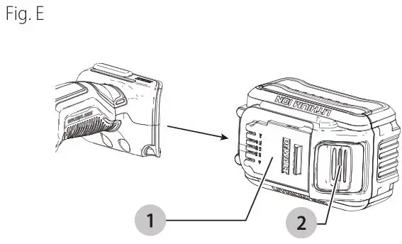
Installing and Removing the Battery Pack (Fig. E)
NOTE: For best results, make sure your battery pack is fully charged.
To install the battery pack 1 into the tool handle, align the battery pack with the rails inside the tool’s handle and slide it into the handle until the battery pack is firmly seated in the tool and ensure that it does not disengage.
To remove the battery pack from the tool, press the release button 2 and firmly pull the battery pack out of the tool handle. Insert it into the charger as described in the charger section of this manual

Proper Hand Position (Fig. F)
![]()
WARNING: To reduce the risk of serious personal injury, ALWAYS use proper hand position as shown.
![]()
WARNING: To reduce the risk of serious personal injury, ALWAYS hold securely in anticipation of a sudden reaction.
Proper hand position requires one hand on the main handle 20 and one hand on the auxiliary handle 7 or one hand on the main handle 20 and one hand on the bail handle 12

Variable Speed Trigger Switch (Fig. A)
These tools are equipped with a variable speed trigger switch that permits speed control from 0 to 2200 RPM. To turn the tool on, squeeze the variable speed trigger switch 5 shown in Figure A until the tool starts to run. The farther you depress the trigger, the faster it will operate.
Releasing the trigger turns the tool off.
Use lower speeds for applying compounds, and higher speeds for polishing. Use the highest speed (fully depress trigger) for buffing the car to a final lustre.
The tool can be locked on for continuous use by squeezing the trigger switch fully and depressing the lock button 11 shown in Figure A. Hold the lock button in as you gently release the trigger switch. The tool will continue to run. To turn the tool off from a locked-on position, squeeze and release the trigger switch once.
The variable speed trigger switch 5 has a no-volt release function. In the event of a dead battery or other unexpected shut down, the trigger switch needs to be cycled (depress the trigger switch, release, then depress again) to restart the tool.
Speed Control Wheel (Fig. A)
The maximum speed of your tool can be changed by rotating the speed control wheel 3 to the desired setting.
The wheel incorporates detents to prevent inadvertent wheel movement and to facilitate speed selection. For added versatility, the trigger switch may be locked in its full on position and tool speed changed by means of the speed control wheel 3 alone.
The electronic speed control not only lets you select the speed to suit the job, but also helps to maintain that speed as you load the tool by pressing down. It’s this feature, coupled with the variable speed trigger switch, that make this tool such a value.
The speed control wheel 3 can be set for any speed between 800 and 2200 RPM and the variable speed switch will then control tool speed from zero to the wheel setting.
For example: A control wheel setting of 2200 RPM will allow the variable speed switch to operate the tool between zero and 2200 RPM, depending on how far the trigger switch is depressed. A wheel setting of 800 RPM would allow the switch to operate the tool from zero to 800 RPM.
The electronic speed control feature comes into play whenever the trigger switch is fully depressed and the tool is running at the selected speed determined by the setting of the control wheel. As you load the tool by pushing it down on the work surface, (with the trigger fully depressed) the electronic circuit inside the tool will compensate for the loading and maintain the selected speed. If the speed selected by the control wheel is 2200 RPM, as in the example above, the tool will maintain 2200 RPM, as it is loaded.
It is important to remember two things about electronic speed control:
- The electronic speed control operates only when the variable speed trigger switch 5 is fully depressed.
- The effect of electronic speed control is much easier to observe at lower speed settings (1400 RPM and below), than at high speeds. As the tool approaches 2000 RPM, the effect is considerably less dramatic.
Keep in mind that, with a conventional polisher running at a typical no-load speed of 2200 RPM, the tool slows down to about 2000 RPM under a polishing load. Your polisher will continue to run at 2200 RPM (or any speed you select with the control wheel) as a load is applied. Since it doesn’t slow down, the speed may be greater than you’re used to, so some extra caution should be observed until you get the “feel” of your polisher. If you feel the speed is too great, you can, of course, slow the speed down with either the trigger switch or the control wheel.
Polishing (Fig. F)
These instructions and suggestions are intended to familiarize new operators in overall general operation of power polishing. You will develop your own techniques which will make the job easier and faster as you learn power polishing.
- You should use utmost care when power polishing around or over sharp objects and contours of the car body. It is very important to use the correct pressure while polishing various sections of an automobile body. For example, light pressure should be applied when
polishing over sharp edges of body panels, or over edges of the rain gutter along the top. - Since everyone does not use the same type of power polish, we recommend you clean and polish a test section on a flat area of the car first. From this test section, you can judge the strength or cleaning action of your power polish.
- Remember, all power polish is not the same. Different brands will react differently on various painted surfaces. Also, you are now using a rotary polisher with power polish which is entirely different from any hand application which you may have done before. Wash
the car before power polishing it. Washing will remove loose dirt, scum, road salt, etc. which could act as an abrasive and damage paint. Loose dirt, etc. will also clog the polishing pad and you will have to clean it more often. - Without turning the tool on, grasp the handles of the tool and pick it up (Fig. F). Keep the tool away from your body and depress the trigger switch. Make sure you have a firm grip on the handles and operate the tool freely without forced effort or unnecessary pressure. The side handle can be easily changed to either side of the tool for left-handed or right-handed operation.
NOTE: The high speed rubbing action of the polishing bonnet upon the surface of an automobile can build a static charge on the metal portions of this tool. This can result in a sensation of a very short mild electric shock when the metal area of the tool is touched, and will be more noticeable on days when the humidity is low. This is a harmless phenomenon but you are invited to bring the tool to a DeWALT service center where it can be checked to assure that no electrical malfunction is present.
MAINTENANCE
![]()
WARNING: To reduce the risk of serious personal injury, turn unit off and remove the battery pack before making any adjustments or removing/installing attachments or accessories. An accidental start-up can cause injury.
Cleaning
![]()
WARNING: Blow dirt and dust out of all air vents with clean, dry air at least once a week. To minimize the risk of eye injury, always wear ANSI Z87.1 approved eye protection when performing this procedure.
![]()
WARNING: Never use solvents or other harsh chemicals for cleaning the non-metallic parts of the tool. These chemicals may weaken the plastic materials used in these parts. Use a cloth dampened only with water and mild soap. Never let any liquid get inside the tool; never immerse any part of the tool into a liquid.
Accessories
WARNING: Since accessories, other than those offered by DeWALT, have not been tested with this product, use of such accessories with this tool could be hazardous. To reduce the risk of injury, only DeWALT recommended accessories should be used with this product.
Recommended accessories for use with your tool are available at extra cost from your local dealer or authorized service center. If you need assistance in locating any accessory, please contact DeWALT Industrial Tool Co., 701 East Joppa Road, Towson, MD 21286, call
1-800-4-D e WALT (1-800-433-9258) or visit our website: www.dewalt.com.
Use only accessories having a maximum operating speed at least as high as the highest “NO LOAD RPM” marked on the tool’s nameplate. This precaution applies to any accessory on any tool.
- Rubber backing pads: 7″ (180 mm) Quick Change Super Flexible Rubber Backing Pad (includes clamp washer)
- 7″ (180 mm) hook and loop backing pads
- soft rubber gear case cover
- Wool ingestion shields
- Auxiliary handle
- Bail handle
Repairs
The charger and battery pack are not serviceable. There are no serviceable parts inside the charger or battery pack.
![]() WARNING: To assure product SAFETY and RELIABILITY, repairs, maintenance and adjustment (including brush inspection and replacement, when applicable) should be performed by a DeWALT factory service center or a D e WALT authorized service center. Always use identical replacement parts.
WARNING: To assure product SAFETY and RELIABILITY, repairs, maintenance and adjustment (including brush inspection and replacement, when applicable) should be performed by a DeWALT factory service center or a D e WALT authorized service center. Always use identical replacement parts.
Register Online
Thank you for your purchase. Register your product now for:
- Warranty service: Registering your product will help you obtain more efficient warranty service in case there is a problem with your product.
- Confirmation OF Ownership: In case of an insurance loss, such as fire, flood or theft, your registration of ownership will serve as your proof of purchase.
- FOR YOUR SAFETY: Registering your product will allow us to contact you in the unlikely event a safety notification is required under the Federal Consumer Safety Act.
- Register online at www.dewalt.com
Three Year Limited Warranty
DeWALT will repair or replace, without charge, any defects due to faulty materials or workmanship for three years from the date of purchase (two years for batteries). This warranty does not cover part failure due to normal wear or tool abuse. For further detail of warranty coverage and warranty repair information, visit www.dewalt.com or call 1-800-4-D e WALT (1-800-433-9258). This warranty does not apply to accessories or damage caused where repairs have been made or attempted by others.
THIS LIMITED WARRANTY IS GIVEN IN LIEU OF ALL OTHERS, INCLUDING THE IMPLIED WARRANTY OF MERCHANTABILITY AND FITNESS FOR A PARTICULAR PURPOSE, AND EXCLUDES ALL INCIDENTAL OR CONSEQUENTIAL DAMAGES.
Some states do not allow limitations on how long an implied warranty lasts or the exclusion or limitation of incidental or consequential damages, so these limitations may not apply to you. This warranty gives you specific legal rights and you may have other rights which vary in certain states or provinces.
In addition to the warranty DeWALT tools are covered by our:
1 YEAR FREE SERVICE
DeWALT will maintain the tool and replace worn parts caused by normal use, for free, any time during the first year after purchase.
2 YEARS FREE service On DeWAlT BATTERY PACKS
DC9071, DC9091, DC9096, DC9182, DC9280, DC9360, DCB120, DCB122, DCB124, DCB127, DCB201, DCB203BT, DCB207, DCB361
3 YEARS FREE service On DeWAlT BATTERY PACKS
DCB200, DCB203, DCB204, DCB204BT, DCB205, DCB205BT, DCB206, DCB230, DCB606, DCB609, DCB612
NOTE: Battery warranty voided if the battery pack is tampered with in any way. DeWALT is not responsible for any injury caused by tampering and may prosecute warranty fraud to the fullest extent permitted by law.
90 DAY Money BACK guarantee
If you are not completely satisfied with the performance of your DeWALT Power Tool or Nailer for any reason, you can return it within 90 days from the date of purchase with a receipt for a full refund – no questions asked.
Latin America: This warranty does not apply to products sold in Latin America. For products sold in Latin America, see country specific warranty information contained in the packaging, call the local company or see website for warranty information.
FREE Warning label Replacement: If your warning labels become illegible or are missing, call 1-800-4-DeWALT (1-800-433-9258) for a free replacement.
Compatible battery packs and chargers

* Maximum initial battery voltage (measured without a workload) is 12, 20, 60 or 120 volts. Nominal voltage is 10.8, 18, 54 or 108. (120V Max* is based on using 2 D e WALT 60V Max* lithium-ion batteries combined.)
**BT – Bluetooth®
NOTE: The Bluetooth® word mark and logos are registered trademarks owned by the Bluetooth®, SIG, Inc. and any use of such marks by DeWALT is under license. Other trademarks and trade names are those of their respective owners.
DeWALT Industrial Tool Co. 701 East Joppa Road, Towson, MD 21286
Copyright © 2019
The following are trademarks for one or more D e WALT power tools: the yellow and black color scheme, the “D” shaped air intake grill, the array of pyramids on the handgrip, the kit box configuration, and the array of lozenge-shaped humps on the surface of the tool.