
DEWALT Telescopic Cutting and Miter Saw

CROSS-CUT MITRE SAW DWS771, DWS777


Congratulations!
You have chosen a DEWALT tool. Years of experience, thorough product development and innovation make DEWALT one of the most reliable partners for professional power tool users.
Technical Data
| DWS771 | DWS777 | ||
| Voltage | V | 230 | 230 |
| (U.K. & Ireland only) | V | 230 | 230/115 |
| Type | 1 | 1 | |
| XPS | Yes | Yes | |
| Power input | W | 1550 | 1800/1600 |
| Blade diameter | mm | 216 | 216 |
| Blade bore | mm | 30 | 30 |
| Max. blade speed | min–1 | 2600–5200 | 6300 |
| Mitre (max. positions) | left and right | 50° | 50° |
| Bevel (max. positions) | left | 48° | 48° |
| Compound mitre | bevel | 45° | 45° |
| mitre | 45° | 45° | |
| Capacities | |||
| cross-cut 90° | mm | 60 x 270 | 60 x 270 |
| mitre 45° | mm | 60 x 190 | 60 x 190 |
| mitre 48° | mm | 60 x 180 | 60 x 180 |
| bevel 45° | mm | 48 x 270 | 48 x 270 |
| bevel 48° | mm | 45 x 270 | 45 x 270 |
| Overall dimensions | mm | 460 x 560 x 430 | 460 x 560 x 430 |
| Weight | kg | 15.0 | 15.0 |
| Noise values and vibration values (triax vector sum) according to EN61029: | |||
| LPA (sound pressure) | dB(A) | 91 | 93 |
| LWA (acoustic power) | dB(A) | 102 | 104 |
| K (acoustic power uncertainty) | dB(A) | 3.2 | 3.9 |
| Vibration emission value ah | |||
| ah = | m/s² | 2.1 | 2.1 |
| Uncertainty K = | m/s² | 1.5 | 1.5 |
The vibration emission level given in this information sheet has been measured in accordance with a standardized test given in EN61029 and may be used to compare one tool with another. It may be used for a preliminary assessment of exposure.
WARNING: The declared vibration emission level represents the main applications of the tool. However if the tool is used for different applications, with different accessories or poorly maintained, the vibration emission may differ. This may significantly increase the exposure level over the total working period.
An estimation of the level of exposure to vibration should also take into account the times when the tool is switched off or when it is running but not actually doing the job. This may significantly reduce the exposure level over the total working period.
Identify additional safety measures to protect the operator from the effects of vibration such as: maintain the tool and the accessories, keep the hands warm, organisation of work patterns.
NOTE: This device is intended for the connection to a power supply system with maximum permissible system impedance Zmax of 0.28 Ohm at the interface point (power service box) of user’s supply.
The user has to ensure that this device is connected only to a power system which fulfils the requirement above. If necessary, the user can ask the public power supply company for the system impedance at the interface point.
Definitions: Safety Guidelines
The definitions below describe the level of severity for each signal word. Please read the manual and pay attention to these symbols.
- DANGER: Indicates an imminently hazardous situation which, if not avoided, will result in death or serious injury.
- WARNING: Indicates a potentially hazardous situation which, if not avoided, could result in death or serious injury.
- CAUTION: Indicates a potentially hazardous situation which, if not avoided, may result in minor or moderate injury.
- NOTICE: Indicates a practice not related to personal injury which, if not avoided, may result in property damage.
- Denotes risk of electric shock.
- Denotes risk of fire.
- Denotes sharp edges.
EC-Declaration of Conformity
Cross-cut Mitre Saw
DWS771, DWS777
DEWALT declares that these products described under Technical Data are in compliance with: 2006/42/EC, EN61029-1:2009 + A11:2010, EN61029-2-9:2012 + A11:2013.
These products also comply with Directive 2004/108/EC (until 19.04.2016), 2014/30/EU (from 20.04.2016) and 2011/65/EU. For more information, please contact DEWALT at the following address or refer to the back of the manual.
The undersigned is responsible for compilation of the technical file and makes this declaration on behalf of DEWALT.
Markus Rompel
Director Engineering
DEWALT, Richard-Klinger-Straße 11,
D-65510, Idstein, Germany
26.02.2016
Safety Instructions
WARNING! When using electric tools basic safety precautions should always be followed to reduce the risk of fire, electric shock and personal injury including the following. Read all these instructions before attempting to operate this product and save these instructions.
SAVE THIS MANUAL FOR FUTURE REFERENCE
General Safety Rules
- Keep work area clear.
Cluttered areas and benches invite injuries. - Consider work area environment.
Do not expose the tool to rain. Do not use the tool in damp or wet conditions. Keep the work area well lit (250–300 Lux). Do not use the tool where there is a risk of causing fire or explosion, e.g., in the presence of flammable liquids and gases. Work area should be well ventilated. - Guard against electric shock.
Avoid body contact with earthed surfaces (e.g., pipes, radiators, cookers and refrigerators). When using the tool under extreme conditions (e.g., high humidity, when metal swarf is being produced, etc.), electric safety can be improved by inserting an isolating transformer or a (FI) earth-leakage circuit-breaker. - Keep other persons away.
Do not let persons, especially children, not involved in the work, touch the tool or the extension cord and keep them away from
the work area. - Store idle tools.
When not in use, tools must be stored in a dry place and locked
up securely, out of reach of children. - Do not force the tool.
It will do the job better and safer at the rate to which it was intended. - Use the right tool.
Do not force small tools to do the job of a heavy duty tool. Do not use tools for purposes not intended; for example do not use circular saws to cut tree limbs or logs. - Dress properly.
Do not wear loose clothing or jewellery, as these can be caught in moving parts. Non-skid footwear is recommended when working outdoors. Wear protective hair covering to contain long hair. - Use protective equipment.
Always use safety glasses. Use a face or dust mask if working operations create dust or flying particles. If these particles might be considerably hot, also wear a heat-resistant apron. Wear ear protection at all times. Wear a safety helmet at all times. - Connect dust extraction equipment.
If devices are provided for the connection of dust extraction and collecting equipment, ensure these are connected and properly used. - Do not abuse the cord.
Never yank the cord to disconnect it from the socket. Keep the cord away from heat, oil and sharp edges. Never carry the tool by its cord. - Secure work.
Where possible use clamps or a vice to hold the work. It is safer than using your hand and it frees both hands to operate the tool. - Do not overreach.
Keep proper footing and balance at all times. - Maintain tools with care.
Keep cutting tools sharp and clean for better and safer performance. Follow instructions for lubricating and changing accessories. Inspect tools periodically and if damaged have them repaired by an authorized service facility. Keep handles
and switches dry, clean and free from oil and grease. - Disconnect tools.
When not in use, before servicing and when changing accessories such as blades, bits and cutters, disconnect tools from the power supply. - Remove adjusting keys and wrenches.
Form the habit of checking to see that adjusting keys and wrenches are removed from the tool before operating the tool. - Avoid unintentional starting.
Do not carry the tool with a finger on the switch. Be sure that the tool is in the “off” position before plugging in. - Use outdoor extension leads.
Before use, inspect the extension cable and replace if damaged. When the tool is used outdoors, use only extension cords intended for outdoor use and marked accordingly. - Stay alert.
Watch what you are doing. Use common sense. Do not operate the tool when you are tired or under the influence of drugs or alcohol. - Check for damaged parts.
Before use, carefully check the tool and mains cable to determine that it will operate properly and perform its intended function. Check for alignment of moving parts, binding of moving parts, breakage of parts, mounting and any other conditions that may affect its operation. A guard or other part that is damaged should be properly repaired or replaced by an authorized service centre unless otherwise indicated in this instruction manual. Have defective switches replaced by an authorized service centre.
Do not use the tool if the switch does not turn it on and off.
Never attempt any repairs yourself.
WARNING! The use of any accessory or attachment or performance of any operation with this tool other than those recommended in this instruction manual may present a risk of personal injury. - Have your tool repaired by a qualified person.
This electric tool complies relevant safety rules. Repairs should only be carried out by qualified persons using original spare parts; otherwise this may result in considerable danger to
the user.
Additional Safety Rules for Mitre Saws
- The machine is provided with a special configured power supply cord which can only be replaced by the manufacturer or its authorised service agent.
- Do not use the saw to cut other materials than those recommended by the manufacturer.
- Do not operate the machine without guards in position, or if guards do not function or are not maintained properly.
- Ensure that the arm is securely fixed when performing bevel cuts.
- Keep the floor area around the machine level, well-maintained and free of loose materials, e. g., chips and cut-offs.
- Select the correct blade for the material to be cut.
- Use correctly sharpened saw blades. Observe the maximum speed mark on the saw blade.
- Make sure all locking knobs and clamp handles are tight before starting any operation.
- Never place either hand in the blade area when the saw is connected to the electrical power source.
- Never attempt to stop a machine in motion rapidly by jamming a tool or other means against the blade; serious accidents can occur.
- Before using any accessory consult the instruction manual.
The improper use of an accessory can cause damage. - Use a holder or wear gloves when handling a saw blade or rough material.
- Ensure that the saw blade is mounted correctly before use.
- Make sure that the blade rotates in the correct direction.
- Do not use blades of larger or smaller diameter than recommended. For the proper blade rating refer to the technical data. Use only the blades specified in this manual, complying with EN847-1.
- Consider applying specially designed noise-reduction blades.
- Do not use HIGH SPEED STEEL blades.
- Do not use cracked or damaged saw blades.
- Do not use any abrasive or diamond discs.
- Use only saw blades where the marked speed is at least equal to the speed marked on the saw.
- Never use your saw without the kerf plate.
- Raise the blade from the kerf in the workpiece prior to releasing the switch.
- Before each cut ensure that the machine is stable.
- Do not wedge anything against the fan to hold the motor shaft.
- The blade guard on your saw will automatically raise when the arm is brought down; it will lower over the blade when head lock up release lever 2 is pushed.
- Never raise the blade guard manually unless the saw is switched off. The guard can be raised by hand when installing or removing saw blades or for inspection of the saw.
- Check periodically that the motor air slots are clean and free of chips.
- Replace the kerf plate when worn.
- Disconnect the machine from the mains before carrying out any maintenance work or when changing the blade.
- Never perform any cleaning or maintenance work when the machine is still running and the head is not in the rest position.
- When fitted with LED, no exchange with different type of LED permitted. Repairs shall only be carried out by the manufacturer or an authorized agent.
- Connect the saw to a dust collection device when sawing wood. Always consider factors which influence exposure of dust such as:
- type of material to be machined (chip board produces more dust than wood);
- sharpness of the saw blade;
- correct adjustment of the saw blade,
- dust extractor with air velocity not less than 20 m/s.
- Ensure that the local extraction as well as hoods, baffles and chutes are properly adjusted.
- Please be aware of the following factors influencing exposure to noise:
- use saw blades designed to reduce the emitted noise;
- use only well sharpened saw blades;
- Machine maintenance shall be conducted periodically;
- Provide adequate general or localized lighting;
- Ensure the operator is adequately trained in the use, adjustment and operation of the machine;
- Ensure that any spacers and spindle rings are suitable for the purpose as stated in this manual.
- Refrain from removing any cut-offs or other parts of the workpiece from the cutting area while the machine is running and the saw head is not in the rest position
- Never cut workpieces shorter than 150 mm.
- Without additional support the machine is designed to accept the maximum workpiece size of:
- Height 60 mm by width 270 mm by length 500 mm
- Longer workpieces need to be supported by suitable additional table, e.g. DE7023. Always clamp the workpiece safely.
- In case of an accident or machine failure, immediately turn the machine off and disconnect machine from the power source.
- Report the failure and mark the machine in suitable form to prevent other people from using the defective machine.
- When the saw blade is blocked due to abnormal feed force during cutting, turn the machine off and disconnect it from power supply. Remove the workpiece and ensure that the saw blade runs free. Turn the machine on and start new cutting operation with reduced feed force.
- Never cut light alloy, especially magnesium.
- Whenever the situation allows, mount the machine to a bench using bolts with a diameter of 8 mm and 80 mm in length.
Residual Risks
The following risks are inherent to the use of saws:
- In spite of the application of the relevant safety regulations and the implementation of safety devices, certain residual risks cannot be avoided. These are:
- injuries caused by touching the rotating parts Impairment of hearing.
- Risk of accidents caused by the uncovered parts of the rotating saw blade.
- Risk of injury when changing the unprotected saw blade.
- Risk of squeezing fingers when opening the guards.
- Health hazards caused by breathing dust developed when sawing wood, especially oak, beech and MDF.
The following factors increases the risk of breathing problems:
- No dust extractor connected when sawing wood
- Insufficient dust extraction caused by uncleaned exhaust filters
Package Contents
The package contains:
- Partly assembled machine
- 2 Hex key 4/6 mm
- 216 mm TCT saw blade
- 1 Material clamp
- Instruction manual
- Check for damage to the tool, parts or accessories which may have occurred during transport.
- Take the time to thoroughly read and understand this manual prior to operation.
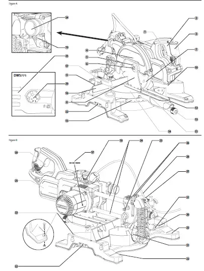
Description (Fig. A, B, G, H)
WARNING: Never modify the power tool or any part of it. Damage or personal injury could result.
- On/off switch
- Guard lock up release lever
- Carrying handle
- Fixed upper guard
- Outer flange
- Blade bolt
- Lower blade guard
- Saw blade
- Sliding fence lock knob
- Fixed table
- kerf plate
- Mitre arm
- Mitre latch
- Rotating table/mitre arm
- Mitre scale
- Sliding fence
- Material clamp
- Traverse lock
- Guard lock up hook
- Bevel clamp handle
- Bevel scale
- Bench mounting holes
- Lock down button
- Traverse bars
- Saw head
- Hex keys (Fig. G)
- Cable clamp
- Cable
- Speed control dial (DWS771 only)
- Padlock hole
- Override button
- Carrying handle (left and right)
- Inner flange (Fig. H)
- Dust extraction nozzle
Optional accessories (Fig. A, C–E, K) - Table end plate
- Support guide rails
- Material support plate
- Swivelling stop
- Adjustable stand 760 mm (max. height)
- Legstand
- Length stop for short workpieces
- Roller table
- Twist-lock quick connector
Intended Use
Your DEWALT Cross-Cut Mitre Saw has been designed for professional cutting wood, wood products and plastics. It performs the sawing operations of cross-cutting, bevelling and mitring easily, accurately and safely.
This unit is designed for use with a nominal blade diameter 216 mm carbide tip blade. DO NOT use under wet conditions or in presence of flammable liquids or gases.
These miter saws are professional power tools.
DO NOT let children come into contact with the tool. Supervision is required when inexperienced operators use this tool.
WARNING! Do not use the machine for purposes other than intended.
This product is not intended for use by persons (including children) suffering from diminished physical, sensory or mental abilities; lack of experience, knowledge or skills unless they are supervised by a person responsible for their safety. Children should never be left alone with this product.
Electrical Safety
The electric motor has been designed for one voltage only. Always check that the power supply corresponds to the voltage on the rating plate.
Your tool is double insulated in accordance with EN61029; therefore no earth wire is required.
In case of cord replacement the tool must only be repaired by an authorized service agent or by qualified electrician.
The following cords are mandatory:
DW770 / DW770GP: H05RN-F, 2×1.0 mm²
DW770 LX / DW770GP LX: H05RR-F, 2×1.5 mm²
DWS777 / DWS771: H05RN-F, 2×1.0 mm²
DWS777 LX / DWS771 LX: H05RR-F, 2×1.5 mm²
Mains Plug Replacement
(U.K. & Ireland Only)
If a new mains plug needs to be fitted:
- Safely dispose of the old plug.
- Connect the brown lead to the live terminal in the plug.
- Connect the blue lead to the neutral terminal.
WARNING: No connection is to be made to the earth terminal.
Follow the fitting instructions supplied with good quality plugs. Recommended fuse: 13 A.
WARNING: To reduce the risk of injury, turn unit off and disconnect machine from power source before installing and removing accessories, before adjusting or changing set-ups or when making repairs. Be sure the trigger switch is in the OFF position. An accidental
start-up can cause injury.
The attention of UK users is drawn to the “woodworking machines regulations 1974” and any subsequent amendments.
Ensure the machine is placed to satisfy your ergonomic conditions in terms of table height and stability. The machine site shall be chosen so that the operator has a good overview and enough free surrounding space around the machine that allows handling of the workpiece without any restrictions.
To reduce effects of increased vibration, make sure the environment is not too cold, the machine and accessory are well maintained and the workpiece size is suitable for this machine.
Switching On and Off (Fig. A)
A hole 30 is provided in the on/off switch 1 for insertion of a padlock to lock the tool.
- To run the tool, press the on/off switch 1 .
- To stop the tool, release the switch.
Use of XPS™ LED Worklight System (Fig. A, V)
NOTE: The mitre saw must be connected to a power source.
The XPS™ LED Worklight System is operated with an push button switch, fitted on the handle under the black plastic lever. The XPS™ LED Worklight System is independent of the mitre saw’s trigger switch.
To cut through an existing pencil line on a piece of wood:
- Push the black plastic lever, then pull down on the operating handle 3 to bring the saw blade 8 close to the wood. The shadow of the blade will appear on the wood.
- Align the pencil line with the edge of the blade’s shadow. You may have to adjust the mitre or bevel angles in order to match the pencil line exactly.
Speed Control Dial (DWS771 only)
The speed control dial 29 can be used for advance setting of the required range of speed. Turn the speed control dial 29 to the desired range, which is indicated by a number (1–5).
- Use high speeds for sawing soft materials such as wood.
- Use low speeds for sawing hardwood.
Body and Hand Position
Proper positioning of your body and hands when operating the mitre saw will make cutting easier, more accurate and safer.
WARNING:
- Never place your hands near the cutting area.
- Place your hands no closer than 150 mm from the blade.
- Hold the workpiece tightly to the table and the fence when cutting. Keep your hands in position until the switch has been released and the blade has completely stopped.
- Always make dry runs (without power) before finish cuts so that you can check the path of the blade.
- Do not cross your hands.
- Keep both feet firmly on the floor and maintain proper balance.
- As you move the saw arm left and right, follow it and stand slightly to the side of the saw blade.
Basic Saw Cuts
Vertical straight cross cut (Fig. A, S)
NOTE: Use 216 mm saw blades with 30 mm arbor holes to obtain the desired cutting capacities.
- Slacken the mitre latch 13 and subsequently lift it up.
- Engage the mitre latch 13 at the 0° position and fasten the mitre latch.
- Place the wood to be cut against the fence 16 .
- Take hold of the carrying handle 3 and press the guard lock up release lever 2 to release the guard. Press the trigger switch 1 to start the motor. It is recommended to start the cut near the fence.
- Depress the head to allow the blade to cut through the timber and enter the plastic
kerf plate 11 . - When the head is fully depressed, slowly pull it across to complete the cut.
- After completing the cut, release the switch and wait for the saw blade to come to a complete standstill before returning the head to its upper rest position.
WARNING:
- For some types of plastic profiles, it is advisable to follow the sequence in reverse order.
- The lower blade guard is designed to close quickly when the lever 2 is released. If it does not close within 1 second, have the saw serviced by an authorized DEWALT repair agent.
Vertical mitre cross-cut (Fig. A, T)
- Squeeze the mitre latch 13 . Move the arm left or right to the required angle.
- The mitre latch will automatically locate at 0°, 15°, 22.5°, 31.62°, 45° and 50° both left and right. If any intermediate angle is required hold the head firmly and lock by fastening the mitre latch.
- Always ensure that the mitre lock lever is locked tightly before cutting.
- Proceed as for a vertical straight cross-cut.
WARNING: When mitring the end of a piece of wood
with a small off-cut, position the wood to ensure that the off-cut is to the side of the blade with the greater angle to the fence, i.e.:
- left mitre, off-cut to the right
- right mitre, off-cut to the left
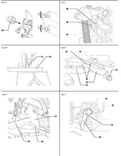
Bevel cross-cuts (Fig. P, U)
Bevel angles can be set from 0° to 48° to the left. Bevels up to 45° can be cut with the mitre arm set between zero and a maximum of 45° mitre position right or left.
- Loosen the bevel clamp handle 20 and set the bevel as desired.
- Set the override button 31 if required.
- Hold the head firmly and do not allow it to fall.
- Tighten the bevel clamp handle 20 firmly.
- Proceed as for a vertical straight cross-cut.
Quality of Cut
The smoothness of any cut depends on a number of variables, i.e. the material being cut. When smoothest cuts are desired for moulding andother precision work, a sharp (60-tooth carbide) blade and a slower, even cutting rate will produce the desired results.
WARNING: Ensure that the material does not creep while cutting; clamp it securely in place. Always let the blade come to a full stop before raising the arm. If small fibres of wood still split out at the rear of the workpiece, stick a piece of masking tape on the wood where the cut will be made. Saw through the tape and carefully remove tape when finished.
Clamping the Workpiece (Fig. C, X)
WARNING: Always use a material clamp.
For best results use the material clamp 17 made for use with your saw. To Install clamp
- Insert it into the hole behind the fence. The clamp 17 should be facing toward the back of the mitre saw. Ensure the groove on the clamp rod is fully inserted into the base of the mitre saw. If the groove is visible, the clamp will not be secure.
- Rotate the clamp 180º toward the front of the mitre saw.
- Loosen the knob to adjust the clamp up or down, then use the fine adjust knob to firmly clamp the workpiece.
NOTE: Place the clamp on the right side of the base when beveling. ALWAYS MAKE DRY RUNS (UNPOWERED) BEFORE FINISH CUTS TO CHECK THE PATH OF THE BLADE. ENSURE THE CLAMP DOES NOT INTERFERE WITH THE ACTION OF THE SAW OR GUARDS.
Compound Mitre (Fig. W)
This cut is a combination of a mitre and a bevel cut. This is the type of cut used to make frames or boxes with slanting sides like the one shown in figure W.
WARNING: If the cutting angle varies from cut to cut, check that the bevel clamp handle and the mitre clamping knob are securely tightened. These must be tightened after making any changes in bevel or mitre.
- The chart shown below will assist you in selecting the proper bevel and mitre settings for common compound mitre cuts.
- To use the chart, select the desired angle “A” (Fig. W) of your project and locate that angle on the appropriate arc in the chart. From that point follow the chart straight down to find the correct bevel angle and straight across to find the correct mitre angle.

- Set your saw to the prescribed angles and make a few trial cuts.
- Practice fitting the cut pieces together.
Example: To make a four-sided box with 25° exterior angles (angle “A”) (Fig. W), use the upper right arc. Find 25° on the arc scale. Follow the horizontal intersecting line to either side to get the mitre angle setting on the saw (23°). Likewise follow the vertical intersecting line to the top or bottom to get the bevel angle setting on the saw (40°).
Always try cuts on a few scrap pieces of wood to verify the settings on the saw.
WARNING: Never exceed the compound mitre limits of 45° bevel with 45° left or right mitre.
Support for Short and Long Pieces (Fig. C, D)
Cutting Short Material
It is advisable to use the length stop 41 for short workpieces both for batch sawing and for short individual workpieces of different lengths. The length stop can only be used in conjunction with a pair of optional guide rails 35 .
Cutting Large Material
WARNING: To reduce the risk of injury, always support long workpieces.
Figure C shows the ideal configuration for sawing long workpieces when the saw is used free-standing (all items available as an option).
These items (except the legstand and the material clamp) are required both on the infeed and the outfeed side:
- Legstand 40 (supplied with mounting instructions).
- Guide rails (500 or 1,000 mm) 35 .
- Stands 39 to support the guide rails. Do not use the stands to support the machine! The height of the stands is adjustable.
- Material support plates 36 .
- Table end plate 34 for supporting the rails (also when working on an existing bench).
- Material clamp 17 .
- Swivelling stop 38 .
- Place your saw on the legstand and fit the guide rails.
- Firmly screw the material support plates 36 to the guide rails 35 .
- The material clamp 17 now functions as a length stop.
- Install the table end plates 34 .
- Install the swivelling stop 38 to the rear rail.
- Use the swivelling stop 38 to adjust the length of medium and long workpieces. It can be adjusted sideways or swung out of the way when not in use.
Dust Extraction (Fig. A, K)
WARNING: Whenever possible, connect a dust extraction device designed in accordance with the relevant regulations regarding dust emission.
Connect a dust collection device designed in accordance with the relevant regulations. The air velocity of externally connected systems shall be 20m/s +/- 2 m/s. Velocity to be measured in the connection tube at the point of connection, with the tool connected but not running. NOTE: The DWV9000 twist-lock quick connector 43 is recommended as an optional accessory to connect to the dust extraction device.
Observe the relevant regulations in your country for the materials to be worked.
The vacuum cleaner must be suitable for the material being worked.
When vacuuming dry dust that is especially detrimental to health or carcinogenic, use a special vacuum cleaner.
Transporting (Fig. A, B)
WARNING: In order to conveniently carry the mitre saw, the base is provided with two hand indentations 32 . Never use guards to lift or transport the mitre saw.
- To transport the saw, set the bevel and mitre positions to 0°.
- Press the lower guard lock up release lever 2 (Fig. A).
- Press the head down and press the lock down button 23 (Fig. B).
- Bring the saw blade to rest position and press the traverse lock 18 .
MAINTENANCE
Your DEWALT power tool has been designed to operate over a long period of time with a minimum of maintenance. Continuous satisfactory operation depends upon proper tool care and regular cleaning.
WARNING: To reduce the risk of injury, turn unit off and disconnect machine from power source before installing and removing accessories, before adjusting or changing set-ups or when making repairs. Be sure the trigger switch is in the OFF position. An accidental start-up can cause injury.
WARNING: If the saw blade is worn replace it with a new sharp blade.
Lubrication
Your power tool requires no additional lubrication.
Cleaning
Before use, carefully check the upper blade guard, movable lower blade guard as well as the dust extraction tube to determine that it will operate properly. Ensure that chips, dust or workpiece particle cannot lead to blockage of one of the functions.
In case of workpiece fragments jammed between saw blade and guards disconnect the machine from the power supply and follow the instructions given in section Mounting the saw blade. Remove the jammed parts and reassembling the saw blade.
- WARNING: Blow dirt and dust out of the main housing with dry air as often as dirt is seen collecting in and around the air vents. Wear approved eye protection and approved dust mask when performing this procedure.
- WARNING: Never use solvents or other harsh chemicals for cleaning the non-metallic parts of the tool. These chemicals may weaken the materials used in these parts. Use a cloth dampened only with water and mild soap. Never let any liquid get inside the tool; never immerse any part of the tool into a liquid.
- WARNING: To reduce the risk of injury, regularly clean the table top.
- WARNING: To reduce the risk of injury, regularly clean the dust collection system.
Optional Accessories
WARNING: Since accessories, other than those offered by DEWALT, have not been tested with this product, use of such accessories with this tool could be hazardous. To reduce the risk of injury, only DEWALT, recommended accessories should be used with this product.
Using the Roller Table (Fig. C–E)
The roller table 42 makes the handling of large and long pieces of wood very easy (Fig. E). It can be connected either to the left or to the right of the machine. The roller table requires the use of the optional legstand (Fig. C).
WARNING: Assemble the roller table following the instructions supplied with the legstand.
- Replace the short support bars provided with the legstand with the irregular rails from the table on the side the table is to be used.
- Follow all instructions provided with the roller table.
Range of saw blades available (recommended blades)
| Type of blade | Blade dimensions (diameter x bore x no. of teeth) | Usage |
| DT4310 series 40 | 216x30x24 | For general purpose, ripping and cross-cutting of wood and plastics |
| DT4286 series 40 | 216x30x80 | TCG for use with aluminum |
| DT4320 series 60 | 216x30x48 | ATB for fine cutting of manmade and natural wood |
| DT4350 series 60 | 216x30x60 | TCG for extra fine cutting of manmade and natural wood |
Consult your dealer for further information on the appropriate accessories.
Protecting the Environment
Separate collection. Products and batteries marked with this symbol must not be disposed of with normal household waste.
Products and batteries contain materials that can be recovered or recycled reducing the demand for raw materials. Please recycle electrical products and batteries according to local provisions. Further information is available at www.2helpU.com.