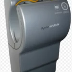
Dyson AB14 Airblade hand dryers
IMPORTANT SAFETY INSTRUCTIONS
WARNING
All electrical installation and repair work should be carried out by a qualified electrician or Dyson Service Engineer in accordance with current local codes or regulations. Risk of electric shock! If the casing is removed or handled improperly the internal components of the unit may cause harm or become permanently damaged. The unit is designed for dry, internal location only.
TO REDUCE THE RISK OF FIRE, ELECTRIC SHOCK, OR INJURY TO PERSONS, OBSERVE THE FOLLOWING:
Wiring
- Check that the electrical supply corresponds to that shown on the rating plate. If the product is connected to any electrical supply other than that stated on the rating plate permanent damage or improper/unsafe operation of the product may result.
- The product must be earthed.
- A means of all –pole disconnection must be incorporated into the fixed wiring, this and all wiring to the product must comply with all federal, state and local laws and applicable regulations, codes, and standards, including fire-rated construction.
Safety
- Use of protective equipment is recommended during the installation.
- Isolate the power before installation or service.
Installation
- Make sure that the unit is installed in compliance with all building codes and/or regulations.
- The unit must be mounted on a flat vertical wall capable of supporting the weight of the unit.
- Ensure no pipework (gas, water, air) or electrical cables, wires or ductwork are located directly behind the drilling/mounting area.
- To avoid contact with water from the user’s hands, do not install the unit above any electrical equipment.
DO NOT USE ANY JETWASH EQUIPMENT FOR CLEANING ON OR NEAR THIS UNIT
LOCATION
- Consult local and national accessibility codes and regulations for relevant installation guidelines. Conformity and compliance are the responsibility of the installer.
- If you are installing this hand dryer in a food handling or food manufacturing environment, please contact the Dyson Helpline for the specialist installation guide that supports this.
Important
- Please refer to the Dyson Owners Manual for details of the guarantee.
Fixings
To install this unit you will need (5) screws, toggle or masonry bolts and appropriate fittings for the wall type and weight of the unit (recommended minimum size of 7mm).
Remove fascia.
CAUTION: The fascia may have sharp edges.
- Remove the (6) tamper-proof screws from the unit with the service tool provided. Store the screws and mounting nuts safely.
- Remove the fascia as shown.
Selecting the height.
- Allow at least 200mm clearance under the unit.
- Recommended heights are shown, but may need to be adjusted for each individual installation.
- 990mm adult male height.
- 915mm adult female height.
- 815mm child/wheelchair user height UK.
- 840mm child/wheelchair user height ANZ.
Mount bracket to wall
Secure the bracket to the wall using appropriate fixings for the wall type and the weight of the main unit. Ensure the bracket is level.
Cable entry – rear/base.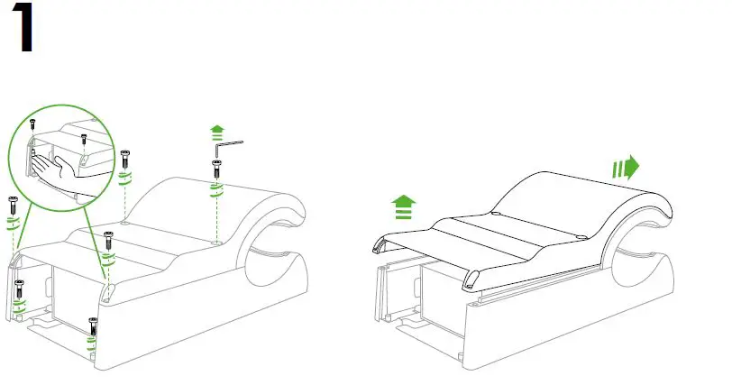
The options for cable entry are from the rear, base, or either side.
- OPTION A: Cable entry into the rear of the unit. Only pry out one knockout from the backplate. The cable route is directly from the wall into the unit.
- OPTION B: Cable entry from the base of the unit. Ensure the cable is not trapped between the backplate and the wall.
Cable entry – side.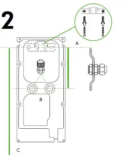
OPTION C: Cable entry from the side.
IMPORTANT: The unit is designed to have ONLY ONE side cable entry point, left or right.
- Ensure you work only on the side you have chosen for the cable entry point.
- Drill a 20mm diameter cable entry hole through the thin-wall section as illustrated.
Secure product to wall
- Hook the product on to the wall bracket. Mark the 3 fixing points, remove the product and drill the 3 holes.
NOTE: For easier access to the lower fixing screw, temporarily remove the filter. - Hook the backplate onto the wall bracket.
- Install the electrical cable.
- Secure the backplate to the wall.
- Replace the filter.
Electrical Connection
WARNING: Risk of electric shock
- Secure the live, neutral and earth wires into the correct terminal block locations.
- To avoid damage to the fascia, if entry is from the left-hand point in the backplate, ensure the cable is secured in front of the duct with the cable clip.
Attach fascia
- Replace the fascia as illustrated.
- Make sure that the clips on the top of the fascia are seated correctly.
- Insert and tighten the (2) anti-tamper screws into the middle of the fascia as illustrated.
- Insert and tighten the anti-tamper screws in the order shown ensuring the nuts in drawing 4 are installed.
- Test the unit for correct operation before affixing the (2) fascia caps.
NOTE: Do not use a sealant when fixing the unit to the wall.