![]()
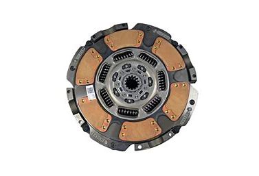
![]() Eaton 15.5″ Heavy-Duty Self-Adjusting Clutch CLMT1279 EN-US
Eaton 15.5″ Heavy-Duty Self-Adjusting Clutch CLMT1279 EN-US
May 2017
Installation Procedure
Measure
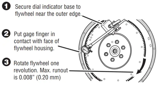
Measure Engine Flywheel Housing and Flywheel
Engine flywheel housing and flywheel must meet these specifications or it may result in premature clutch failure. Remove and replace old pilot bearing per engine manufacturer instructions. All gauge contact surfaces must be clean and dry. Clean flywheel surfaces of all grease, oil, and rust preventatives. Failure to perform this function can affect the performance of the clutch. Use a dial indicator and check the following:
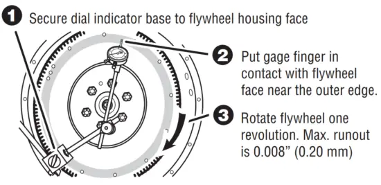
Flywheel Face Runout
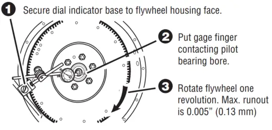
Pilot Bearing Bore Runout
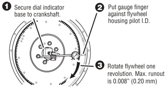
Flywheel Housing I.D. Runout
Flywheel Housing Face Runout
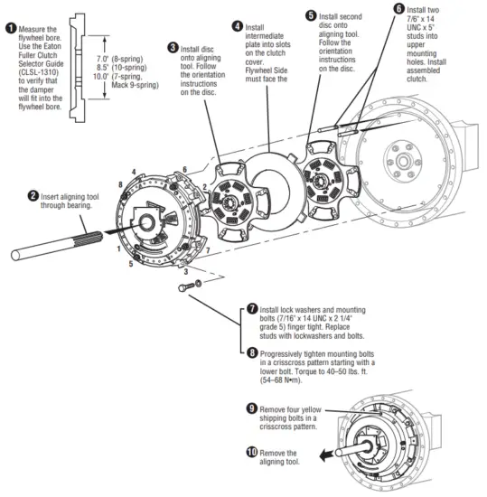
Install Clutch to Flywheel
NOTICE: Use the Eaton Fuller Clutch Selector Guide (CLSL1310) to make sure you have the right clutch!
![]() CAUTION: An assembled clutch weighs about 150 lbs. (68 kg).
CAUTION: An assembled clutch weighs about 150 lbs. (68 kg).
Avoid the risk of injury. Use proper equipment when lifting a clutch.
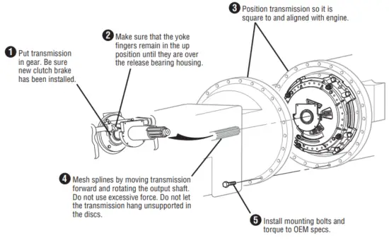
Install Transmission
Check Transmission For Wear
Replace any worn components.
![]()
Fasten Transmission To Flywheel Housing
Transmission installation and clutch set-up procedures are the same for the Solo and Solo XL.
![]() CAUTION: Do not pull on the release arm to install a transmission.
CAUTION: Do not pull on the release arm to install a transmission.
This will cause the clutch to over-adjust.
Set-up and Lubricate
Adjust Clutch Linkage
- Hydraulic Linkages:
Skip to Step 2.
Mechanical Linkages Only:
Adjust the clutch linkage until the yoke fingers contact the release bearing (zero free-play in the cab).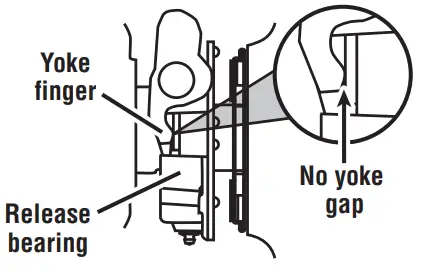
- Press the pedal to the floor up to 5 times, this:
• Moves release bearing slightly closer to the transmission
• Gains free play in the cab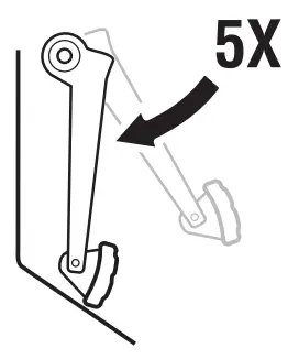
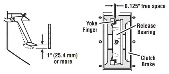
- With the pedal up, measure the distance between the release bearing and the clutch brake. The correct distance should be 0.490″ – .560″ (12.70 –14.22 mm):
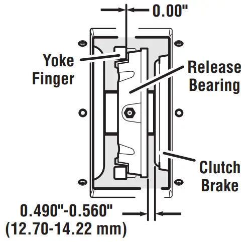 • If the distance is more than 0.560″ (14.22 mm) return to Step 1 and readjust the clutch linkage.
• If the distance is less than 0.490″ (12.70 mm) consult Heavy-Duty Clutch Service Manual (CLSM0200).
Verify Clutch Brake Squeeze - Have an assistant Insert a 0.010″ (0.25 mm) feeler gauge between the release bearing and the clutch brake.
Press the pedal down to clamp the gauge.
• If the gauge does not clamp, return to Step 1 and readjust the clutch linkage.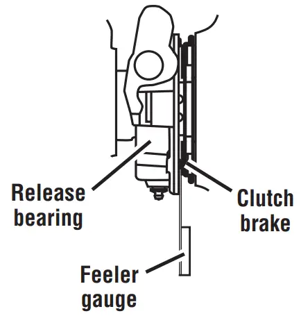
- Slowly let up on the pedal and check the pedal position at the moment the gauge can be removed.
• If the pedal is more than 1″ (25.4 mm) from the floor, readjust the truck linkage to move the yoke fingers further from the release bearing.
Return to Step 4.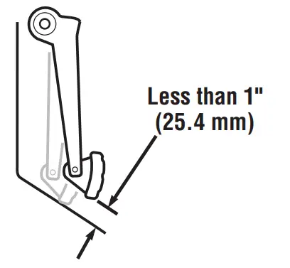 Verify Free-Play
Mechanical Linkages Only
Hydraulic Linkages: Skip to Step 7 - Verify there is 1 inch or more clutch pedal free-play with 0.125″ clearance between the release yoke finger and release bearing. If not, adjust clutch linkage per OEM instructions.
NOTICE: Do not reset the clutch.
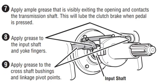
Lubricate
NOTICE: Eaton recommends the use of Roadranger EP2 for the release bearing lubrication or an equivalent Lithium Complex NLGI #2 or #3 grease with an NLGI LB/GC performance rating and a dropping point temperature of 220 ºC (428 or higher).
Failure to use the proper grease may affect bearing life and void the warranty coverage on your Eaton product. Refer to CLSM0200 Heavy-Duty Clutch Service Manual or TCMT0021 Lubrication Manual for grease intervals.
NOTICE: Do not add lube (never seize or grease) to the input shaft splines. The discs must be free to move.
Note: Refer to CLSM0200 for lube hose installation procedures used with hydraulic clutch release systems.
Note: Refer to CLSM0200 for clutch removal procedures.
Shipping bolts must be used to properly remove the clutch.
Eaton
Vehicle Group
P.O. Box 4013
Kalamazoo, MI 49003 USA 800-826-HELP (4357)
www.eaton.com/roadranger
Copyright Eaton, 2017.
Printed in the USA