FrSky 2.4GHz ACCST G-RX8 User Manual
Introduction
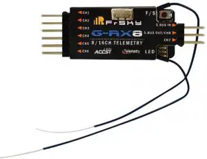
Thank you for purchasing FrSky G-RXB 8116th telemetry receiver. In order to fully enjoy the benefits of this system, please read the instruction manual carefully and set up the device as described below.
Overview
Specifications
- Dimension: 56.26mmx17mmx8mm (L • W • H)
- Weight: 5.89
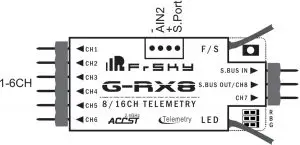
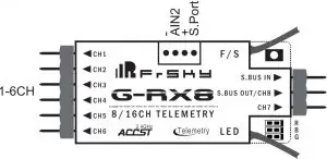
- Number of Channels: 16CH (1-8ch/9-16ch from conventional channel outputs, 1-16th from SBUS port or combine two receivers to become a 16 channels receiver with G-RX8,RX8R,X8R).
- Operating Voltage Range: 4.0-WV
- Operating Current: 100mA@5V
- Operating Range: full range
- Firmware Upgradable
- Compatibility: D16 mode
Features
- Variometer sensor: the measures is -700m-10000m with o.1m(lugh precision version) .support altimeter(the rate formula Is 1-16.7m/s).
- GRXB supports the redundancy function for the master and slave receivers. The master receiver receives SBUS signal from the slave receiver. The master receiver must be GRX8, and the slave receiver can be any brand receiver with SBUS output (for example, FrSky X8R. X6R. X4RSB. XSR, XM. XM+, G-RX8. L9R, etc)
Note: make sure telemetry Is disabled on the slave receiver when the slave receiver Is FrSky X series receiver. XM+ is recommended as the slave receiver.
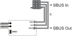
Both the master and the slave receiver signal from radio / transmitter module. The PWM outputs from the stronger signal port. Smart Port (S. Port) is a signal wire full duplex digital transmission interface developed by FrSky Electronic Co., Ltd. All products enabled with Smart Port (including XJT module, RX8R receiver, new hub-less sensors, new Smart Dashboard, etc), serial port user data and other user input/output devices can be connected without limitations for numbers or sequences at a high transmis-sion speed.
Binding Procedure
Binding is the process of uniquely associating a particular receiver to a transmitter/transmitter module. A transmitter/transmitter module can be bound to multiple receivers (not to be used simultaneously).A receiver can only be bound to one transmitter/transmitter module. Follow the steps below to finish the binding procedure.
- Put the transmitter/transmitter module into binding mode
- For Taranis X9D/X9D Plus/X9E and Taranis Q X7, turn on the transmitter, go to the MENU — MODEL SETUP — PAGE 2, choose Internal or External RF, and select BIND.
- For Horus X12S, turn on the transmitter, go to the RF SYSTEM, choose Internal or External RF, and select BIND under STATE.
- For transmitter module (XJT as an example), turn on the transmitter while holding the FS button on the module, release the button and the RED LED on XJT module flash.
- Connect the battery to the receiver while holding the F/S button on the receiver. The RED LED on the receiver will flash, indicating the binding process is completed.
- Turn off both the transmitter and the receiver.
- Turn on the transmitter and connect the battery. The GREEN LED on the receiver indicates the receiver is receiving commands from the transmitter. The receiver/transmitter module binding will not have to be repeated, unless one of the two is replaced.
Note: After binding procedure is completed, recycle the power and check if the receiver is really under control by linked transmitter.
When combine two receivers to become a 16CH receiver, you need to disable telemetry on either one of the two receiver’s. How to switch SBUS / PWM mode
- Turn on the receiver, if the BLUE LED on the receiver lights , the receiver stays in SBUS mode Otherwise, it stays in the PWM mode.
- Connect CH1 and CH2 by the jumper before Binding, the receiver will stay in PWM mode. The receiver will enter into SBUS mode without jumper connecting.
Note:
- SBUS Mode : CH1—CH6 output high precision PWM signal (Error < 0.5 us) , SBUS IN is used for redundancy function &CH8 outputs SBUS signal &CH7 no outputs.
- PWM Mode : CH1—CH4 output high precision PWM signal (Error < 0.5 us) , CH5—CH8 output ordinary precision, SBUS IN / SBUS OUT will be disabled.
How to Disable/Enable altimeter function
- The factory default setting is “enabled”.
- in case you want to disable altimeter functionality bring the receiver into normal operational mode , hold the F/S button to bind > 3 s, the BLUE LED will flash 3 times, then switch successfully and the function will be disabled. (If you want to enable the function, just repeat steps will be okay).
How to switch the output 1 — 8/9 — 16CH
- The receiver default output 1 — 6 CH (or 8CH),If the user uses the X12S, you need to choose corresponding operations when the remote control to bind. If user uses X7 / X9, you need to connect CH3 and CH4 by the jumper , and then perform binding process , after the successful binding , output channel change successfully. If outputs 9 — 16CH, and user needs to change back to 1 — 8CH, follow the same operation.
Failsafe
Failsafe is a useful feature in which all controls move to a preset position whenever the control signal is lost for a period of time. G-RX8 supports failsafe function for all channels. Follow the steps below to set failsafe positions for each channel:
- Bind the receiver first and turn on both the transmitter and the receiver;
- Move the controls to the desired failsafe position for all channels; 3. Press briefly the F/S button on the receiver (less than 1 second). The Green LED will flash twice, indicating the failsafe position has been set in the receiver.
To disable the failsafe function, re-bind the receiver. Failsafe is recommended to set when system is firstly used, or receiver has been re-bound. Follow steps below to set failsafe.
Option-1:
How to set failsafe to a user-determined state on lost signal:
- Bind the receiver to the transmitter module first and turn on both the transmitter and the receiver;
- Move the controls to desired failsafe position for all channels;
- Press briefly the F/S button on the receiver and you are done.
Option-2:
How to set failsafe for no pulses on lost signal:
- Turn off the transmitter, power on the receiver, and then press briefly the F/S button on the receiver.
Note:
You even have the choice to setup failsafe configuration by using your transmitter.Please refer your TX operating manual how to setup failsafe positions or hold / no pulse options. If failsafe is not set, failsafe default will hold last position before signal is lost. In this case, there exists risk that your model will fly away or cause injury.
For more details, please check the complete manual for G-RX8 from www.frsky-rc.com – Download -Manual. Should you have other questions, please send e-mails to FrSky technical support [email protected].
FrSky is continuously adding features and improvements to our products. To get the most from your product, please check the download section of the FrSky website www.frsky-rc.com for the latest update firmware and manuals
FrSky Electronic Co., Ltd
www.frsky-rc.corn
Contact us :[email protected]
Add:F-4,Building C, Zhongxiu Technology Park, No.3 Yuanxi Road, Wuxi, 214125, Jiangsu, China
Technical Support: [email protected]


