
FrSky 2.4GHz Taranis Q X7/ X7S Access
Introduction
The Taranis Q X7/X7S ACCESS features 24 channels with a faster baud rate and lower latency thanks to its high-speed module digital interface. As with the rest of the ACCESS transmitters, it provides a secure and reliable link, along with wireless firmware updating making it fully compatible with our newest line of OTA receivers. The battery compartment now uses 2 18650 Li-Ion batteries and can be balance charged via the Mini USB interface.
The Taranis Q X7S ACCESS version features Hall-sensor gimbals and the PARA wireless trainer function, making it compatible with the FrSky Free Link App and AirLink S, while the wired training port is still retained.
Overview
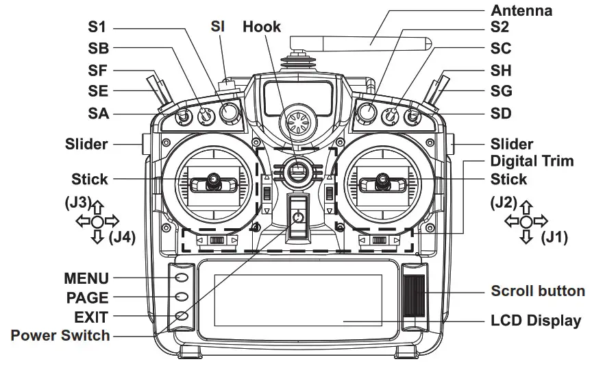
Switch Default Setting
- SA: 3 positions; Short Lever
- SB: 3 positions; Long Lever
- SC: 3 positions; Long Lever
- SD: 3 positions; Short Lever
- SF: 2 positions; Long Lever
- SH: 2 positions; Momentary, Long lever
Adjust sticks of Taranis Q X7/X7S ACCESS
Taranis Q X7/X7S ACCESS has 4 centred sticks and will not distinguish between the throttle stick and other sticks. You can change the stick mode and feeling according to your need.
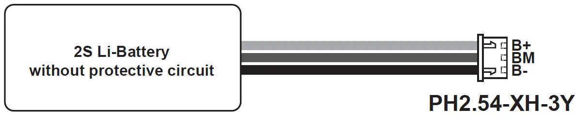
Battery Connector
Ensure that the battery connector polarity is correct when connecting batteries into the battery compartment, otherwise the Taranis Q X7/X7S ACCESS might be damaged.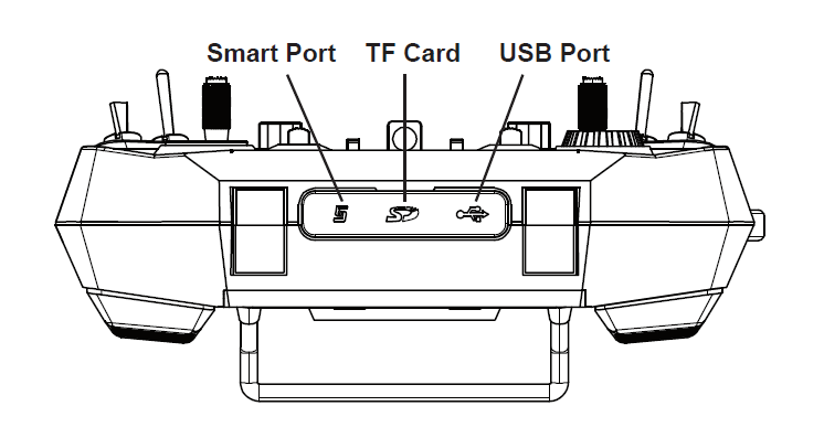
Specifications
- Model name: Taranis Q X7/X7S ACCESS
- Dimension: 202.2mm*189.4mm*96mm
- Weight: Taranis Q X7 ACCESS: 613g (without battery)
Taranis Q X7S ACCESS: 639g (without battery) - Operating system: Open source operating system
- Number of channels: 16 (ACCST D16) / 24 (ACCESS) channels
- Operating Voltage Range: 6.5V~8.4V (2 S LI-battery, not including LiFePO battery)
- Operating Current: [email protected] typ
- Operating Temperature: -10℃~60℃ (14℉~140℉)
- Backlight LCD resolution: 128*64
- Model memories: 60 models (expandable by Micro SD card)
- Smart Port, Micro SD card slot, Mini USB Port and DSC Port
Features
- Ergonomic and compact design
- Installed with ACCESS protocol
- Supports spectrum analyzer function
- High-speed module digital interface
- Supports wired training function
- Haptic vibration alerts and voice speech outputs
- Easily accessible battery compartment (*Batteries not included, adaptive with replaceable 18650 Li-ion batteries)
Comparison List
About USB 2S Li-battery balance charging :
The Green Power indicator LED state:
Led on: charging Led off: charge end Led flash: charge fault
Navigate the Menu
To navigate the menus, Taranis Q X7/X7S ACCESS has the following elements:
- Encoder Button
- MENU Button
- PAGE Button
- EXIT Button
Taranis Q X7/X7S ACCESS supports OpenTX system
Encoder Button
To navigate menus or widgets, turn the button to left or right as navigation.
MENU Button
To go to the [Model] menu, press the button.
To go to the [RADIO SETUP] menu, press the button, and hold for one second.
PAGE Button
To go to switch the page, press the button.
To go to the [Telemetry] menu, press the button, and hold for one second.
EXIT Button
To exit current page or operation widgets.
Menu Tree
Quick select options
Long press the Encoder Button there will generate a pop-up where the user can reset timer, reset telemetry values, reset all above, jump to the tele setup page.
Model Setup for Taranis Q X7/X7S ACCESS Internal RF Module
Step 1: Set the Mode for Taranis Q X7/X7S ACCESS Internal RF.
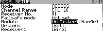
Go to the MODEL SETUP menu, and select the Internal RF, select [Mode] [ACCESS].
Step 2: Set the Channel Range
The Internal RF module of Taranis Q X7/X7S ACCESS supports up to 24 channels. The channel range is configurable, and needs to be confirmed before use.
Step 3: Set the Receiver Number
When you create a new model, the system will assign you a receiver number automatically, but this can be easily changed. The range of the receiver number is 00-63, with the default number being 01 (use 00 is not recommended). Once the receiver is set to desired number and is bound to the Taranis Q X7/X7S ACCESS, the bind procedure will not need to be repeated unless the receiver number is changed. In this case, either set the receiver number to the previous one or repeat the bind procedure.
Step 4: Registration
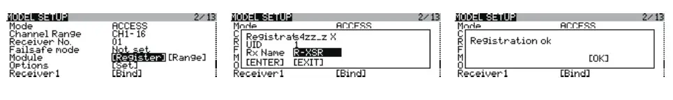
In ACCESS, select the Module [Reg] into Registration status. Then Press the F/S button and power on your receiver, and select the “RX Name XX” and [ENTER] to complete the Registration process then power down the receiver.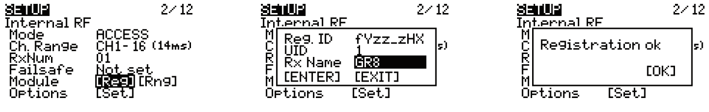
Step 5: Automatic binding (Smart Match )
Move the cursor to Receiver1[Bnd],and select it , power your receiver, select the RX, and complete the process, the system will confirm “Bind successful”. (You do not need to press the “F/S” button in ACCESS to Bind. Refer to the receivers manual for details)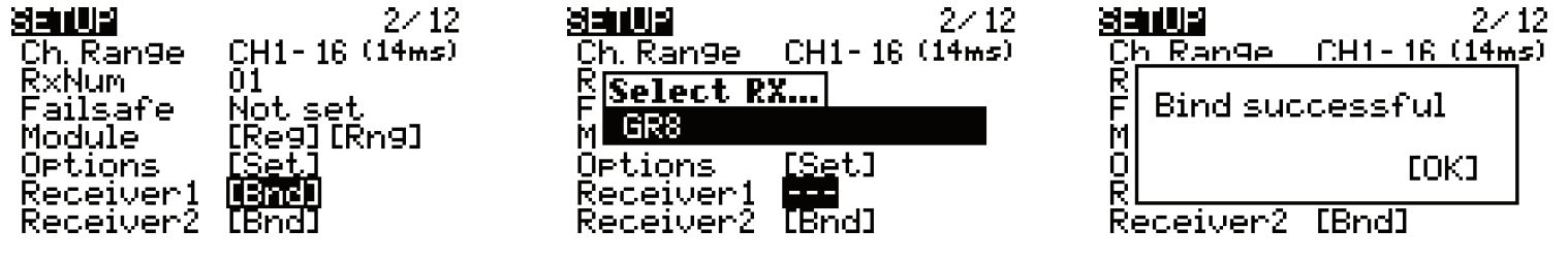
Step 6: Set Failsafe mode
There are 4 failsafe modes: No pulse, Hold, Custom and receiver.
No Pulse: on loss of signal the receiver produces no pulses on any channel. To use this type, select it in the menu and wait 9 seconds for the failsafe to take effect.
Hold: the receiver continues to output the last positions before signal was lost. To use this type, select it in the menu and wait 9 seconds for the failsafe to take effect.
Custom: pre-set to required positions on lost signal. Move the cursor to “Set” and press the Encoder Button, and you can see FAILSAFE SETTING screen below.
Move the cursor to the channel you want to set failsafe on, and press the Encoder Button.
When moving the corresponding sticks or switches, you will see the channel bar moving. Move the channel bar to the place you want for failsafe and long press the Encoder Button to finish the setting. Wait 9 seconds before failsafe takes effect.
Receiver: set the failsafe on the receiver (see receiver instructions) in ACCESS, select it in the menu and wait 9 seconds for the failsafe to take effect.
Step 7: Range
Range refers to Taranis Q X7/X7S ACCESS range check mode. A pre-flight range check should be done before each flying session. Move the cursor to [Rng] and press the Encoder Button. In range check mode, the effective distance will be decreased to 1/30. Press the Encoder Button or EXIT to exit.
FLYING SAFETY
Warning:
To ensure the safety of yourself and others, please observe the following precautions. Have regular maintenance performed. Although your Taranis Q X7/X7S ACCESS protects the model memories with non-volatile EEPROM memory (which does not require periodic replacement) and of a battery, it still should have regular check-ups for wear and tear. We recommend sending your system to your FrSky Service Center annually during your non-flying-season for a complete check-up and service.
Battery
Using a fully charged battery (DC 6.5~8.4V). A low battery will soon die, causing loss of control and a crash. When you begin your flying session, reset your transmitter’s built-in timer, and during the session pay attention to the duration of usage. Also, if your model used a separate receiver battery, make sure it is fully charged before each flying session. Stop flying long before your batteries become over discharged. Do not rely on your radio’s low battery warning systems, intended only as a precaution, to tell you when to recharge. Always check your transmitter and receiver batteries prior to each flight.
Where to Fly
We recommend that you fly at a recognized model airplane flying field. You can find model clubs and fields by asking your nearest hobby dealer. Always pay particular attention to the flying field’s rules, as well as the presence and location of spectators, the wind direction, and any obstacles on the field. Be very careful flying in areas near power lines, tall buildings, or communication facilities as there may be radio interference in their vicinity.
At the flying field
To prevent possible damage to your radio gear, turn the power switches on and off in the proper sequence:
- Pull throttle stick to idle position, or otherwise disarm your motor/engine.
- Turn on the transmitter power and allow your transmitter to reach its home screen.
- Confirm the proper model memory has been selected.
- Turn on your receiver power.
- Test all controls. If a servo operates abnormally, don’t attempt to fly until you determine the cause of the problem.
- Start your engine.
- Complete a full range check.
- After flying, bring the throttle stick to idle position, engage any kill switches or otherwise disarm your motor/engine.
Updates
FrSky is continuously adding features and improvements to our radio systems. Updating (via USB Port or the Micro SD card) is easy and free. To get the most from your new transmitter, please check the download section of the FrSky website for the latest update firmware and guide for adjusting your sticks. (www.frsky-rc.com)
FrSky Electronic Co., Ltd. www.frsky-rc.com
Contact us:
Add: F-4,Building C, Zhongxiu Technology Park, No.3 Yuanxi Road, Wuxi, 214125, Jiangsu, China
![]()
FrSky 2.4GHz ACCESS Taranis X9D Plus 2019/Taranis X9D Plus SE 2019 Manual
Introduction
The FrSky Taranis X9D Plus 2019 is a re-designed version with additions like an additional momentary button placed on the top left shoulder making it ergonomically friendly for DLG pilots to activate launch mode and features a program scroll wheel making it even easier to navigate the menus. The upgraded MCU is used in conjunction with a re-designed mainboard that further increases the computing capability and increases data storage. The upgrades not only improve the running of LUA scripts, it also optimizes overall performance like voice speech outputs.
The 2019 version uses the latest ACCESS communication protocol, it boasts 24 channels with a faster baud rate and lower latency with a high-speed module digital interface. Along with the new spectrum analysis function added to the OpenTX firmware, it is now possible to check the airwaves for RF noise with an accurate SWR indicator. This version will give you a further improved experience based on the classic Taranis remote control. Additionally, tons of extra upcoming features that ACCESS brings will make this an ideal transmitter for any skill level.
The SE 2019 version is installed with the upgraded switches and M9 hall sensor gimbals and features the addition of a PARA wireless trainer function which makes them compatible with the FrSky Free Link App and AirLink S.
Due to unforeseen changes in production, the information contained in this manual is subject to change without notice. Pay special attention to safety were indicated by the following marks:
Meanings of Special Markings
 DANGER – procedures that may lead to dangerous conditions and cause death/serious injury if not carried out properly.
 WARNING – Procedures which may lead to a dangerous condition or cause serious injury and even death to the user if not carried out properly or procedures where the probability of superficial injury or physical damage is high.
 CAUTION – Procedures where the possibility of serious injury to the user is small, but there is a danger of injury or physical damage, if not carried out properly.
 NOTE Steps, Tips or information
WARNING – Always keep electrical components away from children.
Layout
Switch
SA: 3 positions; Short lever
SB: 3 positions; Long lever
SC: 3 positions; Long lever
SD: 3 positions; Short lever
SE: 3 positions; Short lever
SF: 2 positions; Long lever
SG: 3 positions; Short lever
SH: 2 positions; Momentary, Long lever
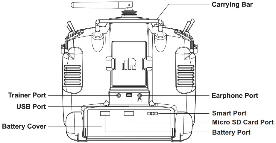
- Micro SD card is not provided with the shipment.
- USB port is for upgrading, reading/writing Micro SD cards, and internal memory of radio contents and charing (Includes USB cable in the package but without the adapter).
- Smart Port is for a firmware upgrade for all FrSky S.Port devices.
Specifications
- Model Name: Taranis X9D Plus 2019/Taranis X9D Plus SE 2019
- Dimension: 200*194*110 (L*W*H)
- Weight: Taranis X9D Plus 2019: 670g (without battery)
- Taranis X9D Plus SE 2019: 700g (without battery)
- Operating Current: [email protected] (Typ)
- Backlight LCD resolution: 212*64
- Model Memories: 60 models (Extendable by Micro SD card)
- Number of channels: 24 channels
- Operating Voltage Range: DC 6.5~8.4V
- Operating Temperature: -10~60 (14~140)
- Smart Port, Micro SD card slot, and USB Port OpenTX system
Features
- Classic Taranis form factor design
- High-speed module digital interface
- Easy launch momentary button
- Installed with ACCESS protocol
- Supports spectrum analyzer function
- Accurate SWR indicator
- Haptic vibration alerts and voice speech outputs
Comparison List
| Taranis X9D Plus 2019 | Taranis X9D Plus SE 2019 | |
| Operating System | OpenTX | OpenTX |
| Communication Protocol | ACCST D16 /ACCESS | ACCST D16 /ACCESS |
| Program Navigation Button | √ | √ |
| Easily Launch Momentary Button | √ | √ |
| 2S Li-Battery Charging System* | √ | √ |
| G9D Potentiometer Gimbal | √ | |
| M9 Hall Sensor Gimbal | √ | |
| Upgraded Switches | √ | |
| Wired Training System | √ | √ |
| PARA wireless training function ● PAPA High-speed training system with a lower latency ● Compatible with FrSky Free Link App and AirLink S via mobile devices |
√ |
About USB 2S Li-battery balance charing:
The Green Power indicator LED states:
Led on: charging
Led off: charge end
Led flash: charge fault
Note:
- Charge the battery with the adapter (power [email protected]) when you use the USB charging function.
- The lower the initial charging voltage, the better the charging effect is when the voltage difference between the two cells exceeds 50 mV.
Caution: Only 2S Li battery without a protective circuit can be applied to the balance charging system, and please do not charge any other types of battery.
Warnings for Battery
Do not remove the battery from the X9D Plus 2019/X9D Plus SE 2019 transmitter while the voltage warning is blinking as this could cause internal settings and memories to be destroyed. Do not use the transmitter if a “Backup Error” warning occurs.
Navigate the Menu
To navigate the menus, Taranis X9D Plus 2019/Taranis X9D Plus SE 2019 has the following elements:
- Scroll Button
- MENU Button
- PAGE Button
- EXIT Button
Taranis X9D Plus 2019/Taranis X9D Plus SE 2019 supports OpenTX system
Scroll Button
To navigate menus or widgets, roll the button to the left or right as navigation.
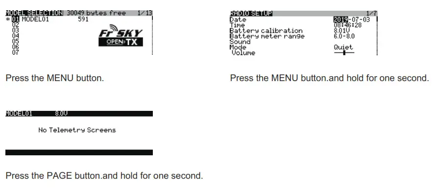
MENU Button
To go to the [Model] menu, press the button. To go to the [RADIO SETUP] menu, press the button, and hold for one second.
PAGE Button
To go to switch the page, press the button. To go to the [Telemetry] menu, press the button, and hold for one second.
EXIT Button
To exit current page or operation widgets.
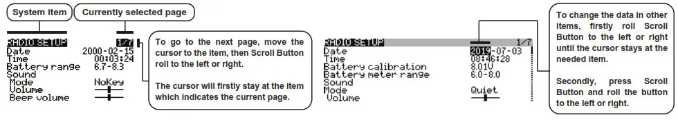
Where am I in the menu tree
System item Currently selected page
Overview of the menu tree
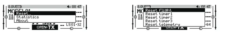
Quick select options
FrSky 2.4GHz ACCESS Taranis X9D Plus 2019/Taranis X9D Plus SE 2019 Manual
Long press the Scroll Button there will generate a pop-up where the user can reset the timer, reset telemetry values, reset all above, jump to the tele setup page.
Model Setup for Taranis X9D Plus 2019/Taranis X9D Plus SE 2019 Internal RF Module
Enter the MODEL SETUP menu.
Step 1: Set the Mode for Taranis X9D Plus 2019/Taranis X9D Plus SE 2019 Internal RF.
Go to the MODEL SETUP menu, and select the Internal RF, select [Mode] [ACCESS].
Step 2: Set the Channel Range
The Internal RF module of Taranis X9D Plus 2019/Taranis X9D Plus SE 2019 supports up to 24 channels. The channel range is configurable and needs to be confirmed before use.
Step 3: Set the Receiver Number
When you create a new model, the system will assign you a receiver number automatically, but this can be easily changed. The range of the receiver number is 00-63, with the default number being 01 (use 00 is not recommended). Once the receiver is set to the desired number and is bound to the Taranis X9D Plus 2019/Taranis X9D Plus SE 2019, the bind procedure will not need to be repeated unless the receiver number is changed. In this case, either set the receiver number to the previous one or repeat the bind procedure.
Step 4: Registration
In ACCESS, select the Module [Register] into Registration status. Then Press the F/S button and power on your receiver, and select the “RX Name XX” and [ENTER] to complete the Registration process then power down the receiver.
Note: If two or three receivers are used at the same time, the UID should be set to different values.
Step 5: Automatic binding (Smart MatchTM )
Move the cursor to Receiver1[Bind], and select it, power your receiver, select the RX and complete the process, the system will confirm “Bind successful”. (You do not need to press the “F/S” button in ACCESS to Bind. Refer to the receiver’s manual for details)
Step 6: Set Failsafe mode
There are 4 failsafe modes: No pulse, Hold, Custom, and receiver. No Pulse: on the loss of signal the receiver produces no pulses on any channel. To use this type, select it in the menu and wait 9 seconds for the failsafe to take effect.
Hold: the receiver continues to output the last positions before the signal was lost. To use this type, select it in the menu and wait 9 seconds for the failsafe to take effect.
Custom: pre-set to required positions on lost signal. Move the cursor to “Set” and press the Scroll Button, and you can see the FAILSAFE SETTING screen below. Move the cursor to the channel you want to set failsafe on, and press the Scroll Button. When moving the corresponding sticks or switches, you will see the channel bar moving. Move the channel bar to the place you want for failsafe and long-press the Scroll Button to finish the setting. Wait 9 seconds before the failsafe takes effect.
Receiver: set the failsafe on the receiver (see receiver instructions) in ACCESS, select it in the menu, and wait 9 seconds for the failsafe to take effect.
Step 7: Range
Range refers to Taranis X9D Plus 2019/Taranis X9D Plus SE 2019 range check mode. A pre-flight range check should be done before each flying session. Move the cursor to [Range] and press the Scroll Button. In range check mode, the effective distance will be decreased to 1/30. Press the Scroll Button or EXIT to exit.
FCC
This equipment has been tested and found to comply with the limits for a Class B digital device, pursuant to part 15 of the FCC Rules
CE
The product may be used freely in these countries: Germany, UK, Italy, Spain, Belgium, Netherlands, Portugal, Greece, Ireland, Denmark, Luxembourg, Austria, Finland, Sweden, Norway, France and Iceland.
FLYING SAFETY
Warning:
To ensure the safety of yourself and others, please observe the following precautions.
Have regular maintenance been performed? Although your Taranis X9D Plus 2019/Taranis X9D Plus SE 2019 protects the model memories with non-volatile EEPROM memory (which does not require periodic replacement) and of a battery, it still should have regular check-ups for wear and tear. We recommend sending your system to your FrSky Service Center annually during your non-flying-season for a complete check-up and service.
Battery
Using a fully charged battery (DC 6.5~8.4V). A low battery will soon die, causing loss of control and a crash. When you begin your flying session, reset your transmitter’s built-in timer, and during the session pay attention to the duration of usage. Also, if your model using a separate receiver battery, make sure it is fully charged before each flying session.
Stop flying long before your batteries become over-discharged. Do not rely on your radio’s low battery warning systems, intended only as a precaution, to tell you when to recharge. Always check your transmitter and receiver batteries prior to each flight.
Where to Fly
We recommend that you fly at a recognized model airplane flying field. You can find model clubs and fields by asking your nearest hobby dealer.
Always pay particular attention to the flying field’s rules, as well as the presence and location of spectators, the wind direction, and any obstacles on the field. Be very careful flying in areas near power lines, tall buildings, or communication facilities as there may be radio interference in their vicinity.
At the flying field
To prevent possible damage to your radio gear, turn the power switches on and off in the proper sequence:
- Pull throttle stick to idle position, or otherwise disarm your motor/engine.
- Turn on the transmitter power and allow your transmitter to reach its home screen.
- Confirm the proper model memory has been selected.
- Turn on your receiver power.
- Test all controls. If a servo operates abnormally, don’t attempt to fly until you determine the cause of the problem.
- Start your engine.
- Complete a full range check.
- After flying, bring the throttle stick to idle position, engage any kill switches or otherwise disarm your motor/ engine.
If you do not turn on your system on and off in this order, you may damage your servos or control surfaces, flood your engine, or in the case of electric-powered or gasoline-powered models, the engine may unexpectedly turn on and cause a severe injury.
Make sure your transmitter can’t tip it over. If it is knocked over, the throttle stick may be accidentally moved, causing the engine to speed up. Also, damage to your transmitter may occur.
In order to maintain complete control of your aircraft, it is important that it remains visible at all times. Flying behind large objects such as buildings, grain bins, etc. must be avoided. Doing so may interrupt the radio frequency link to the model, resulting in loss of control.
Do not grasp the transmitter’s antenna during flight. Doing so may degrade the quality of the radio frequency transmission and could result in loss of control.
As with all radio frequency transmissions, the strongest area of signal transmission is from the sides of the transmitter’s antenna. As such, the antenna should not be pointed directly at the model. If your flying style creates this situation, easily move the antenna to correct this situation.
Before taxiing, be sure to extend the transmitter antenna to its full length. A collapsed antenna will reduce your flying range and cause a loss of control. It is a good idea to avoid pointing the transmitter antenna directly at the model since the signal is weakest in that direction.
Don’t fly in the rain! Water or moisture may enter the transmitter through the antenna or stick openings and cause erratic operation or loss of control. If you must fly in wet weather during a contest, be sure to cover your transmitter with a plastic bag or waterproof barrier. Never fly if lightning is expected.
Updates
FrSky is continuously adding features and improvements to our radio systems. Updating (via USB Port or the Micro SD card) is easy and free. To get the most from your new transmitter, please check the download section of the FrSky website for the latest update firmware and guide for adjusting your sticks. (www.frsky-rc.com)
FrSky is continuously adding features and improvements to our products. To get the most from your product, please check the download section of the FrSky website www.frsky-rc.com for the latest update firmware and manuals
FrSky Electronic Co., Ltd.
www.frsky-rc.com
Contact us: [email protected]
Add: F-4, Building C, Zhongxiu Technology Park, No.3 Yuanxi Road, Wuxi, 214125, Jiangsu, China
Technical Support: [email protected]
FrSky 2.4GHz ACCST G-RX8 User Manual
Introduction
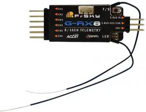
Thank you for purchasing FrSky G-RXB 8116th telemetry receiver. In order to fully enjoy the benefits of this system, please read the instruction manual carefully and set up the device as described below.
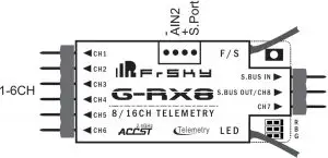
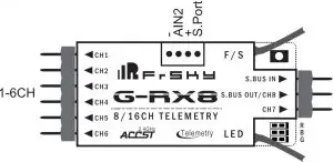
Overview
Specifications
- Dimension: 56.26mmx17mmx8mm (L • W • H)
- Weight: 5.89
- Number of Channels: 16CH (1-8ch/9-16ch from conventional channel outputs, 1-16th from SBUS port or combine two receivers to become a 16 channels receiver with G-RX8,RX8R,X8R).
- Operating Voltage Range: 4.0-WV
- Operating Current: 100mA@5V
- Operating Range: full range
- Firmware Upgradable
- Compatibility: D16 mode
Features
- Variometer sensor: the measures is -700m-10000m with o.1m(lugh precision version) .support altimeter(the rate formula Is 1-16.7m/s).
- GRXB supports the redundancy function for the master and slave receivers. The master receiver receives SBUS signal from the slave receiver. The master receiver must be GRX8, and the slave receiver can be any brand receiver with SBUS output (for example, FrSky X8R. X6R. X4RSB. XSR, XM. XM+, G-RX8. L9R, etc)
Note: make sure telemetry Is disabled on the slave receiver when the slave receiver Is FrSky X series receiver. XM+ is recommended as the slave receiver.
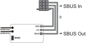
Both the master and the slave receiver signal from radio / transmitter module. The PWM outputs from the stronger signal port. Smart Port (S. Port) is a signal wire full duplex digital transmission interface developed by FrSky Electronic Co., Ltd. All products enabled with Smart Port (including XJT module, RX8R receiver, new hub-less sensors, new Smart Dashboard, etc), serial port user data and other user input/output devices can be connected without limitations for numbers or sequences at a high transmis-sion speed.
Binding Procedure
Binding is the process of uniquely associating a particular receiver to a transmitter/transmitter module. A transmitter/transmitter module can be bound to multiple receivers (not to be used simultaneously).A receiver can only be bound to one transmitter/transmitter module. Follow the steps below to finish the binding procedure.
- Put the transmitter/transmitter module into binding mode
- For Taranis X9D/X9D Plus/X9E and Taranis Q X7, turn on the transmitter, go to the MENU — MODEL SETUP — PAGE 2, choose Internal or External RF, and select BIND.
- For Horus X12S, turn on the transmitter, go to the RF SYSTEM, choose Internal or External RF, and select BIND under STATE.
- For transmitter module (XJT as an example), turn on the transmitter while holding the FS button on the module, release the button and the RED LED on XJT module flash.
- Connect the battery to the receiver while holding the F/S button on the receiver. The RED LED on the receiver will flash, indicating the binding process is completed.
- Turn off both the transmitter and the receiver.
- Turn on the transmitter and connect the battery. The GREEN LED on the receiver indicates the receiver is receiving commands from the transmitter. The receiver/transmitter module binding will not have to be repeated, unless one of the two is replaced.
Note: After binding procedure is completed, recycle the power and check if the receiver is really under control by linked transmitter.
When combine two receivers to become a 16CH receiver, you need to disable telemetry on either one of the two receiver’s. How to switch SBUS / PWM mode
- Turn on the receiver, if the BLUE LED on the receiver lights , the receiver stays in SBUS mode Otherwise, it stays in the PWM mode.
- Connect CH1 and CH2 by the jumper before Binding, the receiver will stay in PWM mode. The receiver will enter into SBUS mode without jumper connecting.
Note:
- SBUS Mode : CH1—CH6 output high precision PWM signal (Error < 0.5 us) , SBUS IN is used for redundancy function &CH8 outputs SBUS signal &CH7 no outputs.
- PWM Mode : CH1—CH4 output high precision PWM signal (Error < 0.5 us) , CH5—CH8 output ordinary precision, SBUS IN / SBUS OUT will be disabled.
How to Disable/Enable altimeter function
- The factory default setting is “enabled”.
- in case you want to disable altimeter functionality bring the receiver into normal operational mode , hold the F/S button to bind > 3 s, the BLUE LED will flash 3 times, then switch successfully and the function will be disabled. (If you want to enable the function, just repeat steps will be okay).
How to switch the output 1 — 8/9 — 16CH
- The receiver default output 1 — 6 CH (or 8CH),If the user uses the X12S, you need to choose corresponding operations when the remote control to bind. If user uses X7 / X9, you need to connect CH3 and CH4 by the jumper , and then perform binding process , after the successful binding , output channel change successfully. If outputs 9 — 16CH, and user needs to change back to 1 — 8CH, follow the same operation.
Failsafe
Failsafe is a useful feature in which all controls move to a preset position whenever the control signal is lost for a period of time. G-RX8 supports failsafe function for all channels. Follow the steps below to set failsafe positions for each channel:
- Bind the receiver first and turn on both the transmitter and the receiver;
- Move the controls to the desired failsafe position for all channels; 3. Press briefly the F/S button on the receiver (less than 1 second). The Green LED will flash twice, indicating the failsafe position has been set in the receiver.
To disable the failsafe function, re-bind the receiver. Failsafe is recommended to set when system is firstly used, or receiver has been re-bound. Follow steps below to set failsafe.
Option-1:
How to set failsafe to a user-determined state on lost signal:
- Bind the receiver to the transmitter module first and turn on both the transmitter and the receiver;
- Move the controls to desired failsafe position for all channels;
- Press briefly the F/S button on the receiver and you are done.
Option-2:
How to set failsafe for no pulses on lost signal:
- Turn off the transmitter, power on the receiver, and then press briefly the F/S button on the receiver.
Note:
You even have the choice to setup failsafe configuration by using your transmitter.Please refer your TX operating manual how to setup failsafe positions or hold / no pulse options. If failsafe is not set, failsafe default will hold last position before signal is lost. In this case, there exists risk that your model will fly away or cause injury.
For more details, please check the complete manual for G-RX8 from www.frsky-rc.com – Download -Manual. Should you have other questions, please send e-mails to FrSky technical support [email protected].
FrSky is continuously adding features and improvements to our products. To get the most from your product, please check the download section of the FrSky website www.frsky-rc.com for the latest update firmware and manuals
FrSky Electronic Co., Ltd
www.frsky-rc.corn
Contact us :[email protected]
Add:F-4,Building C, Zhongxiu Technology Park, No.3 Yuanxi Road, Wuxi, 214125, Jiangsu, China
Technical Support: [email protected]
FrSky Access Horus X10/ X10s Express Instruction
Introduction
With the demand for further extending the legacy of the Horus Series Transmitters, the Horus X10/S Express version was born. With many new updates like applying the ACCESS protocol and hardware tweaks.
Horus X10/S Express use the ACCESS communication protocol, it boasts 24 channels with a faster baud rate and lower latency equipped with a high-speed module digital interface. Along with the new spectrum analysis function and added FrOS/OpenTX firmware, it is now possible to check the airwaves for RF noise.
Both X10 and X10S Express support balancing charge for 2S Li-ion battery via a collateral USB cable. The accessible battery compartment design is another change worth mentioning, with two 18650 Li-ion batteries you can expect to be able to fly all day. The Express carries forward all of their predecessor’ features like the industrial LCD color screen, and the highly-accuracy M10/MC12P hall sensor gimbals which offer the most precise control. Additionally, it features a remarkable PARA wireless trainer function which also makes them compatible with the FrSky Free Link App and AirLink S. All that makes the Express version an ideal transmitter for, gliders, helis, multirotor and every type of fixed-wing imaginable. 
Overview
Switch default Settings
- SA: 3 positions; Short Lever
- SB: 3 positions; Long Lever
- SC: 3 positions; Long Lever
- SD: 3 positions; Short Lever
- SE: 3 positions; Short Lever
- SF: 2 positions; Long Lever
- SG: 3 positions; Short Lever
- SH: 2 positions; Momentary, Long lever
Output Map screen
- Micro SD card is not provided with shipment.
- USB port is for upgrading, reading/writing Micro SD cards and internal memory of radio contents and charging (Includes USB cable in packge but without the adapter).
- Smart Port is for firmware upgrade for all FrSky S.Port devices.
Cautions on handling External antenna
- Do not touch the antenna during operation. Doing so could interfere with transmission, causing a crash.
- Do not carry the transmitter by the antenna. The antenna wire could break and prevent transmission.
- Do not pull the antenna forcefully. The antenna wire could break and prevent transmission.
Specifications
- Dimension: 213*225*112 mm (L*W*H)
- Weight: Horus X10 Express: 900g (without battery)
Horus X10S Express: 950g (without battery) - Operating system: FrOS / OpenTX
- Internal RF module: ISRM-S-X10
- Number of Channels: 24 channels
- Operating Voltage Range: 6.5 ~ 8.4V (2S Li-battery)
- Operating Temperature: -10℃~60℃ (14℉~140℉)
- Operating Current: [email protected] (typ)
- Charging Current: ≤1A ±200mA
- USB Adaptor Voltage: 5V+0.2V
- USB Adaptor Current: >2.0A
- Backlit LCD resolution: 480*272
- Compatibility: ACCST D16 and ACCESS receivers
Features
- High-speed module digital interface with installed ACCESS protocol
- Supports spectrum analyzer function
- Supports wired training function
- New PARA wireless training system
- High-speed training system with a lower latency
- Compatible with FrSky Free Link App and AirLink S via mobile devices
- Dual internal antennas and a single detachable external antenna work in unison to create a robust link
- Antenna detection and SWR warning
- Industrial LCD: 480*272 readable outdoor color screen
- Supports 2S Li-battery balancing charge with mini USB interface
- Easily accessible battery compartment (*Batteries not included)
- M10 hall sensor gimbals and extendable stick ends (Horus X10 Express)
- MC12P all CNC digital higher accuracy ten bearings hall sensor gimbals and extendable stick ends (Horus X10S Express)
Notes and Warnings for Battery & Charger
About USB 2S Li-battery balance charging :
The Green Power indicator LED state:
Led on: charging
Led off: charge end
Led flash: charge fault
Note:
- Charge the battery with the USB adapter (Voltage:5V+0.2V Current:>2.0A) when you use the USB charging function.
The lower the initial charging voltage, the better the charging effect is when the voltage difference between the two cells exceed 50 mV.
Caution:
Only 2S Li-battery without protective circuit can be applied to balance charging system, and please do not charge any other types of battery.
Model Setup for Horus X10 Express/Horus X10S Express Internal RF Module
The internal RF module of FrSky Horus X10 Express/Horus X10S Express is newly developed by FrSky under the name of ISRM-S-X10.
Enter the RF SYSTEM menu (for details, download it from FrSky website)
Step 1:
Set the Mode for Horus X10 Express/Horus X10S Express internal RF corresponding to your receiver (ACCESS,ACCST D16)
— Press the MODEL button, Choose the INT MODULE.Then turn ON INTERNAL RF ,select the OUTSIDE or INSIDE ANTENNA( Dual internal antennas and external antenna work simultaneously while selecting the OUTSIDE ANTENNA.)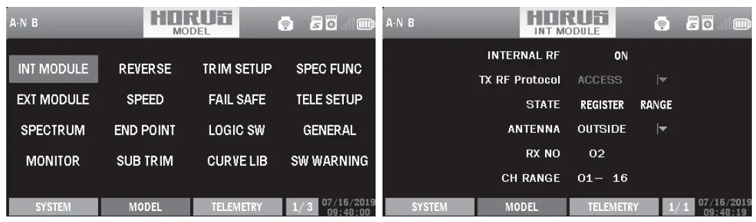
Step 2:Set the Channel Range
The internal RF module of Horus X10 Express/X10S Express support 24 channnels. the channel range is configurable, and it needs to be double checked before use.
Step 3: Set the Receiver Number
When you create a new model, the system will assign you a receiver number automatically, but this can be easily changed. The range of the receiver number is 01-64, with the default number being 01. Once the receiver is set to the desired number and is bound to the Horus X10 Express/Horus X10S Express, the bind procedure will not need to be repeated unless the receiver number is changed, In this case, set the receiver number to the previous one, repeat the bind procedure.
Step 4 : Registration
In ACCESS, select the STATE [Register] into Registration status. Then Press the F/S button and power on your receiver, and select the “RX Name XX” and [REGISTER] to complete the Registration process then power down the receiver.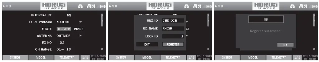
Step 5: Automatic binding (Smart Match)
Move the cursor to Rx1[BIND],and select it, power your receiver, select the RX, and complete the process, the system will confirm “Bind successed”. (You do not need to press the “F/S” button in ACCESS to Bind. Refer to the receivers manual for details)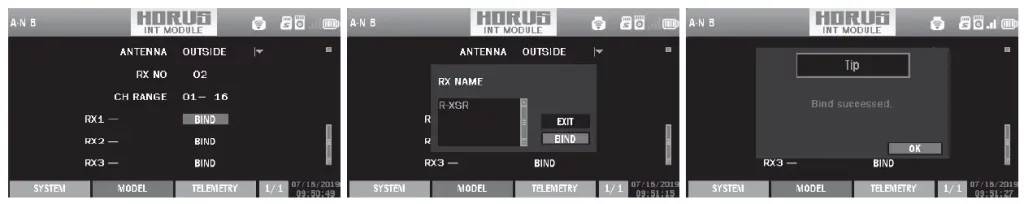
Step 6: Set Failsafe mode
There are 3 failsafe modes when enable: No Pulse, Hold, Custom.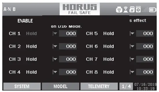
- No Pulse: on loss of signal the receiver produces no pulses on any channel. To use this type, select it in the menu and wait 9 seconds for the failsafe to take effect.
- Hold: the receiver continues to output the last positions before signal was lost. To use this type, select it in the menu and wait 9 seconds for the failsafe to take effect.
- Custom: pre-set to required positions on lost signal. Move the cursor to the failsafe mode of channel and press Encoder, then choose the Custom mode. Move the cursor to the channel you want to set failsafe on, and press Encoder.
Then rotate the Encoder to set your failsafe for each channel and short press Encoder to finish the setting. Wait 9 seconds before the failsafe takes effect.
Notice: - When failsafe is disabled on Horus X10 Express/Horus X10S Express side, the failsafe set on receiver side will be used.
- SBUS port always outputs, does not support the No Pulse failsafe mode. Set “Hold” or “Custom” for SBUS port.
Step 7: Range
Range refers to Horus X10/Horus X10S EXPRESS range check mode. A pre-flight range check should be done before each flying session. Move the cursor to “STATE”, scroll the Encoder to select “RANGE” mode and press Encoder. In range check mode, the effective distance will be decreased to 1/30. Press the Encoder again, turn to normal state.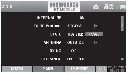
Model Setup for Horus X10 Express/Horus X10S Express External RF Module
FCC Statement
Changes or modifications not expressly approved by the party responsible for compliance could void the user’s authority to operate the equipment.
NOTE: This equipment has been tested and found to comply with the limits for a Class B digital device, pursuant to Part 15 of the FCC Rules. These limits are designed to provide reasonable protection
against harmful interference in a residential installation.
This equipment generates uses and can radiate radio frequency energy and, if not installed and used in accordance with the instructions, may cause harmful interference to radio communications. Make sure you set the country code to your corresponding country to match the regulations. However, there is no guarantee that interference will not occur in a particular installation. If this equipment does cause harmful interference to radio or television reception, which can be determined by turning the equipment off and on, the user is encouraged to try to correct the interference by one or more of the following measures:
- Reorient or relocate the receiving antenna.
- Increase the separation between the equipment and receiver.
- Connect the equipment into an outlet on a circuit different from that to which the receiver is connected.
- Consult the dealer or an experienced radio/TV technician for help.
RF warning statement:
The device has been evaluated to meet general RF exposure requirement. The device can be used in portable exposure condition without restriction.
FLYING SAFETY
Warning
To ensure the safety of yourself and others, please observe the following precautions.
Have regular maintenance performed. Although your Horus X10 Express/Horus X10S Express protects the model memories with non-volatile EEPROM memory (which does not require periodic replacement) and of a battery, it still should have regular check-ups for wear and tear. We recommend sending your system to your FrSky Service Center annually during your non-flying-season for a complete check-up and service.
Battery
Charge the batteries! Using the standard Horus battery and charger, always recharge the transmitter and receiver batteries before each flying session. A low battery will soon die, causing loss of control and a crash. When you begin your flying session, reset your transmitter’s built-in timer, and during the session pay attention to the duration of usage. Also, if your model uses a separate receiver battery, make sure it is fully charged before each flying session.
Where to Fly
We recommend that you fly at a recognized model airplane flying field. You can find model clubs and fields by asking your nearest hobby dealer.
Always pay particular attention to the flying field’s rules, as well as the presence and location of spectators, the wind direction, and any obstacles on the field. Be very careful flying in areas near power lines, tall buildings, or communication facilities as there may be radio interference in their vicinity.
At the flying field
To prevent possible damage to your radio gear, turn the power switches on and off in the proper sequence:
- Pull throttle stick to idle position, or otherwise disarm your motor/engine.
- Turn on the transmitter power and allow your transmitter to reach its home screen.
- Confirm the proper model memory has been selected.
- Turn on your receiver power.
- Test all controls. If a servo operates abnormally, don’t attempt to fly until you determine the cause of the problem. (For PCM systems only: Test to ensure that the Failsafe settings are correct by waiting at least 2 minutes after adjusting then, turning the transmitter off and confirming the proper surface/ throttle movements. Turn the transmitter back on.)
- Start your motor/engine.
- Complete a full range check.
- After flying, bring the throttle stick to idle position, engage any kill switches or otherwise disarm your motor/engine.
If you do not turn on your system on and off in this order, you may damage your servos or control surfaces, flood your engine, or in the case of electric-powered or gasoline-powered models, the engine may unexpectedly turn on and cause a severe injury.
Make sure your transmitter can’t tip it over. If it is knocked over, the throttle stick may be accidentally moved, causing the engine to speed up. Also, damage to your transmitter may occur.
In order to maintain complete control of your aircraft it is important that it remains visible at all times. Flying behind large objects such as buildings, grain bins, etc. must be avoided. Doing so may interrupt the radio frequency link to the model, resulting in loss of control.
Do not grasp the transmitter’s antenna during flight. Doing so may degrade the quality of the radio frequency transmission and could result in loss of control.
As with all radio frequency transmissions, the strongest area of signal transmission is from the sides of the transmitter’s antenna. As such, the antenna should not be pointed directly at the model. If your flying style creates this situation, easily move the antenna to correct this situation
Before taxiing, be sure to extend the transmitter antenna to its full length. A collapsed antenna will reduce your flying range and cause a loss of control. It is a good idea to avoid pointing the transmitter antenna directly at the model, since the signal is weakest in that direction.
Don’t fly in the rain! Water or moisture may enter the transmitter through the antenna or stick openings and cause erratic operation or loss of control. If you must fly in wet weather during a contest, be sure to cover your transmitter with a plastic bag or waterproof barrier. Never fly if lightning is expected.
Li-Ion Battery Safety and Handling instructions
It’s important to understand the operating characteristics of Li-Ion battery. Read the specifications printed on the label of your Li-Ion battery and charger prior to use. Failure to follow the these precauti ons can quickly result in severe, permanent damage to the battery and its surroundings and possibly result in a FIRE!
IMPORTANT PRECAUTIONS
- Do not leave a Li-Ion battery unattended at any time while being charged or discharged.
- Do not attempt to charge Li-Ion batteries with a charger that is NOT designed for Li-Ion batteries, as permanent damage to the battery and charger could result.
- Always charge Li-Ion batteries in a fireproof location. Do not charge or discharge Li-Ion batteries on carpet, a cluttered workbench, near paper, plastic, vinyl, leather or wood, or inside an R/C model or full-sized automobile!
- Monitor the charge area with a smoke or fire alarm.
- Do not charge Li-Ion battery at currents greater than the “1C” rating of the battery (“C” equals the rated capacity of the battery).
- Do not allow Li-Ion cells to overheat at any time! Cells which reach greater than 140 degrees Fahrenheit (60°C) should be placed in a fireproof location.
- Li-Ion cells will not charge fully when too cold or show full charge.
- It is normal for the batteries to become warm during charging, but if the charger or battery becomes excessively hot disconnect the battery from the charger immediately!! Always inspect for potential damage any battery which has previously overheated for potential damage, and do not re-use if you suspect it has been damaged in any way.
- Do not use a Li-Ion battery if you suspect physical damage has occurred to the pack. Carefully inspect the battery for even the smallest of dents, cracks, splits, punctures or damage to the wiring and connectors.
- DO not allow the battery’s internal electrolyte to get into eyes or on skin—wash affected areas immediately if they come in.
Updates
FrSky is continuously adding features and improvements to our radio systems. Updating (via the Micro SD card in Horus X10 Express/Horus X10S Express Micro SD Card Slot) is easy and free. To get the most from your new transmitter, please check the download section of the FrSky website www.frsky-rc.com, for the latest update firmware and how-to guide.
Horus X10 Express/Horus X10S Express installed the FrSky FrOS operation system. Do not hesitate to contact FrSky if you have ideas and suggestions for current and future radio systems, or if you are willing to join the FrSky developing union to be part of future projects.
The currently pre-installed firmware of Horus X10 Express/Horus X10S Express is FrSky FrOS firmware, developed and well tested by FrSky. The transmitter also supports the open source OpenTX firmware.
More information about OpenTX can be found on: http://openrcforums.com.
FrSky Electronic Co., Ltd. www.frsky-rc.com
Contact us: [email protected]
Add: F-4,Building C, Zhongxiu Technology Park, No.3 Yuanxi Road, Wuxi, 214125, Jiangsu, China
Technical Support: [email protected]
Instruction Manual for DHT
Introduction
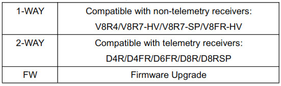
Description & compatibility
Specifications
Dimension: 55*34*8mm (2.17”L x 1.34”W x 0.32”T)
Operating Voltage Range: 6.0V-13.0V
Operating Current: 50mA
Output Power: 60mW
Resolution: 3072 (>11bit)
SetUp
Installation process
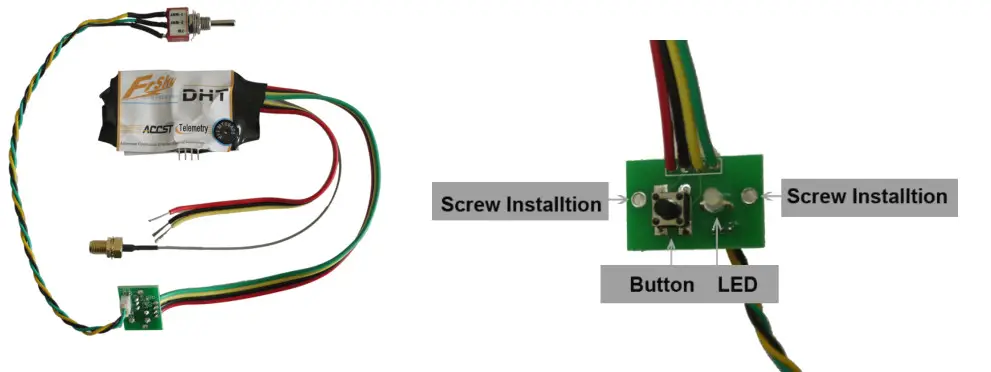
- Open the transmitter and find a clear position to locate the DHT module, the antenna connector, the small electronic panel. The location of the antenna should be such that there is no metal touching the antenna after it is mounted.
- Locate the battery power supply line, GND and PPM signal line. These are often a three-wire bundle or ribbon cable connected to a separate transmitter circuit card. Use a voltmeter and/or oscilloscope to help identify the function of each wire. (RED→V+; BLACK→GND; YELLOW→PPM)
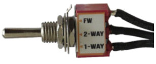
- Drill four holes on the transmitter as the picture guided, two holes on both sides are designed for screw installation, others for green/red color LED and the button. (see picture above ); then drill another hole for installing toggle switch in a suitable place.
- Attach the transmitter antenna to the RF connector. Turn the transmitter power on and check the power indicator LED on the new DHT control panel. It is normally light RED.
Bind procedure
- Ascertain that the transmitter is in the PPM mode. Turn the transmitter off.
- Change toggle switch position to required mode to work with the receiver you are using. See the table above.
- Turn your transmitter on while holding the F/S button on the transmitter module. Release it in a few seconds. The RED LED on the transmitter module will flash, indicating the transmitter is ready to bind to the receiver.
- Connect the battery to the receiver while holding the F/S button on the receiver. The RED LED on the receiver will flash, indicating the binding process is completed. Turn off both the transmitter and receiver.
- Turn on the transmitter and re-connect the battery to the receiver. The RED SOLID LED on the receiver will indicate the receiver is receiving commands from the transmitter. The receiver/transmitter binding will not have to be repeated unless one of the two is replaced.
After the above steps are completed, both the transmitter and the receiver are ready to be used.
Warning: When working with two-way telemetry receivers (D8R or D6FR), make sure that the battery and servos are plugged into CH1~CH8/CH1~CH6 rather than the side port (A2/Rx), otherwise damage may occur.
Range Check
A pre-flight range check should be done before each flying session. Reflections from nearby metal fences, concrete buildings, or trees can cause loss of signal both during the range check and during flight.
The following steps are to be followed to perform the range check of the model before flight:
Place the model at least 60cm (two feet) above non-metal contaminated ground (e.g. on a wooden bench).
- The receiver antennas should be separated in the model, as described in the receiver manual, and not touching the ground.
- Place the antenna of the transmitter in a vertical position.
- Turn on the transmitter and receiver, press the F/S button of the transmitter for 4 seconds to enter range check mode, the RED LED of the transmitter module will be off, GREEN LED will flash rapidly, the BEEPER will sound. The effective distance will be decreased to 1/30 of full range.
- Walk away from the model while simultaneously operating the controls on the transmitter, confirming that all controls operate normally to a distance of at least 30 meters (~30 yds).
- Press the F/S button for 1S-4S to exit range check mode, the RED LED will be back on, indicating normal operation is activated.
Signal lose Indicator and failsafe setting
In some special circumstances, such as strong interference, the signal may be lost. When a signal is lost in a short period, the receiver continues to try to search for the transmitter, at the same time it keeps the last command from the transmitter, until a new command is received.
Failsafe is a useful feature in which all controls move to a preset position whenever the control signal is lost for a period of time. FrSky receivers support failsafe function for all channels. Follow the steps below to set failsafe:
- Bind the receiver first and turn on both transmitter and receiver;
- Move all controls to that desired as the failsafe position;
- Press briefly the F/S button of the receiver (less than 1 second), the transmitter module will make a long “beep” (for D8R only) or the GREEN LED of the receiver will flash twice, indicating the failsafe position has been set in the receiver.
To disable the failsafe function, re-bind the receiver.
Other relevant documents can be found on the FrSky web page at these addresses:
- For V8 series: http://www.frsky-rc.com/download.asp?id=21
- For Two Way series: http://www.frsky-rc.com/download.asp?id=22
Instruction Manual for FrSky R9 SX OTA Receiver
Introduction
The R9 SX is the enhanced version of the R9 Slim series of long-range capable receivers. It adds 3-pin servo connectors with 6 full PWM channels and utilizes the dual-antenna design. The light-weight protective shell has a Multi-use 6-pin plug to bring you additional functions like signal redundancy, telemetry feedback, external battery detection and more.
Flexibility is a key feature of this receiver. The 6 PWM channels can be converted to 4 PWM channels with the additional Ch5 and Ch6 can be configured as an alternative S.Port and SBUS outputs to the 6-pin port. The enhanced design proves to be more durable, and in conjunction with the latest ACCESS firmware, the two are now synchronized and we are able to unlock the true potential of the ACCESS protocol.
Overview
Specifications
- Frequency: 868MHz / 915MHz
- Dimension: 36*17*7mm (L*W*H) / 47.5*20.5*11mm (L*W*H) (including case and pins)
- Weight: 8.8g / 13g (including case and pins)
- Numbers of Channel: 6 PWM / 16 SBUS (CH16 outputs RSSI)
- Operating Voltage: DC 3.5V~12.6V
- Operating Current: < 100mA@5V
- Compatibility: R9M Lite / R9M Lite Pro / R9M 2019 with ACCESS firmware
Features
- ACCESS protocol and supports OTA functions
- 915MHz / 868MHz long-range with low latency
- Enhanced and durable design
- 6 standard servo connectors (default PWM channel)
- Switchable CH5 / CH6 into S.Port / SBUS Output channels
- Support S.Port / F.Port (Configurable in OpenTX / FrOS menu)
- Signal redundancy function
- External battery detection
- Detachable Ipex1 connector antenna

Smart Port (S. Port) is a signal wire full duplex digital transmission interface developed by FrSky Electronic Co., Ltd. All products enabled with Smart Port (including XJT module, XSR, X6R and X8R receiver, new hub-less sensors, new Smart Dashboard, etc), serial port user data and other user input/output devices can be connected without limitations for numbers or sequences at a high transmission speed.
Registration & Automatic binding (Smart Match )
With the FrSky ACCESS protocol, the transmitter/transmitter module can bind receiver without using the “F/S” button. Follow the step below to finish the Registration & binding procedure:
- Put the transmitter/transmitter module into [Reg] status.
- For Taranis X-Lite Pro and R9M Lite Pro as an example, turn on the transmitter, go to the MENU-MODEL SETUP-PAGE 2, choose External RF-Mode R9MLP ACCESS, then select [Reg].
- Connect the battery to the receiver while holding the F/S button on the receiver. The RED LED and GREEN LED on the receiver will be on, indicating into the [Reg] status. Select [ENTER] on the transmitter, The RED LED and GREEN LED on the receiver will flash, and the transmitter displays [Registration ok].
- Turn off the receiver.
- Move the cursor to select the receiver 1 [Bind].
- Connect the battery to the receiver, the GREEN LED on the receiver will be on, indicating into the [Bind] status. Select the RX, and the transmitter displays [Bind successful].
- The transmitter exit [Bind], GREEN LED will flash, RED LED will be off, indicating working normally
About OTA function
For Taranis X-Lite Pro as an example, go to the SD CARD 2/7, and select the FW, press the enter button, select [Flash receiver by ext. OTA], power on the receiver, select the RX, go to the [ENTER], complete the flash process, the transmitter will display [Flash successful]. Re-power the receiver and wait for 3 seconds, the Green LED starts flashing indicates the receiver works properly at the moment.
Note: Update the firmware after the receiver gets binded.
How to enable/disable the receiver telemetry
For Taranis X-Lite Pro as an example, go to the External RF, select the Receiver, press the ENTER button, select the options, and enable/disable the telemetry.
How to switch CH5/CH6 into S.Port/SBUS Output channels
For Taranis X-Lite Pro as an example, select the Receiver, press the ENTER button, select the Options, and select the CH5/CH6 Turn to the S.Port/SBUS Output channels.
How to switch the F.Port
For Taranis X-Lite Pro as an example, select the Receiver, press the ENTER button, select the Options,and select F.Port.
How to Set Failsafe mode (on the transmitter)
There are 3 failsafe modes: No Pulse, Hold, Custom
- No Pulse: on loss of signal the receiver produces no pulses on any channel. To use this type, select it in the menu and wait 9 seconds for the failsafe to take effect.
- Hold: the model will maintain the last position after the signal is lost. To use this type, select it in the menu and wait 9 seconds for the failsafe to take effect.
- Custom: the customized position of each individual channel. The model will move to the pre-set position after the signal is lost.
Move the cursor to “Set” and press ENTER, you will see FAILSAFE SETTING screen below. Move the cursor to the channel you want to set failsafe on, and press ENTER. When moving the corresponding sticks or switches, you will see the channel bar moving. Move the channel bar to the place you want for failsafe and long press ENTER to finish the setting. Wait 9 seconds before the failsafe takes effect.
Note: If failsafe is not set, the model will hold the last position after signal is lost, thus it may fly away or cause injury.
FrSky is continuously adding features and improvements to our products. To get the most from your product, please check the download section of the FrSky website www.frsky-rc.com for the latest update firmware and manuals
FrSky Electronic Co., Ltd.
Contact us: [email protected]
Technical Support: [email protected]
www.frsky-rc.com
]]>
FrSky 2.4GHz Access Taranis X9 Lite/ Taranis X9 Lite S
Introduction
Taranis X9 Lite/X9 Lite S inherits its classic form factor from the FrSky Taranis X9D series remote control, with the addition of a program scroll button adding convenience when navigating the menu further improving the user experience. Some additions the S version has are dual momentary buttons on the top shoulders and hall sensor gimbals. The changes are not only on the exterior, this upgraded version features Accurate SWR indicator along with the addition of our PARA Wireless Trainer Function, making it compatible with the FrSky Free Link App and AirLink S, while the wired training port is still retained. Balance charging for 2S Li-ion battery is now possible via the USB with an included USB cable.
The Taranis X9 Lite/X9 Lite S also uses the latest ACCESS communication protocol, along with ErskyTX/OpenTX open-source operating system, which boasts 24 channels with a faster baud rate and lower latency because of its high-speed module digital interface. ACCESS features like wireless firmware updates and wireless configurations are completely supported, providing a more reliable more secure link between the transmitter and model. Even more practical features will be unlocked gradually, making the X9 Lite/X9 Lite S a fully functioning remote control with a ton of extra features.
Layout
Switch
- SA: 3 positions; Short lever
- SB: 3 positions; Long lever
- SC: 3 positions; Short lever
- SD: 2 positions; Short lever
- SE: 2 positions; Momentary; Short lever
- S1: Knob Switch
SF & SG: Tact switch; Momentary
- Micro SD card is not provided with shipment.
- USB port is for upgrading, reading / writing Micro SD card and internal memory of radio contents.
- Smart Port is for firmware upgrade for all FrSky S.Port devices.
Specifications
- Dimension: 184*170*101mm (L*W*H)
- Weight: Taranis X9 Lite 505g (without battery)
Taranis X9 Lite S 525g (without battery) - Operating system: ErskyTX/OpenTX
- Number of channels: 24 channels
- Internal RF Module: ISRM-N/ISRM-S-X9
- Operating voltage range: 6.0~8.4V
- Operating current: [email protected]
- Operating Temperature: -10℃~60℃ (14℉~140℉)
- Backlight LCD resolution: 128*64
- Model memories: 60 models (expandable by Micro SD card)
- Smart Port, Micro SD card slot, Micro USB Port and DSC Port
Features
- Ergonomic and compact design
- Installed with ACCESS protocol
- Supports spectrum analyzer function
- High-speed module digital interface
- G7 Noble potentiometer gimbal (Taranis X9 Lite)
G7-H92 hall gimbal (Taranis X9 Lite S) - Supports wired training function
- Haptic vibration alerts and voice speech outputs
- Easily accessible battery compartment (*Batteries not included,adaptive with replaceable 18650 button top Li-ion batteries for X9 Lite/flat-top Li-ion batteries for X9 Lite S)
Comparison List
About USB 2S Li-battery balance charging :
The Green Power indicator LED state:
Led on: charging
Led off: charge end
Led flash: charge fault
Note:
- Charge the battery with the USB adapter (Voltage:5V+0.2V Current:>2.0A) when you use the USB charging function.
- The lower the initial charging voltage, the better the charging effect is when the voltage difference between the two cells exceed 50 mV.
Navigate the Menu
To navigate the menus, Taranis X9 Lite/Taranis X9 Lite S has the following elements:
- Scroll Button
- MENU Button
- PAGE Button
- EXIT Button
Taranis X9 Lite/Taranis X9 Lite S supports ErskyTX / OpenTX system
Scroll Button
To navigate menus or widgets, roll the button to left or right as navigation.
MENU Button
To go to the main menu, press the button, and hold for one second.
PAGE Button
To go to switch the page, press the button.
EXIT Button
To exit current page or operation widgets.
Menu Tree
Enter the MODEL SETUP menu
Step 1: Set the Mode for Taranis X9 Lite/Taranis X9 Lite S Internal RF.
Press Scroll button or MENU button and hold one second, go to the main menu, select [Model Setup], go to [Protocol], select the [Internal] [Enable], and select [Proto] [Acces].
Step 2: Set the Channel Range
The Internal RF module of Taranis X9 Lite/Taranis X9 Lite S supports up to 24 channels. The channel range is configurable, and needs to be confirmed before use.
Step 3: Set the Receiver Number
When you create a new model, the system will assign you a receiver number automatically, but this can be easily changed. The range of the receiver number is 00-63, with the default number being 01 (use 00 is not recommended). Once the receiver is set to desired number and is bound to the Taranis X9 Lite/Taranis X9 Lite S, the bind procedure will not need to be repeated unless the receiver number is changed. In this case, either set the receiver number to the previous one or repeat the bind procedure.
Step 4: Registration
Select [Register], press F/S button, and power it on, The display will show the RX xx and press the Menu button or the Scroll button to complete process. then power down the receiver.
Step 5: Automatic binding (Smart Match )
Move the cursor to Receiver 1 [BIND], and select it, power your receiver,The display will show the RX xx and press the Menu button or the Scroll button to complete process. the system will confirm “Bind ok”. (You do not need to press the “F/S” button in ACCESS Protocol to bind. Refer to the receivers manual for details.)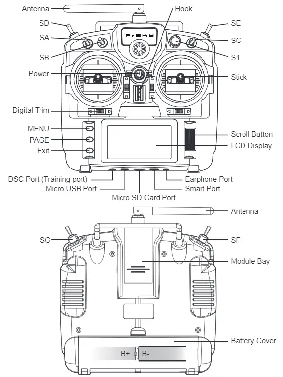
Step 6: Set Failsafe mode
There are 4 failsafe modes: No pulse, Hold, Custom and receiver. No Pulse: on loss of signal the receiver produces no pulses on any channel.
Hold: the receiver continues to output the last positions before signal was lost.
Custom: pre-set to required positions on lost signal.
Receiver: set the failsafe on the receiver (see receiver instructions) in ACCESS Protocol.
Step 7: Range
Range refers to Taranis X9 Lite/Taranis X9 Lite S range check mode. A pre-flight range check should be done before each flying session. Move the cursor to [Range Check] and press the Scroll Button. In range check mode, the effective distance will be decreased to 1/30. Press the EXIT to exit.
About OpenTX:
Scroll Button
To navigate menus or widgets, roll the button to left or right as navigation.
FLYING SAFETY
Warning:
To ensure the safety of yourself and others, please observe the following precautions. Have regular maintenance performed. Although your X9 Lite protects the model memories with non-volatile EEPROM memory (which does not require periodic replacement) and of a battery, it still should have regular check-ups for wear and tear. We recommend sending your system to your FrSky Service Center annually during your non-flying-season for a complete check-up and service.
Battery
Using a fully charged battery (DC 6.0~8.4V). A low battery will soon die, causing loss of control and a crash. When you begin your flying session, reset your transmitter’s built-in timer, and during the session pay attention to the duration of usage. Also, if your model used a separate receiver battery, make sure it is fully charged before each flying session.
Stop flying long before your batteries become over discharged. Do not rely on your radio’s low battery warning systems, intended only as a precaution, to tell you when to recharge. Always check your transmitter and receiver batteries prior to each flight.
Where to Fly
We recommend that you fly at a recognized model airplane flying field. You can find model clubs and fields by asking your nearest hobby dealer.
At the flying field
- Pull throttle stick to idle position, or otherwise disarm your motor/engine.
- Turn on the transmitter power and allow your transmitter to reach its home screen.
- Confirm the proper model memory has been selected.
- Turn on your receiver power.
- Test all controls. If a servo operates abnormally, don’t attempt to fly until you determine the cause of the problem.
- Start your engine.
- Complete a full range check.
- After flying, bring the throttle stick to idle position, engage any kill switches or otherwise disarm your motor/ engine.
Updates
FrSky is continuously adding features and improvements to our radio systems. Updating (via USB Port or the Micro SD card) is easy and free. To get the most from your new transmitter, please check the download section of the FrSky website for the latest update firmware and guide for adjusting your sticks. (www.frsky-rc.com)
FrSky Electronic Co., Ltd.
www.frsky-rc.com
Contact us: [email protected]
Add: F-4,Building C, Zhongxiu Technology Park, No.3 Yuanxi Road, Wuxi, 214125, Jiangsu, China
Technical Support: [email protected]
Instruction Manual for FrSky Scout
VS600 BLACK/VS600 RED
Introduction
Thank you for purchasing the FrSky Scout VS600 BLACK/VS600 RED video transmission device. A simple and clean design, equipped with switchable power output and operating band and channel. Paired with a FrSky radio transmitter, the parameters can be adjusted conveniently through the grains. Lua script. In addition, it has a built-in microphone that transmits audio. To fully enjoy all the features of this device please thoroughly read the instructions below to set up the device.
Overview
Specifications
| Model Name | L*W*H(mm) | Weight(g) | Available Channel | Operating Voltage |
| Scout VS600 BLACK | 31*24*4.9 | 4 | 48CH | 2-6S |
| Scout VS600 RED | 31.5*23.6*4.5 | 4.2 | 48CH | 2-6S |
- Transmission Frequency: 5.8 GHz
- Transmission Power: <0.01mW (pit mode) /25mW/200mW/600mW
Features
- Support S.Port
- Support inverted S.Port
- Built-in microphone
- Adjustable RF power
- Support set parameters by gTrans.lua /Button /FreeLink(PC)/FreeLink App.
Transmission Frequency
| FR fMHzCH | CH1 | CH2 | CH3 | CH4 | CH5 | CH6 | CH7 | CH8 |
| A | 5865 | 5845 | 5825 | 5605 | 5785 | 576S | 5745 | 5725 |
| B | 5733 | 5752 | 5771 | 5790 | 5809 | 5828 | 5847 | 5866 |
| C | 5705 | 5685 | 5665 | 5645 | 5885 | 5g0S | 5925 | 5945 |
| D | 5740 | 5760 | 5780 | 5600 | 5820 | 5840 | 5860 | 5880 |
| E | 5658 | 5695 | 5732 | 5769 | 5806 | 5843 | 5880 | 5817 |
| F | 5362 | 5389 | 5436 | 5473 | 5S10 | 5547 | 5584 | 5612 |
LED State
| LED | Green | Red | Blue |
| Indication | RF Power | Band | Channel |
The Scout VS600 BLACK/VS600 RED has a green LED which indicates the RF power. As you press the button key, the LED will flash, indicating the corresponding RF power level.
The Scout VS600 BLACK/VS600 RED has a red LED which indicates the frequency band. As you press the button key, the LED will flash, indicating the corresponding frequency band.
The Scout VS600 BLACK/VS600 RED has a blue LED that indicates the channel. As you press the button key, the LED will flash, indicating the corresponding channel.
Configuration method
1.Manual configuration (by the Button )
Press the button for (3s) to enter the power/channel/frequency selection mode, press the button for (3s) again to switch between power/channel/frequency.
| Greed LED | Red LED | States | Operation |
| On | On | Channel setting mode | Press the BUTTON (1.5S) to change the channel |
| Off | On | RF Power setting mode | Press the BUTTON (1.5S)
to change the RF Power |
| On | Off | Frequency Band setting mode | Press the BUTTON (1.5S)
to change the Frequency Band |
Note: When setting Channel /Frequency band/RF Power, please strictly follow local laws and regulations.
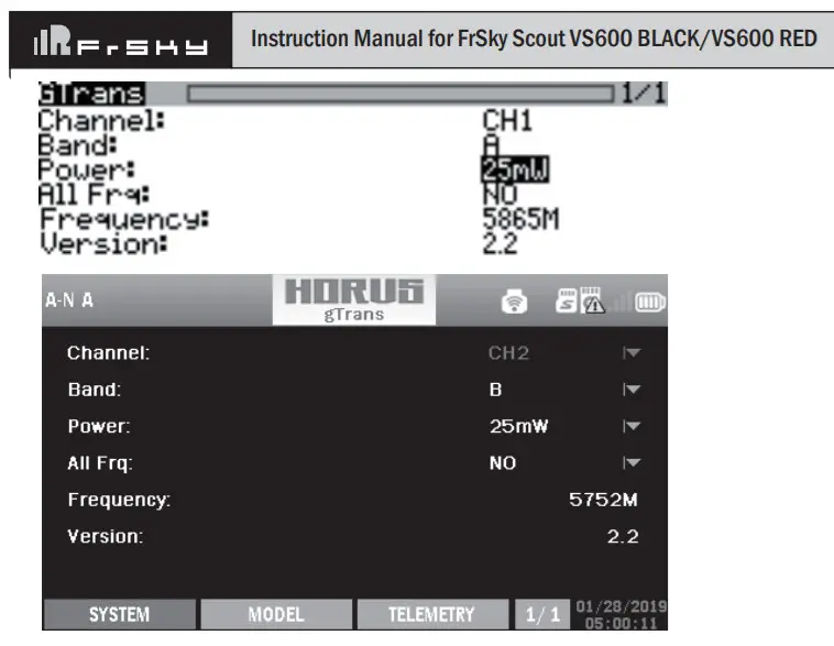
2. The script configuration
Channel, Operating Band, and Operating Power can be set through the transmitter.Run the gTrans.lua which is
on the SD card and start configuration.
The interface is below.
Note: Please running Scout VS600 BLACK/VS600 RED before running the script.
3. FreeLink(PC) configuration
Channel, Operating Band, and Operating Power can be set through the FreeLink(PC). Connect Scout VS600 BLACK/VS600 RED to STK or S.Port AirLink S to the computer and configure parameters with FreeLink(PC).
The interface is below.
4.FreeLink App configuration
Channel, Operating Band, and Operating Power can be set through the FreeLink App. Connect Scout VS600 BLACK/VS600 RED to the S.Port AirLink S and configure parameters with FreeLink App in the mobile terminal.
Pit Mode
A feature introduced with Scout VS600 BLACK/VS600 RED is Pit Mode, It allows the user to power up their video transmitter during race events without interfering with other users and still have the ability to change VTX settings and perform tests mode features all the functions under Normal mode other than operating power.
FCC STATEMENT
- This device complies with part 15 of the FCC Rules. Operation is subject to the following two conditions:
(1) This device may not cause harmful interference.
(2) This device must accept any interference received, including interference that may cause undesired operation. - Changes or modifications not expressly approved by the party responsible for compliance could void the user’s authority to operate the equipment.
Note: This equipment has been tested and found to comply with the limits for a Class B digital device, pursuant to part 15 of the FCC Rules. These limits are designed to provide reasonable protection against harmful interference in a residential installation. This equipment generates uses and can radiate radio frequency energy and, if not
installed and used in accordance with the instructions, may cause harmful interference to radio communications. However, there is no guarantee that interference will not occur in a particular installation. If this equipment does cause harmful interference to radio or television reception, which can be determined by turning the equipment off
and on, the user is encouraged to try to correct the interference by one or more of the following measures:
- Reorient or relocate the receiving antenna.
- Increase the separation between the equipment and receiver.
- Connect the equipment into an outlet on a circuit different from that to which the receiver is connected.
- Consult the dealer or an experienced radio/TV technician for help.
FrSky is continuously adding features and improvements to our products. To get the most from your product, please check the download section of the FrSky website www.frsky-rc.com for the latest update firmware and manuals.
FrSky Electronic Co., Ltd
www.frsky-rc.com
Contact us: [email protected]
Add: F-4, Building C, Zhongxiu Technology Park, No.3 Yuanxi Road, Wuxi, 214125, Jiangsu, China
Technical Support: [email protected]