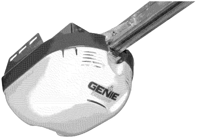

GENIE Excelerator Garage Door Opener

SAFETY INFORMATION
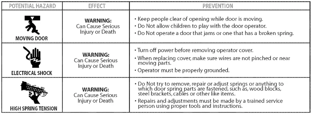
Garage Doors are heavy objects that move with the help of springs under high tension and electric opening equipment. Since moving objects, springs under tension, and electric opening equipment may cause injuries, your safety and the safety of others depend on you reading and understanding the information in this manual. If you have garage door related questions or do not understand the information presented, call your nearest Genie Factory Authorized Dealer listed at www.geniecompany.com
IMPORTANT INSTALLATION INSTRUCTIONS
To REDUCE THE RISK OF SEVERE INJURY OR DEATH:
- READ AND FOLLOW ALL SAFETY, INSTALLATION AND OPERATION INSTRUCTIONS. If you have any questions or do not understand an instruction, call your service representative.
- Do Not install operator on an improperly balanced door. An improperly balanced door could cause severe injury. Repairs and adjustments to cables, spring assembly, and other hardware must be made by a trained service person using proper tools and instructions.
- Remove all ropes, and disable all locks connected to the door before installing operator.
- Install door operator 7 feet or more above the floor. Mount the emergency release knob 6 feet above the floor.
- Do Not connect the operator to the source of power until instructed to do so.
- Locate the control button:
- Within sight of door.
- At a minimum height of 5 feet, so small children cannot reach it.
- Away from all moving parts of the door.
- Install the entrapment WARNING label next to the wall button or console. Install the emergency release tag on, or next to, the emergency release
- The operator must reverse when the door contacts a 1-1/2 inch high object on the floor at the center of the doorway. This is about the size of a 2″ x 4″ board laid flat.
SAFETY FEATURES
Safe-T-Beam (STB) Non-Contact Reversing System:
Places an invisible beam across door opening, that reverses the door during down travel to the fully open position if anything passes through beam.
Safe-T-Reverse Contact Reversing System:
Automatically stops and reverses a closing door within 2 seconds of contact with an object.
Safe-T-Stop Timed Reversed System:
Automatically opens a closing door, if door does not close within 30 seconds.
Force Guard Control:
Used to set the force required for opening and closing door. For maximum safety, set the minimum force required to fully open and close door.
Automatic lighting System:
Two light bulbs up to 60 Watts max. each, are used for safer entries and exits. The light turns on when door is activated and automatically turns off 4.S minutes later.
Manual Emergency Release:
Allows the garage door to be opened or closed manually for emergencies or maintenance.
PRE-INSTALLATION CHECKLIST
This Opener includes parts and supplies needed to install in most garages and connect to most garage doors. There are many variations of garages and garage doors. A few additional parts and supplies may be needed to install Opener into your garage and connect to your garage door. While checking items listed below, note any additional items you will need.
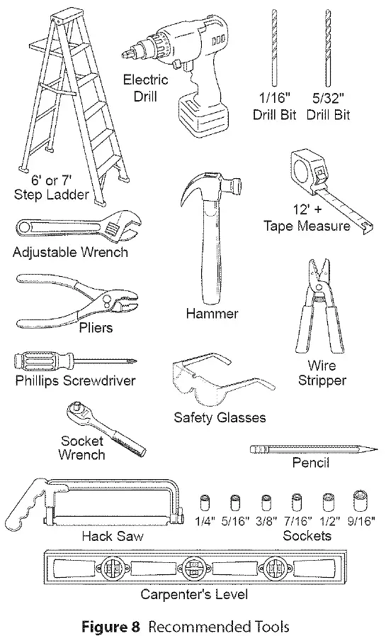
Tools used in this section:
- 12’+ Tape Measure
- Pencil
- Ladder
- Level
NOTE: The Accelerator Opener is equipped with an automatic Garage Door Balance Detection system on page System. 27.
Check following items before assembling Opener
Step 1: CHECK DOOR CONDITION AND THICKNESS
Check condition of vertical stile in center of door, and its connection to door’s top and bottom beams.
- If door frame is nailed together and not a solid connection, door frame must be braced or reinforced before installing Opener.
- If door is “lightweight” (made with frame and skin – not solid),door (including door frame) must be braced or reinforced before installing Opener.
- A door opener reinforcement bracket may also be needed to connect garage door to Opener’s Door Bracket. This Opener is designed for installation on a properly braced sectional door or solidly braced one-piece door.
- Contact your Genie Factory Authorized Dealer or dealer of your garage door for any necessary bracing and a door opener reinforcement bracket (if needed) before proceeding.
- E If you have a wooden door, measure door’s thickness. (1/4″ x 2″) Lag Screws are included for installing Door Bracket onto door. If your door is less than 2″thick, brace door or use shorter Door Bracket Lag Screws (1/4″ x 11/4″ – not included)
Step 2: CHECK GARAGE DOOR ALIGNMENT, OPERATION, AND BALANCE
- Raise door, check alignment and see if it moves freely (Figure 1 ). If door appears out of alignment, binds, or does not move smoothly, contact a Genie Factory Authorized Dealer or dealer of your garage door for repairs and adjustments to door mechanism.
- Raise door to 3′ – 4′ above ground and carefully let go. Door should stay stationary. Slight movement is acceptable. More than slight movement means door is out of balance. Contact a Genie Factory Authorized Dealer or dealer of your garage door for repairs and adjustments to door mechanism.
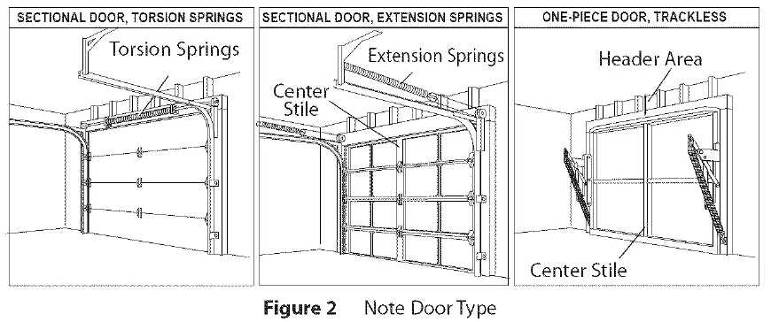
- Check door type. Make a note of whether it is a sectional or a one-piece door (Figure 2).
Step 3: MEASURE GARAGE DOOR HEIGHT
Measure garage door height (7′-6″, 8′-0″, or taller) with tape measure.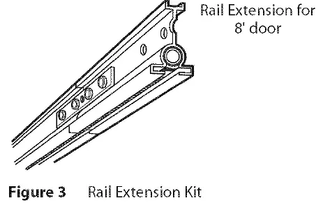
- If door height is 7′-6″ or less, continue with Check Step 4.
- If your door height is above 7′-6″, make sure your rail is long enough to open the garage door. If there is any question contact your Customer Service Representative at 1-800-35-GENIE.
Step 4: CHECK DOOR HEADER AREA
Note: The header is a heavily reinforced section of the wall just above the top of the garage door opening.
- Find vertical center line of door and header:
- Close door.
- Measure door width at top.
- Mark a point at center of door and on header directly above door. Draw a center line to connect points.
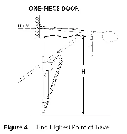
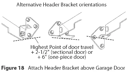
- Find Header Bracket mounting height (Figure 4):
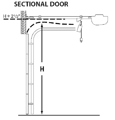
(Do not attach Header Bracket).- Raise door, watching top edge of door and stop door when its edge reaches its highest point.
- Measure distance (“H”) from top edge of door to floor.
- For sectional doors, add 2-1 /2″ to “H”. Mark a point on center line. Bottom of Header Bracket will be installed here.
- For one-piece doors, add 6″ to “H”. Mark this point on center line. Bottom of Header Bracket will be installed here.
- For both types of doors:
- If the ceiling in your garage is so low that there is not at least a 3″ space above the Header Bracket mounting point, contact a Genie Factory Authorized Dealer.
- If a door spring is in the way, place the Header Bracket avove the spring. Do Not move the door spring.
- Check wall for a stud or a solid header at your mark:
- If location is above Header, a 2″ x 6″ board must be screwed to studs beside your mark with at least two Lag Screws and Flat Washers (not provided).
- Transfer your mark to new mounting board.
Step 5: CHECK POWER HEAD MOUNTING AREA
Check ceiling or space above where Opener Power Head will be mounted (Figure 5):
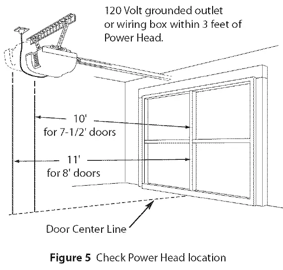
- Measure from garage door center line mark toward rear of garage:
- Approximately 1 O’ back if garage has a 7′ 6″ door.
- Approximately 11′ back if garage has an 8′ O” door.
- Approximately 13′ back if garage has an 1 O’ O” door.
- Approximately 14′ back if garage has an 12′ O” door.
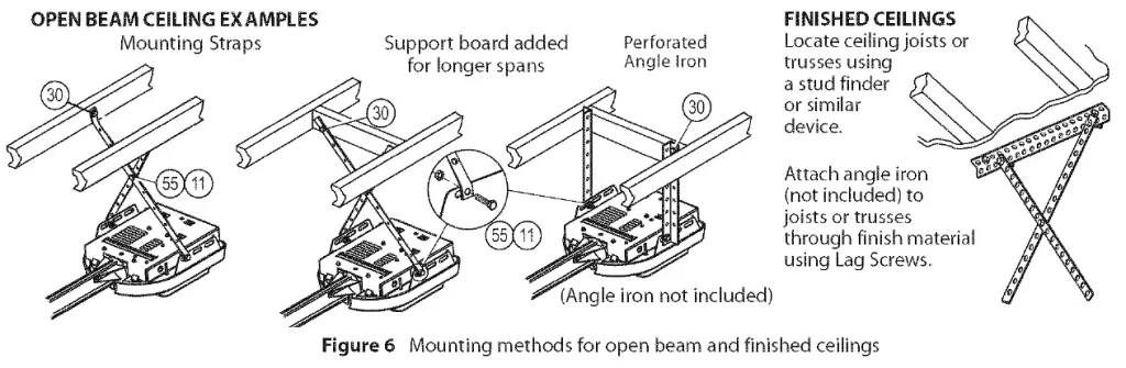
NOTE: Mounting Straps are included to attach the Opener to most garage ceilings. Garage construction varies widely. Additional mounting straps or angle iron may be needed for your installation.
- Find location of ceiling joist or truss above where Opener Power Head will be and estimate type and quantity of materials needed for your installation (Figure 6).
Step 6: CHECK CEILING FOR GROUNDED POWER SOURCE
- Check that there is a 15 Amp 120Volt grounded electrical outlet or grounded permanent wiring box (per building code) within 3′ of Opener Power Head:
- If not, an outlet or wiring box must be installed. Contact a licensed electrician for installation.
- If building codes require permanent wiring, Power Head must be partially disassembled to install appropriate wiring in place of Power Cord. See page 19
NOTE: Permanent wiring must be installed by a licensed Electrician. Not all Genie Factory Authorized Dealers are Licensed Electricians. Contact someone who is a Licensed Electrician.
Step 7: CHECK SAFE-T-BEAM MOUNTING BRACKET LOCATION
-
- enie Factory Authorized Dealer or through Accessories Order Form on pages 31/32).
STEP 8: RECOMMENDED TOOLSCheck for wood garage jamframe,b, or masonry at mounting location (6″ above floor) with attachment tabs facing away from garage door (Figure 7).
- If you cannot mount Safe-T-Beam® Mounting Bracket to wood frame:
- Concrete screws and concrete anchors (not included) must be used to mount Brackets on masonry with attachment tabs facing away from garage door.
- Safe-T-Beam® Mounting Bracket Extensions may be used (not included – available from a G
- Tools (Figure 8):
- Additional easier:
- Slotted and Philips tools to make screw-driver bits
- Stud finder
Step 9: REMOVE EXISTING GARAGE DOOR LOCKS
Check that the garage door locks, rope, and T-Handles are removed from the garage door before starting the installation.
- If your garage does not have a separate entry door, it is highly recommended to install a Genie Emergency Release Kit (GER-2). Emergency Release Kit lets you open garage door from outside if there is a power failure. (Please see Accessories Order Form on pages 31 /32.)
Before going further, get any items and tools needed for your installation
- Safe-T-Beam® Sensor Mounting Bracket Extensions (dealer) 0 Garage door opener reinforcement bracket (dealer)
- Garage door frame reinforcement brackets, screws, bracing or reinforcement kits (dealer)
- Lag Screws (11/4″) for a wood door less than 2″ thick (store)
- Electrical outlet and/or wiring (supplied by a licensed electrician)
- Excelerator Extension Kit (for 8′ garage doors) (store)
- Sufficient angle iron or strapping for hanging Power Head (store)
- Two 60 Watt light bulbs (Rough service bulbs recommended)(store)
- GER-2 Emergency Release Kit for entry during power failure
- Wood for header, ceiling, and/or door bracing reinforcement (if needed)
- Masonry fasteners for Safe-T-Beam® Bracket installation, (if needed)
- Masonry drill bit (if needed)
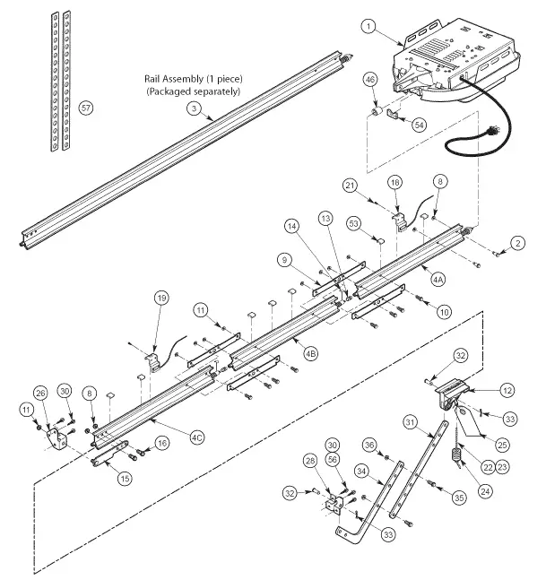
POWER HEAD ASSEMBLY EXPLODED VIEW
POWER HEAD ASSEMBLY PARTS LIST
| Item | Part Name | ||
| 1A | Lens | ||
| 1B | Top Plate Assembly | ||
| lC | Light Socket (2 | ||
| 1D | Motor Assemblv | ||
| 1E | Cover | ||
| 1G | Motor Drive Board | ||
| 1H | Controller Bo
ard |
||
| ex Head | |||
| 1L | No. 8-32 x 1″ Phillips Screw | ||
| 1M | No. 8-32 x 3/8″ Slotted Hex Head Screw | ||
| 1p | Power Cord |
EXCELERATOR HARDWARE EXPLODED VIEW
NOTE:alledOpener will not function unless Safe-T-B® Syseamtem is inst and Force Controls aproperly re set.
One-Piece Rail Asseembly ( Pro only) for 1 O’ or 12′ includes:
- Special “Close” Limit Switch with longer Wires .
- 96″ Emergency Rlease Cord (yellow) .
- Rail Support Kit.
GARAGE DOOR OPENER ASSEMBLY
CONNECT RAIL TO POWER HEAD
Open Blue Bag
- Turn Powr Heeown and ad erupside dplace on a flat level surface.
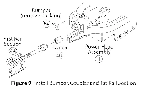
- Install Bump (Figure 9).
- Install Coupler on Motor Shaft (Figure 9).ead. Connect wi
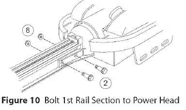
CAUTION:The Rail Section toner OpePower Hth 2 (1/4″-20) (yellow) Hex Head Shoulder Bod 2 (1/4″ -20) lts anHex Serrated Flange Nuts (Figure 10). Finger-tighten until later.
- If you have a 1-piece rail unit, skip Assembly Step 2.
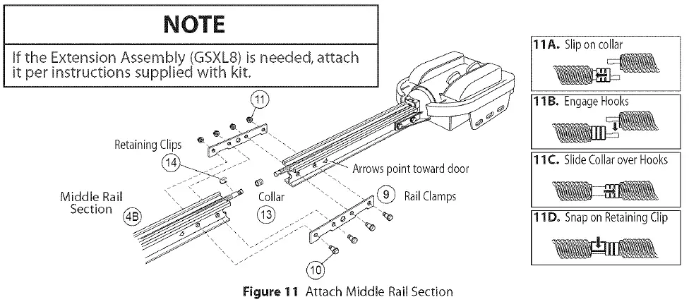
INSTALL REMAINING RAIL SECTIONS
- Arrange arrows on Rail Sections to point in same direction and away from Power Head:
- Push Middle Drive Screw out about 2″ toward Power Head.
- Slide Collar over Middle Drive Screw Hook (Figure 11A).
- Turn Middle Screw by hand to align Drive Screw Hooks between First and Middle Rail Sections.
- Latch two Hooks together and slide Collar over them (Figure 11 Bl and (Figure 11 C).
- Snap Clip on Drive Screw next to Collar (Figure11 D).
- Attach Middle Rail Section to First Rail Section, using 2 Rail Clamps, 4 (S/16″-18) HAttach End Rail Section to Middle Rail Section following procedures in step A & B.
- ex Shoulder Bolts, and 4 (S/16″-18) Hex Head Serrated Flange Nuts onto Bolts (Figure 11 ). (Middle Rail Section looks the same on both ends.
Install Magnetic Carriage Assembly Onto Rails
- Place Magnetic Carriage Assembly Lever in “release” position.
- Slide Magnetic Carriage Assembly into slot on End Rail Section with arrow pointing away from the Power Head (Figure 12).
Install Rail Strap To End Rail Station
- Attach Rail Strap to End Rail Section with 2 (1 /4″-20) Hex Head Bolts and 2 (1/4″-20) Serrated Flange Hex Nuts (Figure 13).
- Tighten snugly but Do Not over-tighten.
Align Rail Station
- Align all Rail Sections so Magnetic Carriage Assembly can slide freely along length of Rail.
- Securely tighten all fasteners now. Do Not over-tighten.
Open Green Bag Parts
- Turn Opener right side up and support Power Head to avoid damaging the Light Bulb Sockets.
- Uncoil Limit Switch Wires and retain Twist Ties.
- Place Switches on Rail with arrows pointing away from Power Head (Figure 14).
- Place Close Limit Switch (Brown Wire) 1 S” from Rail Strap. Insert (#8-32 x 1 “) Hex Head Screw into Switch hole and finger-tighten until later.
- Place Open Limit Switch (White Wire) 15″ from Power Head. Insert (#8-32 x 1 “) Hex Head Screw into Switch hole and finger-tighten until later.
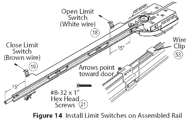
- Lay Wires in channel on top of Rail and secure with Wire Clips (Figure 14).
- Coil and bundle excess Limit Switch Wires on top of Power Head with Twist Ties. Leave just enough Wire to reach Terminals on back of Power Head (Figure 14).
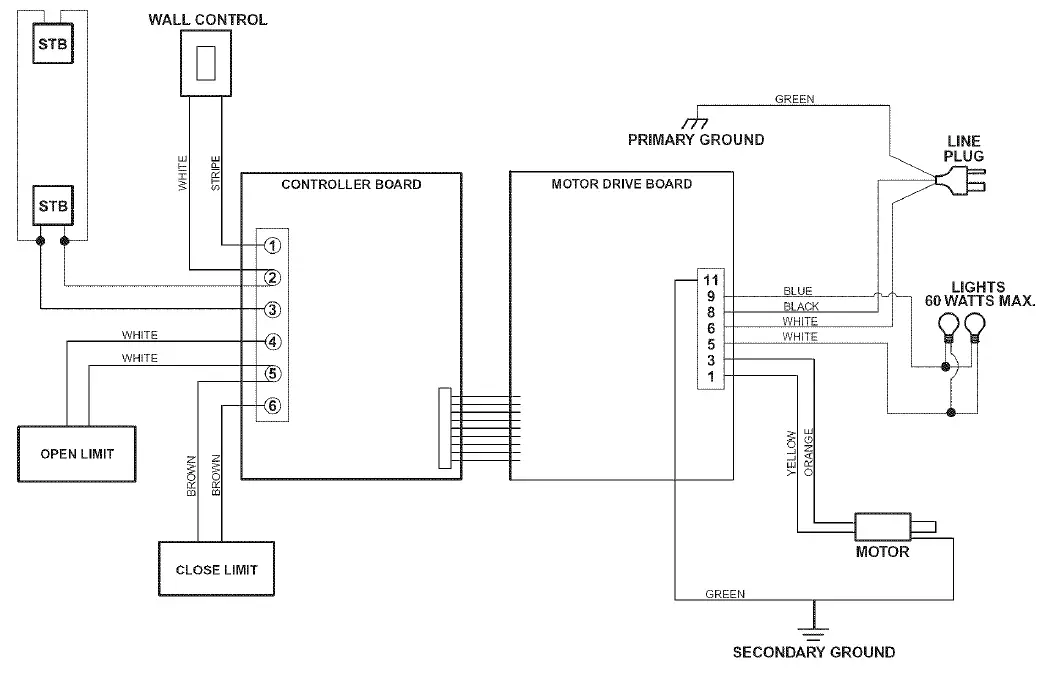
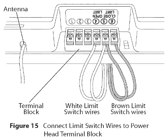
- Turn Opener upside down, and connect Limit Switch Wires to Power Head Terminal Block (Figure 15):
- Terminal 4: OPEN Limit Switch Wire (white).
- Terminal 5: OPEN Limit Switch Wire (white) and CLOSE Limit Switch Wire (brown).
- Terminal 6: CLOSE Limit Switch Wire (brown).
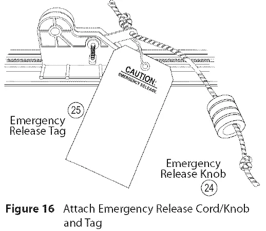
ATTACH EMERGENCY RELEASE KNOB, CORD, AND TAG
- Tie overhand knot at one end of Emergency Release Cord.
- Thread opposite end of Cord through Knob and hole in Magnetic Carriage Assembly Release Lever (Figure 16).
- Tie overhand knot at this end of Emergency Release Cord.
- Attach Emergency Release Tag to Magnetic Carriage Assembly Release Lever.
RECORD OPENER MODEL AND SERIAL NUMBER
Please note the following information so it is available if you need to call us:
Date purchased: ——————————-
Serial number (Figure 17): ——————————-
Model number (Figure 17):——————————-
Dealer Name: ——————————-
Dealer Address: ——————————-
City: ——————————-
State: ——————————-
Zip: ——————————-
Phone: ——————————-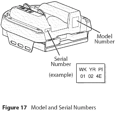
NOTE: Please keep original or photocopy of your sales receipt with this manual for future reference should service ever be required.
GARAGE DOOR OPENER INSTALLATION
NOTE: For lightweight garage doors, make sure you have installed the proper reinforcement (See Check Door Condition and Thickness on page 3).
INSTALL HEADER BRACKET
CAUTION:
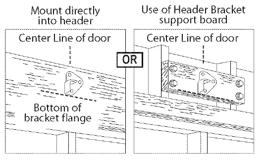
- The Header Bracket must be fastened to the garage framing. Do Not fasten the Header Bracket to drywall, particle board, plaster, or other such material.
- It may be necessary to attach a 2″ x 6″ board across the wall studs above the door header to serve as a mounting plate for the Header Bracket. The Bracket can then be mounted at the proper location and have sufficient support.
- If a door spring is in the way, place the Header Bracket above the spring. Do Not move the door spring.
- If needed, attach a 2″ x 6″ board (Figure 18) (also see page 4) with at least two (four is recommended) Lag Screws and Flat Washers (not supplied).
- Attach Header Bracket to header at mark above door.
Open Orange Parts Bag
NOTE: Mounting variations are shown in Figure 18. Any of these may be used depending on space. However, it is critical that the point where the Rail attaches to the Header Bracket be on the center line of the door.
- Mark 3 hole positions.
- Drill 3 (5/32″) pilot holes.
- Attach Header Bracket with 3 (1/4″ x 2″) Lag Screws.
INSTALL GARAGE DOOR BRACKET
CAUTION: Doors made of masonite, lightweight wood, fiberglass, metal, or other lightweight materials must be properly braced before mounting door Opener.
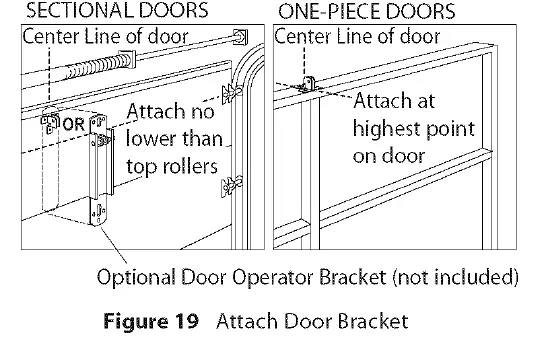
For sectional doors:
- Place Door Bracket on door center line, no lower than top roller, and mark holes (Figure 19).
- Attach Door Bracket:
- For metal doors, use 3 (1 /4″ -20 x 3/4″) Self-Drilling Screws (provided).
- For wood doors, use 3 (1/4″ x 2″) Lag Screws or 3 (1/4″ x 11/4″) Lag Screws (not provided).
NOTE: Before installing, check length of the included Lag Screws vs. the thickness of your garage door. For doors thinner than 2″, use 11/4″ Lag Screws. Check door condition and thickness. See page 3.
For one-piece doors:
- Position Door Bracket on door’s center line, as high as possible or on top of door.
- Attach Door Bracket:
- For metal doors, use 3 (1/4″ -20 x 3/4″) Self-Drilling Screws.
- For wood doors, use 3 (1/4″ x 2″) Lag Screws.
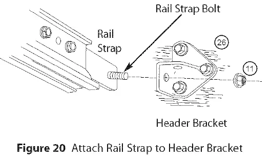
ATTACH RAIL TO HEADER BRACKET
- While supporting the Power Head, place threaded end of Rail Strap Bolt through Header Bracket hole (Figure 20).
- Attach (5/16″-18) Flange Nut to Rail Strap Bolt. Finger-tighten until later.
NOTE:
- Little effort is required to turn the Force Adjusting Knobs.
- If the door stops moving while opening or closing, adjust the Open Force or Close Force Controls slightly clockwise (to slightly increase the force) and retry the step.
- The Open Force and Close Force Controls are to be set to the minimum force necessary to ensure the door smoothly opens fully and closes completely.
- The garage door will move slowly the first time it runs, until the Opener “learns” the type of door.
- Ensure the Magnetic Carriage Assembly is engaged and is between the two Limit Switches before operating the Opener.
- To protect your new investment, your Excelerator® is equipped with a Timer and Cycle Counter which work together to prevent any chance of heat damage to electrical circuits caused by too many cycles in too short a time. If your Opener suddenly stops responding to the Wall Console – Do Not Unplug the Unit – simply wait 10 minutes for the Timer/Cycle Counter to reset itself and try again.
- Unplugging the unit will prevent the Timer/Cycle Counter from resetting.
- The door must contact the 2″ x 4″ board before the Carriage activates the Close Limit Switch. If not, readjust the Close Limit Switch.
- Each Remote Control must be programmed separately.
- The Remote Controls will not cause the door Opener to close the garage door if the Safe-T Beam® System is malfunctioning.
- When programmin the Remote Controls, they must be at least 24′ from the Antenna Wire.
- If the red Learn Indicator Light blinks approximately 4 times per second, programming has stopped. If programming has stopped, repeat the above steps.
- Each Button on a 2 or 3 Button Remote Control is for a different Opener. You cannot use more than one Button per Remote, per Opener.
- A maximum of seven Remote Controls or Wireless Keypads can be stored into the Receiver at one time. If a Remote Control becomes lost, or if you want to delete a Remote Control or Wireless Keypad, see”To Erase All Receiver Memory.”
WARNING: TO REDUCE THE RISK OF SEVERE INJURY OR DEATH
- READ AND FOLLOW ALL
- Never let children operate or play with the Door Keep the Remote Control away from children.
- Always keep the moving door in sight and away from people and objects until the door is completely NO ONE SHOULD CROSS THE PATH OF THE MOVING DOOR.
- NEVER GO UNDER A STOPPED, PARTIALLY OPEN
- Test Opener The door MUST reverse on contact with a 1-1/2″ high object (or a 2″ x 4″ board laid flat) at the center of the doorway on the floor. After adjusting either the Force or the Limit of travel, retest the Door Opener. Failure to adjust the Opener properly may cause severe injury or death.
- When possible use the Emergency Release only when the door is Use caution when using this Release with the door open. Weak or broken springs are capable of increasing the rate of door closure and increasing the risk of severe injury or death.
- KEEP GARAGE DOORS PROPERLY See Owner’s Manual. An improperly balanced door increases the risk of severe injury or death. Have a Genie Factory Authorized Dealer make repairs to cables, spring assemblies, and other hardware.