![]() 7130-18-BT Bath Fan With Bluetooth
7130-18-BT Bath Fan With Bluetooth
Speaker And LED Light
User Manual
![]() Questions, problems, missing parts? Before returning to the store, call our customer service department at 1-877-319-3757, 7:30 a.m. – 4:30 p.m., CST, Monday – Friday.
Questions, problems, missing parts? Before returning to the store, call our customer service department at 1-877-319-3757, 7:30 a.m. – 4:30 p.m., CST, Monday – Friday.
READ AND SAVE THESE INSTRUCTIONS
U.S. Pat. No. 9,398,357
The BLUETOOTH fiword mark and logos are registered trademarks owned by BLUETOOTH SIG, Inc. and any use of the said mark by Homewerks Worldwide is under license. Other trademark and trade names are those of their respective owners.
Homewerks.com
PRODUCT SPECIFICATIONS
| Airflow: 80 CFM | LED light power consumption: 13W |
| 120V, 60Hz | LED light brightness: 600 lumens |
| Duct diameter: 4 in. | LED light color (CCT): 4000K Cool White |
| Sound output: 1.5 sones | Weight: 6.1 lbs. |
| Motor power consumption: 19W |
UL COMPLIANCE
Ventilation Fan Motor Wheel Assembly F is combined into Ventilation Fan Motor Housing F-1 which is mounted into the ceiling opening.
These components comply with UL File 507: section 10.6, section 62.2.3, section 62.4.1, and section 64A.9.
FCC COMPLIANCE
NOTICE: This equipment has been tested and found to comply with the limits for a Class B digital device, pursuant to part 15 of the FCC Rules.
These limits are designed to provide reasonable protection against harmful interference in a residential installation.
This equipment generates, uses, and can radiate radio frequency energy and, if not installed and used in accordance with the instructions, may cause harmful interference to radio communications. However, there is no guarantee that interference will not occur in a particular installation.
If this equipment does cause harmful interference to radio or television reception, which can be determined by turning the equipment off and on, the user is encouraged to try to correct the interference by one or more of the following measures:
- Reorient or relocate the receiving antenna.
- Increase the separation between the equipment and receiver.
- Connect the equipment into an outlet on a circuit different from that to which the receiver is connected.
- Consult the dealer or an experienced radio/TV technician for help.
Changes or modifications made to this equipment not expressly approved by the party responsible for compliance could void the user’s authority to operate the equipment.
PACKAGE CONTENTS
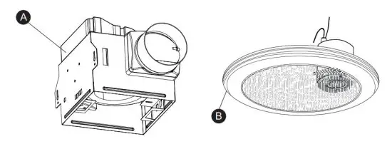
| PART | DESCRIPTION | QUANTITY |
| A | Fan housing | 1 |
| B | Grille with BLUETOOTH® speaker and LED light | 1 |
HARDWARE INCLUDED (not shown actual size)
![]() Wood Screw Qty. 4
Wood Screw Qty. 4
SAFETY INFORMATION
Please read and understand this entire manual before attempting to assemble, operate or install the product.
- Always disconnect the power supply prior to servicing the fan, motor or junction box.
- Follow all local building, safety, and electrical codes as well as NEC (National Electrical Code) and OSHA (Occupational Safety and Health Act).
- Electric Service supply must be 120 volts, 60 hertz.
- This product must properly connect to the grounding conductor of the supply circuit.
- Do not bend or kink the power wires.
- Do not use this fan with any solid-state control device, such as a remote control, dimmer switch, or certain timers. Mechanical timers are not solid-state devices.
- Do not install in a ceiling with insulation greater than R40.
- Ductwork should be installed in a straight line with minimal bends.
- Ductwork size must be the same size as the discharge and should not be reduced. Reducing the duct size may increase fan noise.
- This product is not intended for connection to rigid metal conduit. For use with flexible conduit only.
CAUTION:
- For general ventilating use only. Do not use to exhaust hazardous or explosive materials and vapors.
- Not for use in kitchens.
- To reduce the risk of injury to persons, install the fan at least 7 feet (2.1m) above the floor.
- To reduce the risk of fire and to properly exhaust air, be sure to vent air to the outdoors. Do not vent exhaust air into spaces within walls or ceilings, or into attics, crawl spaces, or garages.
WARNING: To reduce the risk of fire, electric shock, or injury to persons, observe the following:
- Use this unit in the manner intended by the manufacturer. If you have any questions, please call customer service.
- Before servicing or cleaning unit, switch power off at the service panel and lock the service disconnecting means to prevent power from being switched on accidentally. When the service disconnecting means cannot be locked, securely fasten a prominent warning device, such as a tag, to the service panel.
- Installation work and electrical wiring must be done by a qualified person(s) in accordance with all applicable codes and standards, including fire-rated construction.
- Sufficient air is needed for proper combustion and exhausting of gases through the flue (chimney) of fuel burning equipment to prevent back-drafting. Follow the heating equipment manufacturer’s guidelines and safety standards such as those published by the National Fire Protection Association (NFPA), the American Society for Heating, Refrigeration and Air Conditioning Engineers (ASHRAE), and local code authorities.
- When cutting or drilling into the wall or ceiling, do not damage electrical wiring and other hidden utilities.
- To reduce the risk of fire and to properly exhaust air, be sure to vent air to the outdoors. Do not vent exhaust air into spaces within walls or ceilings, or into attics, crawl spaces, or garages.
- If this unit is to be installed over a tub or shower, it must be marked as appropriate for the application and be connected to a GFCI (Ground Fault Circuit Interrupter) —protected branch
- This ventilation fan is intended to be installed at least 28 ft. (1 m) from the showerhead when installing over a bathtub or shower. Installation within a shower stall is not recommended for this unit unless the 3.28 ft. (1 m) distance can be met.
CAUTION: Installation of this unit requires the power to be OFF until installation is complete. If you encounter issues with the unit not powering up, please review the troubleshooting section of the instruction manual.
If you require additional assistance, please call 1-877-319-3757, 7:30 a.m. – 4:30 p.m., CST, Monday – Friday.
DO NOT RETURN TO THE STORE.
PREPARATION
Before beginning the assembly of the product, make sure all parts are present. Compare parts with package contents list and hardware contents. If any part is missing or damaged, do not attempt to assemble, install or operate the product. Contact customer service for replacement parts at 1-877-319-3757, 7:30 a.m. – 4:30 p.m., CST, Monday – Friday.
Tools Required for Assembly (not included): Hammer, Flathead Screwdriver, Wire Connectors, Nails, Duct Tape, Phillips Screwdriver, and Utility Knife or Drywall Saw.
Helpful Tools (not included): Electric Drill, Drill Bits
WARNING: RISK OF ELECTRIC SHOCK! Ensure the electricity to the wires you are working on is shut off. Either remove the fuse or turn off the circuit breaker before removing the existing bath fan or installing the new one.
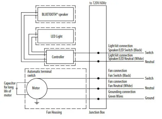
Before removing your current ventilation fan, verify the wall switch box has the required wires necessary for this installation. These wires are power (black) and neutral (white), as shown in the wiring diagram below. If you do not see both of these wires, consult a licensed electrician.
Check area above installation location to be sure that wiring can run to the planned location and that ductwork can be run and Inspect ductwork and wiring before proceeding with the installation.
Before installation, provide inspection and future maintenance access at a location that will not interfere with installation work.
You may need the help of a second person to install this fan; one person on the attic side and one on the room side.
Installation may vary depending on how the previous bath fan was installed. Supplies necessary for the installation of your bath fan are not all included; however, most are available at your local home improvement or hardware store.
DIMENSIONS
| Ceiling Opening (L) |
Ceiling Opening (W) |
Ceiling Opening (H) |
| 7-3/4 in. | 7-1/2 in. | 7-5/16 in. |
| Housing Dimension (L) |
Housing Dimension (W) |
Housing Dimension (H) |
| 7-1/2 in. | 7-1/4 in. | 7 in. |
WIRING
All wiring must be connected for full functionality.
WIRING FOR 1 SWITCH OPERATION
NOTE: For this option cut off the quick connector caps and use standard wire nuts (not included). 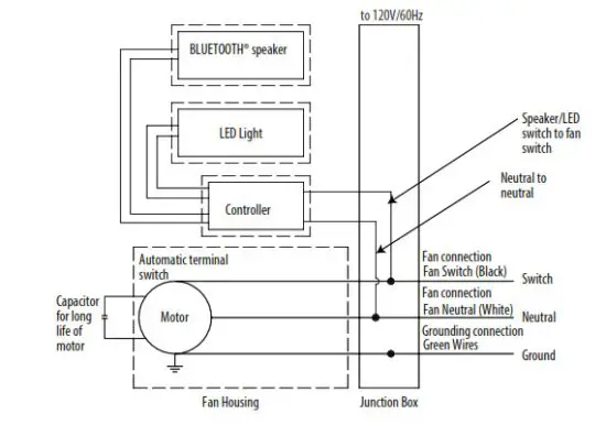
WIRING FOR 2 SWITCH OPERATION
NEW CONSTRUCTION INSTALLATION INSTRUCTIONS
BEFORE INSTALLATION
WARNING: RISK OF ELECTRIC SHOCK! Ensure the electricity to the wires you are working on is shut off. Either remove the fuse or turn off the circuit breaker before removing the existing bath fan or installing the new one.
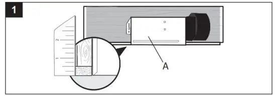
- Place the fan housing (A) next to a ceiling joist.The fan housing (A) should be level and perpendicular to the joist. Allow for the thickness of ceiling board used in your application.
Position the fan housing (A) so the bottom edge of the fan housing (A) is flush with the ceiling board. Do not flush mount the fan housing (A) to the bottom of the joist.
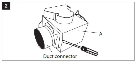
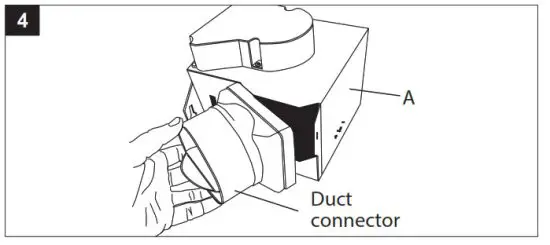
- Before mounting the fan housing (A) to the joist, remove the duct connector for easier access to the mounting hole on that side of the fan housing (A).
Remove the duct connector by inserting a flathead screwdriver between the duct connector and the metal of the fan housing (A), and gently prying the duct connector away from the fan housing (A).
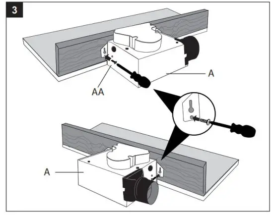
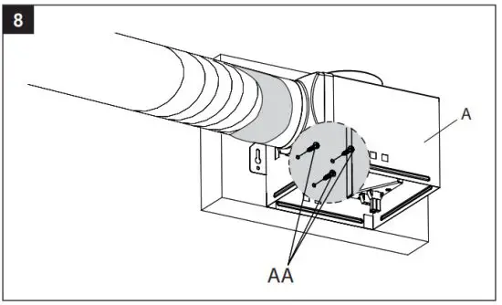
- Mount the fan housing (A) to the joist by inserting wood screws (AA) into the holes indicated on the metal tabs of the fan housing (A). Tighten the wood screws (AA) until the fan housing (A) is firmly secured to the joist.
- Replace the duct connector by hooking the connector on one side of the metal flange on the opening in the fan housing (A) and then pressing on the other side to snap the duct connector into place. Ensure that all four metal flanges on the fan housing (A) are inside the plastic duct connector when it is replaced.
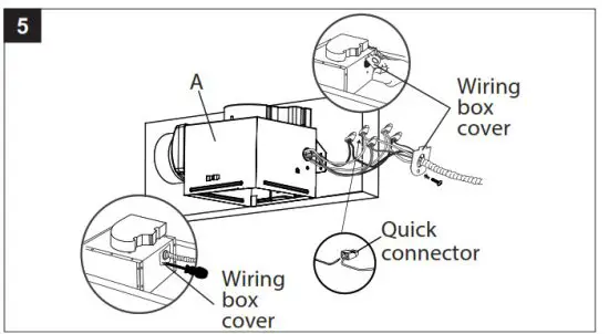
- Remove the wiring box cover from the fan housing (A). Pull the house wires through the hole in the wiring box cover. Using the quick connectors, connect the house wiring from the wall switch to the fan housing (A). 14 AWG is the smallest conductor that should be used for branch-circuit wiring. Please refer to the wiring diagrams on page 5 to ensure proper wire connections are made.
Carefully push the wire connections into the wiring box housing and reattach the wiring box cover.
CAUTION: If your electrical wires do not match the colors listed, consult a licensed electrician to determine what each house wire represents before connecting the fan.
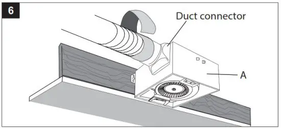
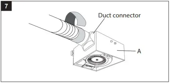
- Connect a 4 in. circular duct to the duct connector on the fan housing (A), securing it with duct tape or a clamp. Vent the duct to the outside.
Finish ceiling work. The ceiling hole should be aligned with the edge of the fan housing (A).
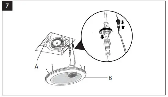
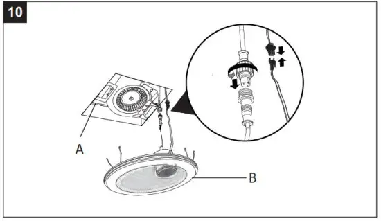
- Join the connectors for the BLUETOOTH® speaker and LED light from the fan housing (A) to the grille (B). After pushing the two gray connectors firmly together, twist the plastic nut to secure the connection. The grille (B) must be connected before turning on the power to the fan.
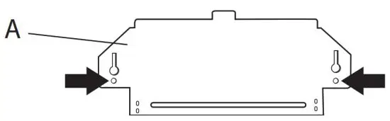
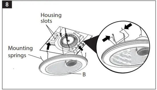
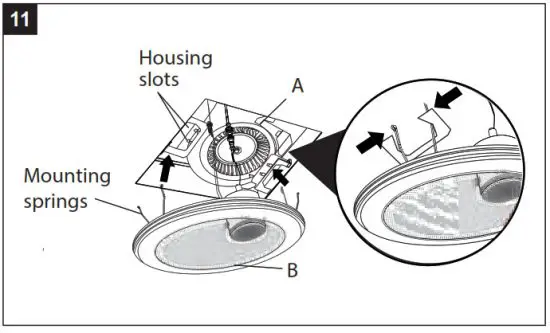
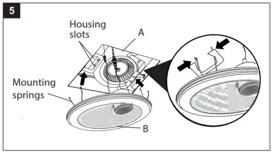
- Attach grille (B) by pinching the mounting springs and inserting them into the narrow rectangular slots in the fan housing (A).
Turn on the power source. Test the unit.
EXISTING CONSTRUCTION INSTALLATION INSTRUCTIONS
Installing the fan housing (A) in an existing building requires an accessible area (attic or crawl space) above the planned installation location, as well as existing duct and wiring.
BEFORE INSTALLATION
WARNING: RISK OF ELECTRIC SHOCK! Ensure the electricity to the wires you are working on is shut off. Either remove the fuse or turn off the circuit breaker before removing the existing bath fan or installing the new one.
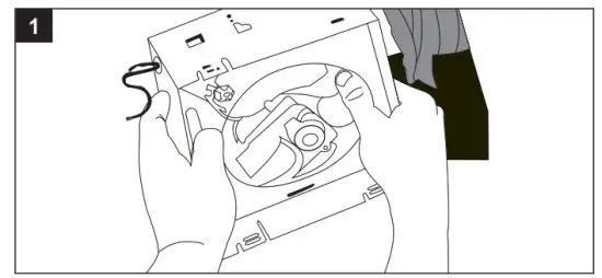
- Remove the existing fan.
- Measure the opening to ensure it is large enough to accommodate the 7-1/2 in. x 7-1/4 in. dimensions of the new fan housing (A).
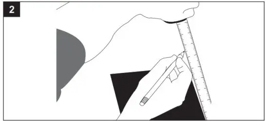
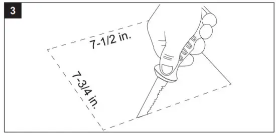
- If this fan is not replacing an old fan, be sure to cut a 7-3/4 in. x 7-1/2 in. opening for the fan housing.
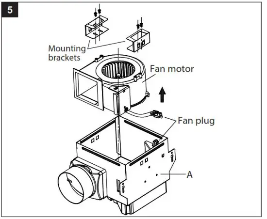
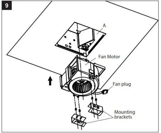
- Detach the two grille mounting brackets by removing the two screws on each bracket.
NOTE: Save the screws for the reinstallation of the mounting brackets
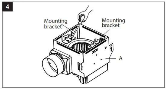
- With the screws removed, slide the grille mounting brackets to the side and remove them from the fan housing (A).
Unplug the three-prong fan plug and pull the black fan motor out of the fan housing (A).
- Remove the wiring box cover from the fan housing (A). Pull the house wires through the hole in the wiring box cover. Using the quick connectors, connect the house wiring from the wall switch to the fan housing (A). 14 AWG is the smallest conductor that should be used for branch-circuit wiring. Please refer to the wiring diagrams on page 5 to ensure proper wire connections are made.
Carefully push the wire connections into the wiring box housing and reattach the wiring box cover.
CAUTION: If your electrical wires do not match the colors listed, consult a licensed electrician to determine what each house wire represents before connecting the fan.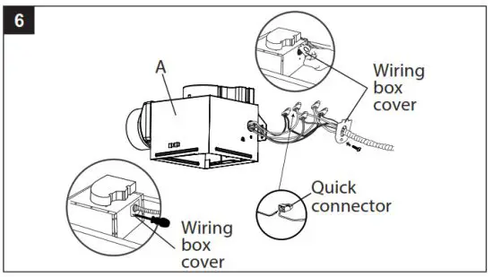
- Connect a 4 in. circular duct to the duct connector on the fan housing (A), securing it with duct tape or a clamp. Vent the duct to the outside.
- With the wiring and duct connected, insert the fan housing (A) into the ceiling hole. Position the fan housing (A) so the bottom edge of the fan housing (A) is flush with the ceiling board. Mount the fan housing (A) to the joist with three wood screws (AA) through the holes in the side of the fan housing (A).
The fan housing (A) must be installed flush with the ceiling board or the grille mounting springs will not be long enough to insert into the slots inside the fan housing (A).
- Plug the three-prong plug on the fan motor back into the fan housing (A). Place the fan motor back into the fan housing (A), aligning the duct with the duct opening in the fan housing (A). Replace the grille mounting brackets and secure with the screws removed earlier.
- Join the connectors for the BLUETOOTH® speaker and LED light from the fan housing (A) to the grille (B). After pushing the two gray connectors firmly together, twist the plastic nut to secure the connection. The grille (B) must be connected before turning on the power to the fan.
- Attach grille (B) by pinching the mounting springs and inserting them into the narrow rectangular slots in the fan housing (A).
Turn on the power source. Test the unit.
PAIRING YOUR BLUETOOTH® DEVICE TO THE SPEAKER
To play your personal music files, you need a wireless BLUETOOTH® device. Set your device to a midrange volume before connecting to the speaker. Follow the instructions that came with your BLUETOOTH® device to make it discoverable or to set it to search for other BLUETOOTH® accessories. This may involve entering a passkey or PIN (Personal Identification Number).
The optimal volume setting for the BLUETOOTH® speaker is 70% or lower. Settings higher than 70% may cause sound distortion.
BLUETOOTH® Connection for One Switch Installation:
Your LED light, speaker and bath fan will be turned on by the same switch:
- After wiring the BLUETOOTH® speaker of your bath fan to your switch, turn the power on. This will put the BLUETOOTH® speaker of the bath fan into connecting mode.
- From the home screen, choose settings > BLUETOOTH® to search for the speaker.
- Choose the Homewerks™ speaker. Enter the passkey or PIN if prompted.
- When pairing is complete, use the BLUETOOTH® speaker to play audio from your device.
- Disconnect the bath fan speaker from your mobile phone or turn off the LED light, speaker and bath fan switch to turn off the BLUETOOTH® connectivity.
BLUETOOTH® Connection for Two Switch Installation:
Your bath fan will be turned on by one switch and your LED light and speaker will be turned on by a second switch:
- After completing the wiring, turn on the switch that has been connected to the LED light and speaker. This will put the BLUETOOTH® speaker of the bath fan into connecting mode.
- From the home screen, choose settings > BLUETOOTH® to search for the speaker.
- Choose the Homewerks™ speaker. Enter the passkey or PIN if prompted.
- When pairing is complete, use the BLUETOOTH® speaker to play audio from your device.
- Disconnect the bath fan speaker from your mobile phone or turn off the LED light, speaker and bath fan switch to turn off the BLUETOOTH® connectivity.
REMINDER:
- This fan does not include a switch.
- For one switch installation, the functions of the LED light, speaker, and fan will turn on and off together.
- For two switch installations, one switch controls the LED light and speaker, and another switch controls the fan.
CARE AND CLEANING
CAUTION: Before attempting to clean the fixture, disconnect the power to the fixture by turning the breaker off or removing the fuse from the fuse box.
See safety information before proceeding. Routine maintenance should be done at least once a year.
- Never use solvents, thinner or harsh chemicals for cleaning the fan.
- Do not allow water to enter the motor.
- Do not immerse metal parts in water.
- Do not immerse resin parts in water more than 140°F.
- Do not immerse the BLUETOOTH® speaker in water.
WARNING: RISK OF ELECTRIC SHOCK!
Ensure the electricity to the wires you are working on is shut off.
Either remove the fuse or turn off the circuit breaker before cleaning.
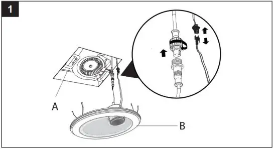
- Remove the grille (B) by squeezing the mounting springs and pulling the grille (B) down from the fan housing (A). Disconnect the connectors to remove the grille (B) from the fan housing (A). Remember to twist the ends of the gray connectors to unlock them before pulling them apart. Wipe grille (B) with a damp cloth.
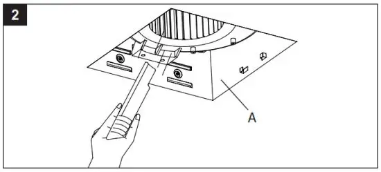
- Remove dust and dirt from the fan housing (A) with a vacuum cleaner.
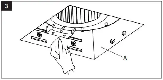
- Wipe the fan housing (A) with a damp cloth and wipe dry.
- Join the connectors for the BLUETOOTH® speaker and LED light from the fan housing (A) to the grille (B). After pushing the two gray connectors firmly together, twist the plastic nut to secure the connection
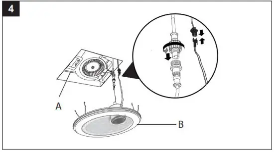
- Attach the grille (B) by pinching the mounting springs and inserting them into the narrow rectangular slots in the fan housing (A).
Turn on the power source.
TROUBLESHOOTING
| PROBLEM | POSSIBLE CAUSE | SOLUTION |
| The fan seems louder than it should. | The CFM is too great for the space. | Be sure the CFM rating on the fan matches the square footage of your room. |
| The damper is damaged or not working properly. | Check the damper to ensure it is opening and closing properly. If the damper has become damaged, please call Customer Service. | |
| The bend in the duct is too close to the fan discharge. | Be sure you do not have any sharp bends in the duct within 18 in. of the fan discharge. | |
| The fan discharge is reduced to fit a smaller duct. | Use the recommended size ducting to reduce fan noise. | |
| The fan body is not attached securely. | Be sure the fan is securely attached to the ceiling joists. | |
| The fan is not clearing humidity from the room. | There is insufficient airflow intake in the room. | Be sure a door or window is slightly ajar or open to allow airflow. The fan is not able to draw air out of the room without enough airflow. |
| There is insufficient CFM. NOTE: Using a tissue is not the correct method for determining if the fan is operating properly. If the fan clears steam from the room within approximately 15 minutes of completing your shower, then the fan is operating properly. |
Be sure the CFM rating of the fan matches the square footage of your room. | |
| BLUETOOTH® device will not pair with the fan. | Another device is already paired. | Make sure BLUETOOTH® signal is tuned off on other devices. |
| Switch will not power up. | There is a wiring issue at the switch or the power is not turned on at the fuse box or circuit breaker |
Check the wiring diagram on page 5 and confirm the wiring is correct. Verify the power is turned on. |
FAN – LIMITED 3-YEAR WARRANTY
If the fan fails due to a defect in materials or workmanship at any time during the first three (3) years of ownership, the manufacturer will replace it free of charge, postage-paid at their option. This warranty does not cover products that have been abused, altered, damaged, misused, cut or worn. This warranty does not cover use in commercial applications. Use only manufacturer-supplied genuine warranty repair replacement parts to repair this fan. Use of non-genuine repair parts will void your warranty. The manufacturer DISCLAIMS all other implied or expresses warranties including all warranties of merchantability and/or fitness for a particular purpose. As some states do not allow exclusions or limitations on an implied warranty, the above exclusions and limitations may not apply. This warranty gives you specific legal rights, and you may have other rights that vary from state to state.
This warranty is limited to the replacement of defective parts only. Labor charges and/or damage incurred during installation, repair, replacement as well as incidental and consequential damages connected with the above are excluded. Any damage to this product as a result of neglect, misuse, accident, improper installation or use other than the purpose SHALL VOID THIS WARRANTY.
Shipping costs for return products as part of a claim on the warranty must be paid for by the customer.
Inquiries regarding warranty claims can be directed to 1-877-319-3757, 7:30 a.m. – 4:30 p.m., CST, Monday – Friday.
BLUETOOTH® SPEAKER – LIMITED 1-YEAR WARRANTY
If the BLUETOOTH® speaker fails due to a defect in materials or workmanship at any time during the first year of ownership, the manufacturer will replace it free of charge, postage-paid at their option. This warranty does not cover products that have been abused, altered, damaged, misused, cut or worn. This warranty does not cover use in commercial applications. Use only manufacturer-supplied genuine warranty repair replacement parts to repair this fan. Use of non-genuine repair parts will void your warranty. The manufacturer DISCLAIMS all other implied or expresses warranties including all warranties of merchantability and/or fitness for a particular purpose.
As some states do not allow exclusions or limitations on an implied warranty, the above exclusions and limitations may not apply. This warranty gives you specific legal rights, and you may have other rights that vary from state to state.
This warranty is limited to the replacement of defective parts only. Labor charges and/or damage incurred during installation, repair, replacement as well as incidental and consequential damages connected with the above are excluded. Any damage to this product as a result of neglect, misuse, accident, improper installation or use other than the purpose SHALL VOID THIS WARRANTY.
Shipping costs for return products as part of a claim on the warranty must be paid for by the customer.
Inquiries regarding warranty claims can be directed to 1-877-319-3757, 7:30 a.m. – 4:30 p.m., CST, Monday – Friday.