
HORIZON BLADE Helicopter Instruction Manual

NOTICE: All instructions, warranties and other collateral documents are subject to change at the sole discretion of Horizon Hobby, LLC. For up-to-date product literature, visit horizonhobby.com or towerhobbies.com and click on the support or resources tab for this product.
Meaning of Special Language
The following terms are used throughout the product literature to indicate various levels of potential harm when operating this product:
WARNING: Procedures, which if not properly followed, create the probability of property damage, collateral damage, and serious injury OR create a high probability of superficial injury.
CAUTION: Procedures, which if not properly followed, create the probability of physical property damage AND a possibility of serious injury.
NOTICE: Procedures, which if not properly followed, create a possibility of physical property damage AND a little or no possibility of injury
WARNING: Read the ENTIRE instruction manual to become familiar with the features of the product before operating. Failure to operate the product correctly can result in damage to the product, personal property and cause serious injury.
This is a sophisticated hobby product. It must be operated with caution and common sense and requires some basic mechanical ability. Failure to operate this Product in a safe and responsible manner could result in injury or damage to the product or other property. This product is not intended for use by children without direct adult supervision. Do not use with incompatible components or alter this product in any way outside of the instructions provided by Horizon Hobby, LLC. This manual contains instructions for safety, operation and maintenance. It is essential to read and follow all the instructions and warnings in the manual, prior to assembly, setup or use, in order to operate correctly and avoid damage or serious injury.
Age Recommendation: Not for children under 14 years. This is not a toy.
Safety Precautions and Warnings
As the user of this product, you are solely responsible for operating in a manner that does not endanger yourself and others or result in damage to the product or the property of others.
- Always keep a safe distance in all directions around your model to avoid collisions or injury. This model is controlled by a radio signal subject to interference from many sources outside your control. Interference can cause momentary loss of control.
- Always operate your model in open spaces away from full-size vehicles, traffic and people.
- Always carefully follow the directions and warnings for this and any optional support equipment (chargers, rechargeable battery packs, etc.).
- Always keep all chemicals, small parts and anything electrical out of the reach of children.
- Always avoid water exposure to all equipment not specifically designed and protected for this purpose. Moisture causes damage to electronics.
- Always engage throttle hold before approaching the aircraft.
- Never place any portion of the model in your mouth as it could cause serious injury or even death.
- Never operate your model with low transmitter batteries.
- Always keep aircraft in sight and under control.
- Always move the throttle fully down at rotor strike.
- Always use fully charged batteries.
- Always keep transmitter powered on while aircraft is powered.
- Always remove batteries before disassembly.
- Always keep moving parts clean.
- Always keep parts dry.
- Always let parts cool after use before touching.
- Always remove batteries after use.
- Never operate aircraft with damaged wiring.
- Never touch moving parts.
WARNING AGAINST COUNTERFEIT PRODUCTS: If you ever need to replace a Spektrum™ component found in a Horizon Hobby product, always purchase from Horizon Hobby, LLC or a Horizon Hobby authorized dealer to ensure authentic high-quality Spektrum™ product. Horizon Hobby, LLC disclaims all support and warranty with regards, but not limited to, compatibility and performance of counterfeit products or products claiming compatibility with DSM® or Spektrum™ technology.
Specifications
| Length | 14.4 in (366mm) |
| Height | 5 in (127 mm) |
| Main Rotor Diameter | 14.2in (360 mm) |
| Tail Rotor Diameter | 2.5 in (64mm) |
| Flying Weight | 7.1oz (200 g) |
Components
| Components | BNF- Basic (BLH54500) | |
| Airframe Blade | 150 S Smart | Included |
| Main Motor | 1310-5800Kv Brushless (BLH3417) | Installed |
| Tail Motor | Brushless (BLH9311) | Installed |
| Receiver | Blade 150 S AS3X®/ SAFE® receiver (SPMAR6250MHXC) | Installed |
| ESC | Dual Brushless ESC (SPMXAE2020) | Installed |
Box Contents
- Blade® 150 S Smart (BLH54500)
Required Items
- DSM2 / DSMX compatible transmitter
- 450-500mAh 3S 11.1V 50C Li-Po Battery IC2
- 3S Li-Po compatible battery charger
First Flight Preparation
- Remove and inspect contents
- Program your computer transmitter
- Charge the flight battery (not included)
- Install the flight battery
- Bind your transmitter
- Familiarize yourself with the controls
- Find a suitable area for flying
Flying Checklist
- Always turn the transmitter on first
- Plug the flight battery into the lead from the ESC
- Allow the receiver and ESC to initialize and arm properly
- Fly the model
- Land the model
- Unplug the flight battery from the ESC
- Always turn the transmitter off last
Transmitter Setup Table
DX6e, DX6, DX7, DX8G2, DX8E, DX9, DX18, DX20, iX12, IX20, NX6, NX8, NX10
| SYSTEM SETUP | |
| Model Type | HELI |
| Swash Type | Normal |
| F-Mode Setup | |
| Switch 1 | Switch B |
| Switch 2 | Inhibit |
| Hold Switch | Switch H |
| Channel Assign | |
| Channel Input Config | |
| 1 Throttle | |
| 2 Aileron | |
| 3 Elevator | |
| 4 Rudder | |
| 5 Gear | 4 Rudder |
| 5 Gear | |
| 7 AUX 2 | |
| Frame Rate | |
| 11ms | |
| DSMX | |
| FUNCTION LIST | ||
| Servo Setup | ||
| Chan | Travel | Reverse |
| THR | 100/100 | Norma |
| AIL | 100/100 | Norma |
| ELE | 100/100 | Norma |
| RUD | 100/100 | Norma |
| GER | 100/100 | Norma |
| PIT | 100/100 | Norma |
| AX2 | 100/100 | Norma |
| AX3 | 100/100 | Norma |
| AX4 | 100/100 | Norma |
| D/R & Expo | |||
| Chan | Sw (F) Pos | D/R | Expo |
| AILE | 0 | 100/100 | +25 |
| 1 | 100/100 | +25 | |
| 2 | 75/75 | +25 | |
| ELEV | 1 | 100/100 | +25 |
| 2 | 100/100 | +25 | |
| 0 | 75/75 | +25 | |
| RUDD | 0 | 100/100 | +25 |
| 1 | 100/100 | +25 | |
| 2 | 75/75 | +25 | |
| Gyro | |||
| Inhibit | |||
| Timer | |||
| Mode | Count Down | ||
| Time | 5:00v | ||
| Start | Throttle Out | ||
| Over | 25% | ||
| One Time | Inhibit | ||
| Throttle Curve | |||||
| Sw (B) Pos | Pt 1 | Pt 2 | Pt 3 | Pt 4 | Pt 5 |
| N | 0 | 65 | 65 | 65 | 65 |
| 1 | 80 | 80 | 80 | 80 | 80 |
| 2 | 100 | 100 | 100 | 100 | 100 |
| Pitch Curve | |||||
| Sw (B) Pos | Pt1 | Pt2 | Pt3 | Pt4 | Pt5 |
| N | 30 | 40 | 50 | 75 | 100 |
| 1 | 0 | 25 | 50 | 75 | 100 |
| 2 | 0 | 25 | 50 | 75 | 100 |
| HOLD | 25 | 37 | 50 | 75 | 100 |
| Mixing | ||
| P-Mix 1 (For Panic Mode)
|
Normal | |
| Channels | -I- > Ger | |
| Rate | 0/–125 | |
| Offset | 100 | |
| Switch | Switch I | |
| Position | 0 | |
Panic Mode Operation
Bind / I Button
Pressed = Panic Mode On
Released = Panic Mode Of
Installing the Flight Battery
- Lower the throttle stick to the lowest position.
- Power ON the transmitter.
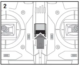
- Center all trims. The trims should always remain in the center position. If you feel the trims need to be adjusted please perform the trim flight procedure located towards the back of this manual.
- Attach the hook material to the helicopter frame and the loop material to the flight battery.
- Install the flight battery on the helicopter frame. Secure the flight battery with the hook and loop strap.
NOTICE: If the flight battery hook and loop strap is pulled too tight, it may result in a vibration or the tail rotor may drift during flight. If you experience either of these issues, loosen the strap slightly and fly again.
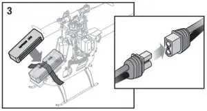
CAUTION: Connecting the battery to the ESC with reversed polarity will cause damage to the ESC, the battery or both. Damage caused by incorrectly connecting the battery is not covered under warranty.
If you experience issues during initialization, refer to the Troubleshooting Guide at the back of the manual.
CAUTION: Always disconnect the Li-Po battery from the aircraft when not flying to avoid over-discharging the battery. Batteries discharged to a voltage lower than the lowest approved voltage may become damaged, resulting in loss of performance and potential fire when batteries are charged.
WARNING: Always activate throttle hold and wait until the main rotor blades and tail rotor stop spinning before handling the model.
The throttle trim on the transmitter must remain at the center position. Raising the throttle trim above center may cause the main and tail motors to begin spinning.
LED Indicator on Flight Controller
| LED Indicator on FC | Indicator Description |
| Red Solid | AR6250MHX waiting for receiver connection, system will not initialize until connected |
| Yellow Flash | Calibrating |
| Slow Green Flash | Ready to Fly |
| Slow Red Flash | Failsafe Active |
| Red Solid and Yellow Flash | Calibration Error, FC not level or is being moved during calibration |
SMART Throttle
The new line of Spektrum ESCs feature a telemetry function called SMART Throttle. SMART Throttle technology combines the throttle signal with telemetry data from the ESC on one normal three wire servo connector.
SMART Throttle ESCs can send current, voltage, ESC temp, and mAh consumed. They can also pass along battery data from compatible Spektrum SMART batteries. SMART Throttle telemetry data shows up on your transmitter like any other telemetry sensor.
For SMART Throttle to function you must have a SMART Throttle ESC paired with a SMART Throttle telemetry receiver, and a Spektrum DSMX transmitter with telemetry. Only certain Spektrum products include SMART technology compatibility, check your receiver and ESC manual for more information. An update for your transmitter may be required for SMART features. (See www.spektrumrc.com to register and update your transmitter.)
To activate SMART Telemetry:
- Keep the vehicle powered on after binding the transmitter to the receiver
- On your Spektrum transmitter, Scroll to the Telemetry screen
- Scroll to Settings
- Select Auto Config
To activate Speed infomation using SMART Telemetry: - After doing the initial SMART telemetry configuration keep the vehicle powered on
- Scroll to the Telemetry screen
- Scroll to SMART ESC and double select
- Scroll down to NEXT
- Enter the values for the magnetic pole count of the motor and the gear ratio (motor and gear ratio information can be found in the manual for your vehicle)
When the radio is on and connected to a receiver sending SMART Data, the SMART Logo will appear under the battery logo on the home page and a signal bar will appear in the top left corner of the screen. Scrolling down, past the servo monitor, the SMART screens will appear. Select either ESC, battery, or both for display to suit your preference.
Low Voltage Cutoff (LVC)
The ESC will continuously lower power to the motor until complete shutdown when the battery reaches 9V under load. This helps prevent over-discharge of the Li-Po battery. Land immediately when the ESC activates LVC. Continuing to fly after LVC can damage the battery, cause a crash or both. Crash damage and batteries damaged due to over-discharge are not covered under warranty.
Repeatedly flying the helicopter until LVC activates will damage the helicopter battery.
Disconnect and remove the Li-Po battery from the aircraft after use to prevent trickle discharge. During storage, make sure the battery charge does not fall below 3V per cell.
Transmitter and Receiver Binding
This product requires an approved Spektrum DSM2®/DSMX® compatible transmitter. ® Visit www.bindnfly.com for a complete list of approved transmitters.
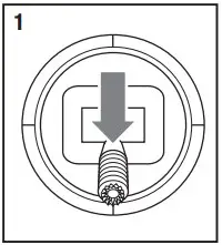
| General Binding Procedure |
| 1. Refer the Transmitter Setup Table to correctly setup your transmitter. |
| 2. Lower the throttle stick to the lowest position. Set all trims to the center position. |
| 3. Power off the transmitter and move all switches to the 0 position. Move the throttle to the low/off position. |
| 4. Install the bind plug in the receiver BIND/PROG port. |
| 5. Connect the flight battery to the ESC. |
| 6. Put the transmitter into bind mode while powering on the transmitter. Flip the model upside down and hold for |
| 15 seconds. |
| 7. Release the bind button/switch after 2–3 seconds. The helicopter is bound when the LED on the receiver turns solid. |
| 8. Disconnect the flight battery and power the transmitter off |
CAUTION: When using a Futaba® transmitter with a SpektrumTM DSM2® module, you must reverse the throttle channel and re-bind. Refer to your Spektrum module manual for binding and failsafe instructions. Refer to your Futaba transmitter manual for instructions on reversing the throttle channel.
SAFE Technology
Revolutionary SAFE® (Sensor Assisted Flight Envelope) technology uses an innovative combination of multi-axis sensors and software that allows model aircraft to know its position relative to the horizon. This spatial awareness is utilized to create a controlled flight envelope the aircraft can use to maintain a safe region of bank and pitch angles so you can fly more safely. Far beyond stability, this level of protection offers multiple modes so the pilot can choose to develop his or her skills with a greater degree of security and flight control that always feels crisp and responsive.
Flight Mode and Rate Selection
SAFE technology delivers:
- Flight envelope protection you can enable at the flip of
a switch. - Multiple modes let you adapt SAFE technology to your skill level instantly.
Best of all, sophisticated SAFE technology doesn’t require any work to enjoy. Every aircraft with SAFE installed is ready to use and optimized to offer the best possible flight experience.
FlySAFERC.com
Flight Mode and Rate Selection
In Stability Mode the bank angle is limited. When the cyclic stick is released the model will return to level. In Intermediate Mode the bank angle is not limited. When the cyclic stick is released the model will not return to level. This mode is great for learning forward flight and basic aerobatics such as stall turns and loops.
Panic Recovery
In Agility Mode the bank angle is not limited. When the cyclic stick is released the model will not return to level. This mode is great for 3D aerobatics such as stationary flips and tic tocs.
Change rates in any mode by moving the two-position dual rate switch.
- Low rate reduces the control rates, providing an easier to fly model. Beginners should use low rate for initial flights.
- High rate provides full control and should be used by intermediate and experience pilots.
Panic Recovery
If you get into distress while flying in any mode, activate the panic function and move the control sticks to their neutral position. SAFE technology will immediately return the aircraft to an upright level attitude, if the aircraft is at a sufficient height with no obstacles in its path. Return the collective stick to 50% and deactivate the Panic Recovery Function to return to the current flight mode.
NOTICE: Before deactivating Panic Recovery , make sure the collective stick has been returned to the 50% position. Once the Panic Recovery has been deactivated, full negative collective becomes available, which could cause the 150 S Smart to descend rapidly.
- This mode is intended to provide the pilot with the confidence to continue to improve their flight skills.
- Move the collective stick to 50% and return all other transmitter controls to neutral for the quickest recovery.
- Once the model has reached a level upright attitude, the negative collective is reduced to prevent the user from pushing the model into the ground.
Throttle Hold
Throttle hold is used to prevent the motor from powering on inadvertently. For safety, turn throttle hold ON any time you need to touch the helicopter or check the direction controls.
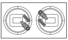
Control Tests
Throttle hold is also used to turn off the motor quickly if the helicopter is out of control, in danger of crashing, or both. The blades will continue to spin briefly when throttle hold is activated.
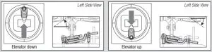
Control Tests
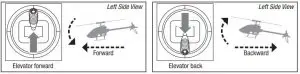
Ensure the throttle hold is ON when doing the direction control tests. Test the controls prior to the first flight to ensure the servos, linkages and parts operate correctly.
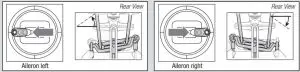
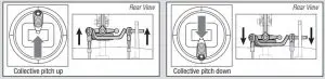
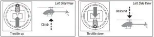
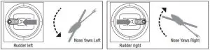
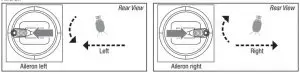
If the controls do not react as shown in the illustrations below, confirm the transmitter is programmed correctly before continuing on to the Motor test.
- Elevator
- Aileron
- Collective pitch
Motor
Place the helicopter outdoors on a clean, flat and level surface (concrete or asphalt) free of obstructions. Always stay clear of moving rotor blades.
CAUTION: Keep pets and other animals away from the helicopter. Animals may injure themselves if they attack or run toward the helicopter.
- Both motors beep 3 times when the helicopter’s ESC arms properly. Before you continue, confirm that throttle is at full low position.
- Turn Throttle Hold OFF.
WARNING: Stay at least 30 feet (10 meters) away from the helicopter when the motor is running. Do not attempt to fly the helicopter at this time. - Slowly increase the throttle until the blades begin to spin. The main blades should spin clockwise when viewing the helicopter from the top. The tail rotor blades should spin counterclockwise when viewing the helicopter from the right side.
NOTICE: If the main rotor blades are spinning counterclockwise, reduce the throttle to low immediately. Disconnect the battery from the helicopter and reverse any two motor wire connections to the ESC and repeat the motor control test.
Understanding the Primary Flight Controls
If you are not familiar with the controls of your aircraft, take a few minutes to familiarize yourself with them before attempting your first flight.
- Collective
- Rudder left Elevator
- Elevator
- Aileron
Flying the 150 S Smart
Consult your local laws and ordinances before choosing a location to fly your aircraft.
We recommend flying your aircraft outside in calm winds or inside a large gymnasium. Always avoid flying near houses, trees, wires and buildings. You should also be careful to avoid flying in areas where there are many people, such as busy parks, schoolyards or soccer fields.
It is best to fly from a smooth flat surface as this will allow the model to slide without tipping over. Keep the helicopter approximately 2 ft (600mm) above the ground. Keep the tail pointed toward you during initial flights to keep the control orientation consistent. Releasing the stick in Stability Mode will allow the helicopter to level itself. Activating the Panic Recovery button will level the helicopter quickly. If you become disoriented while in Stability Mode, slowly lower the throttle stick to land softly.
During initial flights, only attempt takeoff, landing and hovering in one spot.
Takeoff
NOTICE: If the main motor or tail motor do not start up properly when throttle is first applied, immediately return the throttle to the low position and try again. If the problem persists, disconnect the flight battery, check for binding in the gear train and ensure no wires have become entangled within the gears.
Place the model onto a flat, level surface free of obstacles and walk back 30 feet (10 meters). Slowly increase the throttle until the model is approximately 2 ft. (600mm) off the ground and begin flying the model.
Hovering
Making small corrections on the transmitter, try to hold the helicopter in one spot. If flying in calm winds, the model should require almost no corrective inputs. After moving the cyclic stick and returning it to center, the model should level itself. The model may continue to move due to inertia. Move the cycle stick in the opposite direction to stop the movement.
After you become comfortable hovering, you can progress into flying the model to different locations, keeping the tail pointed towards you at all times. You can also ascend and descend using the throttle stick. Once you’re comfortable with these maneuvers, you can attempt flying with the tail in different orientations. It is important to keep in mind that the flight control inputs will rotate with the helicopter, so always try to picture the control inputs relative to the nose of the helicopter. For example, forward will always drop the nose of the helicopter.
Low Voltage Cutoff (LVC)
LVC decreases the power to the motors when the battery voltage gets low. When the motor power decreases and the red LED on the ESC flashes, land the aircraft immediately and recharge the flight battery.
LVC does not prevent the battery from over-discharge during storage.
NOTICE: Repeated flying to LVC will damage the battery.
Landing
To land, slowly decrease the throttle while in a low-level hover. After landing, disconnect and remove the battery from the aircraft after use to prevent trickle discharge. Review your manufacturers provided LiPo guidelines for charging and storage information.
Advanced Tuning (Forward Programming)
Applies to forward programming capable Spektrum Transmitters including DX6e, DX8e, DX6G2, DX7G2, DX8G2, DX9, iX12, DX18, iX20, DX20, NX6, NX8, NX10 The 150 S Smart default settings are appropriate for most users. We recommend flying with the default parameters before making any adjustments.
The 150 S Smart BNF flight controller may be programmed from any compatible Spektrum transmitter (visit SpektrumRC.com for more information).
The flight controller shipped with BNF models has a range of adjustable parameters suitable for the 150 S Smart Helicopter and is not intended for use in other aircraft.
It is important to use the included servos with the BNF flight controller because the adjustable parameters available for the SPMAR6250MHXC are designed around the recommended servos. It is possible there may not be enough range for the helicopter to be tuned when using alternative servos.
Entering the Advanced Parameters Menu
With the helicopter bound to the transmitter and powered on, enter the Function List and select Forward Programming. The list of adjustable parameters and the range of values available for tuning have been tailored for this helicopter. Make small changes to one parameter at a time and test fly the changes before changing the parameter further or changing a different parameter.
Calibration Procedure:
If the helicopter is experiencing drift issues, perform the following calibration. The calibration procedure may also be needed following crash repairs.
- Ensure the surface used for calibration is level.
- Power on the transmitter and activate throttle hold.
- Connect the flight batter to the ESC and allowing the model to initialize.
- Turn Throttle Hold ON.
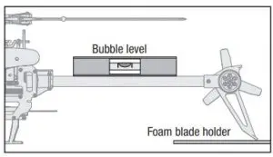
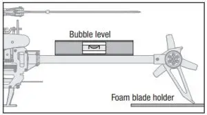
- Using a bubble level as shown below, level the helicopter by placing a shim under the landing skid.
- Enter the Function List on your transmitter.
- Select Forward Programming.
- Select System Setup.
- Select Calibration.
- Select Apply and the calibration will begin. The LED will flash yellow indicating the calibration is proceeding normally. If the LED changes to red this indicates the model is not near level or the model was moved, in this case the calibration starts over.
- After the calibration is successfully completed, the receiver LED will will change to a slow green flash which indicates the calibration has completed.
- Proceed to the pre-flight check list procedure before flying your model.
Factory Reset
If the process of tuning the 150 S Smart helicopter results in undesirable flight performance, you can reset the settings back to factory defaults by selecting the Factory Reset option in Forward Programming.
- Enter the Function List
- Select Forward Programming
- Select System Setup
- Select Factory Reset
- Select Apply
- Perform the Setup->Swashplate->Sub Trim function and ensure the servos are properly trimmed.
- Proceed with the pre-flight check list procedure before flying the model.
Advanced Tuning (Non-Forward Programming)
Applies to Spektrum transmitters not capable of forward programing including DX6i, DX6e, DX7s DX8, and DX8e
Your Blade 150 S Smart was setup at the factory and test flown. The servo adjustment steps are usually only necessary in special circumstances, such as after a crash or if a servo or linkage is replaced.
For pilots flying with a transmitter not capable of forward programming use the following procedures to make servo adjustments and perform the calibration procedure.
The advanced tuning options must be entered within 30 seconds after initialization completes. In addition the combination of dual rates and travel adjustments must result in a throw greater than 65% in order to enter the tuning modes.
Entering Servo Adjustment Mode
- Lower the throttle stick to the lowest position.
- Power ON the transmitter and activate throttle hold.
- Install the flight battery on the helicopter frame, securing it with the hook and loop strap.
- Connect the battery connector to the ESC.
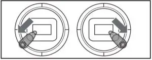
- After initialization is complete (indicated by a slowgreen flash), hold the left stick to the bottom left corner and the right stick to the bottom right corner as shown.
- Servo Adjustment Mode is indicated by the swashplate servos jumping and then slowly moving back to center.
- Release the sticks and proceed to the next step.
Adjusting the Servo Neutral Position
With the model in Servo Adjustment Mode, the control stick and gyro inputs are disabled and the servos are held in the neutral position. Check the position of the servo arms to verify they are perpendicular to the servos.
- If the arms are perpendicular to the servos, no adjustment is necessary. Exit Servo Adjustment Mode.
- If one or more servo arm is not perpendicular to the servos, continue the servo adjustment process.
While watching the swashplate servos, apply fore or aft cyclic and release. One of the servos will jump, indicating the selected servo. Apply fore or aft cyclic and release until the servo that needs to be adjusted is selected.
Once the servo you wish to adjust is selected, move the cyclic stick left or right to adjust the servo neutral position in the desired direction.
To reset the current servo to the default neutral position, hold the rudder stick full right for two seconds.
The range of adjustment is limited. If you are unable to adjust the servo arm to be perpendicular to the servo, you must reset the servo to the default neutral position, remove the servo arm and place it back onto the servo as close to perpendicular as possible. You may then adjust the servo neutral position using left or right cyclic stick.
Swashplate Leveling
Before saving your adjustments and exiting servo adjustment mode, verify the swashplate is level and both main rotor blades are at 0 degrees pitch.
If they are not, make linkage adjustments as necessary.
Saving the Servo Adjustments
- Lower the throttle stick to the lowest position and release the sticks.
- Move the tail rotor stick to the left and hold for four seconds to exit Servo Adjustment Mode. The servos will jump indicating a return to normal operation.
- Release the tail rotor stick.
- Perform the pre-flight checklist procedure before flying your model.
| Control Input in Servo Adjustment Mode | Action in Servo Adjustment Mode |
| Fore/Aft Cyclic | Select Previous or Next Servo |
| Right/Left Cyclic | Increase or Decrease Sub Trim Adjustment |
| Right Tailrotor | Hold For Two Seconds; Neutral Position is Reset on Selected Servo |
| Left Tailrotor and Low throttle | Hold for Four Seconds; Exit Servo Adjustment mode |
Servo Adjustment
Your helicopter was setup at the factory and test flown. The servo adjustment steps are only necessary in special circumstances, such as after a crash or if a servo or linkage is replaced.
WARNING: To ensure your safety, always disconnect the motor wires from the ESC before performing the following steps. After you have completed the adjustments, reconnect the motor wires to the ESC before attempting to fly the model.
Entering Servo Adjustment Mode
- Lower the throttle stick to the lowest position.
- Power ON the transmitter.
- Install the flight battery on the helicopter frame, secur- ing it with the hook and loop strap.
- Connect the battery connector to the ESC.
- Place the helicopter on a flat surface and leave it still
until the orange receiver LED glows solid, indicating initialization is complete. - Set the rate switch on the transmitter to the high rate.
- Hold the left stick to the bottom left corner and the right stick to the bottom right corner as shown.
- Activate the panic recovery function until the swash servos move.
- Release the sticks and deactivate panic recovery. The model is now in Gain Adjustment Mode.
- Proceed to Adjusting the Servo Neutral Position to make any desired changes.
Adjusting the Servo Neutral Position
With the model in Servo Adjustment Mode, the control stick and gyro inputs are disabled and the servos are held in the neutral position. Check the position of the servo arms to see if they are perpendicular to the servos.
- If the arms are perpendicular to the servos, no adjustment is necessary. Exit Servo Adjustment Mode.
- If one or more servo arm is not perpendicular to the servos, continue the servo adjustment process.
While watching the swashplate servos, apply right cyclic and release. One of the servos will jump, indicating which servo is selected. Press right cyclic and release until the servo that needs to be adjusted is selected.
Once the servo you wish to adjust is selected, move the cyclic stick forward or backward to adjust the servo neutral position in the desired direction.
If you would like to reset the current servo to the default neutral position, hold the rudder stick full right for 1 second.
The range of adjustment is limited. If you are unable to adjust the servo arm to be perpendicular to the servo, you must reset the servo to the default neutral position, remove the servo arm and place it back onto the servo as close to perpendicular as possible. You may then adjust the servo neutral position using the forward/backward cyclic stick.
Saving the Servo Adjustments
Before saving your adjustments and exiting servo adjustment mode, verify the swashplate is level and both main rotor blades are at 0 degrees. If they are not, make linkage adjustments as necessary.
- Lower the throttle stick to the lowest position and release the sticks.
- Press and hold switch I until the swash servos move.
- Release switch I to save the servo adjustments.
- Disconnect the flight battery from the ESC.
- Reconnect the main drive motor to the ESC. Your model is now ready for flight.
All of the settings are stored internally, so your adjustments will be maintained each time you initialize the model.
Trim Flight
Perform this procedure if the model is not performing well or has been recently rebuilt from a crash.
The trim flight procedure was performed during the factory test flight and only needs to be performed if you notice the model is not returning to level consistently or if the model does not remain still during stationary pirouettes.
The trim flight is used to determine the optimal settings for SAFE® technology during flight.
The trim flight must be performed in calm conditions.
Entering Trim Flight Mode
- Lower the throttle stick to the lowest position.
- Center all trims.
- Power ON the transmitter.
- Install the flight battery in the helicopter.
- Connect the battery connector to the ESC.
- Place the helicopter on a flat surface and leave it still
until the motor beeps twice and the blue ESC LED glows solid, indicating initialization is complete. - Place the helicopter where you are going to take off.
- Move and hold the left stick to the bottom left corner and the right stick to the top left corner as shown.
- Activate Panic Recovery until the swashplate rotates around once.
- Release the sticks and deactivate panic recovery.
- The model is ready for the trim flight.
Performing the Trim Flight
- Slowly increase the throttle to lift the model into a stationary hover. Make corrections as necessary to keep the model still. Evaluation does not begin until the throttle stick is over 50% and the sticks are centered. Making corrections will not affect the result but a longer flight may be necessary.
- Keep the model stationary in a hover for 120 seconds. Sliding and slow movements are okay. The main goal is to keep the rotor disk level.
- Once you are satisfied with the trim flight, land the model.
Exiting Trim Flight Mode
- After landing, lower the throttle stick to the lowest position.
- Activate Panic Recovery for 2 seconds, or until the swashplate moves, indicating the servo positions and attitude values have been recorded and trim flight mode has been exited.
Flight Test
After performing the trim flight, test-fly the model to evaluate the leveling characteristics.
- The model should return to level flight consistently. necessary. If you are still experiencing problems after several attempts please perform the calibration procedure and try the trim flight procedure again.
- During takeoff, the model should lift off with minimal corrections
- During a hover, the control stick should remain close to center. Small corrections are acceptable.
If the model performs poorly or does not level properly after the trim flight, retry the entire trim flight procedure. If the problem persists, inspect the model for damaged components, a bent shaft or anything that may result in increased vibration. The trim flight may not record the correct values due to excessive vibration, flying in wind or the model not staying level. In these cases, shorter trim flights may be necessary. If you are still experiencing problems after several attempts please perform the calibration procedure and try the trim flight procedure again.
Calibration Procedure
If the Blade 150 S Smart is experiencing drift issues after completing the trim flight procedure located at www.bladehelis. com, perform the following calibration. The calibration procedure may also be needed following crash repairs.
 WARNING: Before beginning the calibration procedure, disconnect the main motor and tail motor leads to prevent accidental motor startup during calibration.
To perform the calibration procedure:
- Ensure the surface used for calibration is level.
- Power on the transmitter and helicopter, allowing them to initialize.
- Turn Throttle Hold ON
- Ensure the main motor and tail motor leads are disconnected. Set the flight mode switch to Intermediate Mode (FM1).
- Using a bubble level as shown below, level the helicopter by placing the Blade 150 S Smart foam blade holder under the tail fin. Use additional items, as necessary, to build up under the tail fin until the tail boom is level.
- Hold the left stick to the bottom right corner, the right stick to the upper left corner and activate the Panic Recovery function until the LED on the receiver flashes once
- Release both sticks and deactivate the Panic Recovery function
- The LED on the receiver will remain solid for 1-2 minutes while the calibration takes place. Do not move the helicopter until the calibration is completed. If the LED begins blinking rapidly, an error has occurred. Begin the calibration procedure again, starting with step Bubble leve
- After the calibration is successfully completed, the receiver LED will blink slowly (2 seconds on, 2 seconds off).
- Power the helicopter off.
- Reconnect the main motor and tail motor wires Foam blade holder
- Perform the trim flight procedure
- During subsequent flights after the trim flight, the helicopter should return to within 5 degrees of level consistently.
Post-Flight Inspection and Maintenance Checklist
| Ball Links | Make sure the plastic ball link holds the control ball, but is not tight (binding) on the ball. When a link is too loose on the ball, it can separate from the ball during flight and cause a crash. Replace worn ball links before they fail. |
| Cleaning | Make sure the battery is not connected before cleaning. Remove dust and debris with a soft brush or a dry, lint-free cloth. |
| Bearings | Replace bearings when they become notchy (sticky in places when turning) or draggy |
| Wiring | Make sure the wiring does not contact moving parts. Replace damaged wiring and loose connectors. |
| Fasteners | Make sure there are no loose screws, other fasteners or connectors. Do not over-tighten metal screws in plastic parts. Tighten screws so the parts are mated together, then turn the screw only 1/8th of a turn more |
| Rotors | Make sure there is no damage to rotor blades and other parts which move at high speed. Damage to these parts includes cracks, burrs, chips or scratches. Replace damaged parts before flying. Verify both main rotor blades have the correct and equal tension in the blade grips. When the helicopter is held up sideways, the main blades should support their own weight. When the helicopter is shaken lightly, the blades should fall |
| Tail | Inspect the tail rotor for damage and replace if necessary. Verify the tail motor bolts, tail rotor adapter bolts and tail motor mount bolts are properly tightened. Inspect the tail boom for any damage and replace if necessary |
| Mechanics | Inspect the main frame and landing gear for damage and replace if necessary. Check the mainshaft for vertical play and adjust the locking collar if necessary. Verify that the main gear mesh is correct and that no tight spots exist in the 360 degree rotation. Inspect all wires for damage and replace as necessary. |
Troubleshooting Guide
| Problem | Possible Cause | Solution |
| Helicopter control response is inconsistent or requires extra trim to neutralize movement | Aircraft was not initialized properly or a vibration is interfering with the sensor operation | Disconnect the flight battery, center the control trim and re-initialize the helicopter |
| Helicopter will not respond to throttle | Throttle too high and/or throttle trim is too high | Disconnect the flight battery, place the throttle stick in the lowest position and move the throttle trim to the center position. Connect the flight battery and allow the model to initialize |
| Helicopter moved during initialization | ||
| Helicopter has reduced flight time or is underpowered | Flight battery charge is low | Completely recharge the flight battery |
| Flight battery is damaged | Replace the flight battery and follow the flight battery instructions | |
| Flight conditions might be too cold | Make sure the battery is warm (room temperature) before use | |
| LED on receiver flashes rapidly and aircraft will not respond to transmitter (during binding) | Bind switch or button was not held while transmitter was powered on | Power off transmitter and repeat bind process |
| Aircraft or transmitter is too close to large metal object, wireless source or another transmitter | Move aircraft and transmitter to another location and attempt binding again | |
| LED on the receiver flashes rapidly and the helicopter will not respond to the transmitter (after binding) | The bind plug was not removed from the receiver after binding | Disconnect the flight battery, remove the bind plug from the receiver and reconnect the flight battery |
| Less than a 5-second wait between first powering on the transmitter and connecting the flight battery to the helicopter | Leave the transmitter powered on. Disconnect and reconnect the flight battery to the helicopter | |
| The helicopter is bound to a different model memory (ModelMatch™ transmitters only) | Select the correct model memory on the transmitter. Disconnect and reconnect the flight battery to the helicopter | |
| Flight battery or transmitter battery charge is too low | Replace or recharge batteries | |
| Aircraft or transmitter is too close to large metal object, wireless source or another transmitter | Move aircraft and transmitter to another location and attempt connecting again | |
| Helicopter vibrates or shakes in flight | Damaged rotor blades, spindle or blade grips | Check main rotor blades and blade grips for cracks or chips. Replace damaged parts. Replace bent spindle |
| Random movements in flight | Vibration | Verify the receiver is properly attached to the helicopter. Inspect mounting tape for damage. Verify that no wires are contacting the receiver. Inspect and balance all rotating components. Verify the main shaft and tail rotor adapter are not damaged or bent. Inspect mechanics for broken or damaged parts and replace as necessary |
| Tail oscillation/wag or poor performance | Damaged tail rotor, main gear mesh, loose bolts, vibration | Verify that the boom support bolts are tight and the plastic boom support ends are properly adhered to the boom support rods. Inspect the tail rotor for damage. Verify that all bolts on the tail assembly are properly tightened. Verify main gear mesh and ensure no tight spots in the mesh through full rotation. Replace any damaged or worn components |
| Drift in calm winds | Vibration, damaged linkage, damaged servo | Under normal operation the transmitter trims should not require adjustment and the center positions are memorized during initialization. If you find that trim adjustments are necessary after take off, verify the balance of all rotating components, ensure the linkages are not damaged and make sure the servos are in proper working condition |
| Drift in calm winds | Vibration, damaged linkage, damaged servo | Under normal operation the transmitter trims should not require adjustment and the center positions are memorized during initialization. If you find that trim adjustments are necessary after take off, verify the balance of all rotating components, ensure the linkages are not damaged and make sure the servos are in proper working condition Drift in wind Normal The model will drift with the wind |
| Drift in wind | Normal | The model will drift with the wind but should remain level in flight. Simply hold the cyclic stick in the necessary position to keep the model stationary. The model must lean into the wind to remain stationary, if the model remains level then it will drift with the wind |
| Panic Recovery or Return to Level does not level the model | Model was not initialized on a level, still surface | Re-initialize the model on a level and still surface |
| Model was not taken off of a level surface | Always lift off from a level surface | |
| Severe vibration | Battery strapped too tightly to the model | Loosen the battery strap |
| Rotating component out of balance | Check the main shaft, tail rotor, main rotor blades, main frame and adapter for damage, replace as necessary. Vibration must be minimized for Panic Recovery and Return to Level functions to work properly |
Exploded View
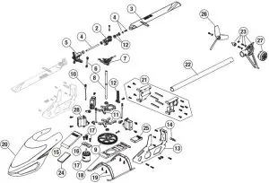
Parts List
| Part # | Description | |
| 1 | BLH1914 | Canopy Grommets (8) |
| 2 | BLH3401 | Main Blade Grips: 150 S, 180 CFX |
| 3 | BLH3402 | Main Blades: 150 S, 180 CFX |
| 4 | BLH3403 | Feathering Spindle Set: 150 S, 180 CFX |
| 5 | BLH3404 | 4 Main Rotor Head Block: 150 S, 180 CFX |
| 6 | BLH3405 | Rotor Head Linkage Set: 150 S, 180 CFX |
| 7 | BLH3406 | Swashplate: 150 S, 180 CFX |
| 8 | BLH3407 | Main Shaft Set: 150 S, 180 CFX |
| 9 | 9 BLH3408 | Main Gear: 150 S, 180 CFX |
| 10 | BLH3410 | Servo Control Link Set: 150 S, 180 CFX |
| 11 | BLH3411 | Main Bearing Block Set: 150 S, 180 CFX |
| 12 | BLH3412 | Anti-Rotation Bracket: 150 S, 180 CFX |
| 13 | BLH3413 | Carbon Fiber Main Frame: 180 CF |
| 14 | BLH3414 | Body Post Set: 150 S, 180 CFX |
| 15 | BLH3415 | Battery Tray: 150 S, 180 CFX |
| 16 | BLH3416 | Motor Mount: 150 S, 180 CFX |
| 17 | BLH3417 | Brushless Main Motor: 150 S, 180 CFX |
| 18 | BLH3418 | Bottom Plate: 150 S, 180 CFX |
| 19 | BLH3419 | Landing Gear: 150 S, 180 CFX |
| 20 | BLH5401 | Stock Canopy: 150 S |
| 21 | BLH5402 | Tailboom Mount: 150 S |
| 22 | BLH5403 | Tailboom (2): 150 S |
| 23 | BLH5404 | Tail Fin Mount (White): 150 S |
| 24 | SPMXAE2020 | ESC: 150 S |
| 25 | SPMAR6250MHXC | Replacement Receiver: 150 S |
| 26 | BLH9307 | Tail Rotor Blade Set: 150 S, 130 S |
| 27 | BLH9311 | Brushless Tail Motor: 150 S, 130 S |
| 28 | SPMSH2065 | Nanolite High Speed MG Heli SX |
Recommended Parts List
| Part # | Description |
| SPMX4503S50 | 450mAh 3S 50C w/IC-2 |
| SPMR12000 | iX12 12 Channel Transmitter Only |
| SPMR6750 | DX6 Transmitter Only MD2 G3 |
| SPMR8000 | DX8 Transmitter Only MD2 |
| SPMR9910 | DX9 Black Transmitter Only MD2 |
| SPMXC1000 | “Smart S1200 DC Charger, 1x200W” |
| SPMXC1010 | Smart S2100 AC Charger, 2X100W” |
| SPMR6775 | NX6 6-Channel Transmitter Only |
| SPMR8200 | NX8 8-Channel Transmitter Only |
| SPMXBC100 | XBC100 Smart LiPo Battery Checker & Servo Driver |
| SPMXCA320 | Adapter, 6″: IC3 Battery/IC2 Device |
Optional Parts List
| Part # | Description |
| BLH3409 | Stock Canopy: 180 CFX |
| BLH3409A | A Option Canopy: 180 CFX |
| BLH3409B | Fiberglass Canopy: 180 CFX |
| BLH9305 | Tail Fin/Motor Mount Set: 130 S |
| SPMA3065 | AS3X Programming Cable – USB Interface |
Limited Warranty
What this Warranty Covers
Horizon Hobby, LLC, (Horizon) warrants to the original purchaser that the product purchased (the “Product”) will be free from defects in materials and workmanship at the date of purchase.
What is Not Covered
This warranty is not transferable and does not cover
- cosmetic damage
- damage due to acts of God, accident, misuse, abuse, negligence, commercial use, or due to improper use, installation, operation or maintenance
- modification of or to any part of the Product
- attempted service by anyone other than a Horizon Hobby authorized service center
- Product not purchased from an authorized Horizon dealer
- Product not compliant with applicable technical regulations, or
- use that violates any applicable laws, rules, or regulations.
OTHER THAN THE EXPRESS WARRANTY ABOVE, HORIZON MAKES NO OTHER WARRANTY OR REPRESENTATION, AND HEREBY DISCLAIMS ANY AND ALL IMPLIED WARRANTIES, INCLUDING, WITHOUT LIMITATION, THE IMPLIED WARRANTIES OF NON-INFRINGEMENT, MERCHANTABILITY AND FITNESS FOR A PARTICULAR PURPOSE. THE PURCHASER ACKNOWLEDGES THAT THEY ALONE HAVE DETERMINED THAT THE PRODUCT WILL SUITABLY MEET THE REQUIREMENTS OF THE PURCHASER’S INTENDED USE.
Purchaser’s Remedy
Horizon’s sole obligation and purchaser’s sole and exclusive remedy shall be that Horizon will, at its option, either
- Service, or
- Replace, any Product determined by Horizon to be defective. Horizon reserves the right to inspect any and all Product(s) involved in a warranty claim. Service or replacement decisions are at the sole discretion of Horizon. Proof of purchase is required for all warranty claims. SERVICE OR REPLACEMENT AS PROVIDED UNDER THIS WARRANTY IS THE PURCHASER’S SOLE AND EXCLUSIVE REMEDY.
Limitation of Liability
HORIZON SHALL NOT BE LIABLE FOR SPECIAL, INDIRECT, INCIDENTAL OR CONSEQUENTIAL DAMAGES, LOSS OF PROFITS OR PRODUCTION OR COMMERCIAL LOSS IN ANY WAY, REGARDLESS OF WHETHER SUCH CLAIM IS BASED IN CONTRACT, WARRANTY, TORT, NEGLIGENCE, STRICT LIABILITY OR ANY OTHER THEORY OF LIABILITY, EVEN IF HORIZON HAS BEEN ADVISED OF THE POSSIBILITY OF SUCH DAMAGES. Further, in no event shall the liability of Horizon exceed the individual price of the Product on which liability is asserted. As Horizon has no control over use, setup, final assembly, modification or misuse, no liability shall be assumed nor accepted for any resulting damage or injury. By the act of use, setup or assembly, the user accepts all resulting liability. If you as the purchaser or user are not prepared to accept the liability associated with the use of the Product, purchaser is advised to return the Product immediately in new and unused condition to the place of purchase.
Law
These terms are governed by Illinois law (without regard to conflict of law principals). This warranty gives you specific legal rights, and you may also have other rights which vary from state to state. Horizon reserves the right to change or modify this warranty at any time without notice
WARRANTY SERVICES
Questions, Assistance, and Services
Your local hobby store and/or place of purchase cannot provide warranty support or service. Once assembly, setup or use of the Product has been started, you must contact your local distributor or Horizon directly. This will enable Horizon to better answer your questions and service you in the event that you may need any assistance. For questions or assistance, please visit our website at www.horizonhobby.com, submit a Product Support Inquiry, or call the toll free telephone number referenced in the Warranty and Service Contact Information section to speak with a Product Support representative.
Inspection or Services
If this Product needs to be inspected or serviced and is compliant in the country you live and use the Product in, please use the Horizon Online Service Request submission process found on our website or call Horizon to obtain a Return Merchandise Authorization (RMA) number. Pack the Product securely using a shipping carton. Please note that original boxes may be included, but are not designed to withstand the rigors of shipping without additional protection. Ship via a carrier that provides tracking and insurance for lost or damaged parcels, as Horizon is not responsible for merchandise until it arrives and is accepted at our facility. An Online Service Request is available at http://www.horizonhobby.com/content/_service-center_render-service-center. If you do not have internet access, please contact Horizon Product Support to obtain a RMA number along with instructions for submitting your product for service. When calling Horizon, you will be asked to provide your complete name, street address, email address and phone number where you can be reached during business hours. When sending product into Horizon, please include your RMA number, a list of the included items, and a brief summary of the problem. A copy of your original sales receipt must be included for warranty consideration. Be sure your name, address, and RMA number are clearly written on the outside of the shipping carton.
NOTICE:
Do not ship Li-Po batteries to Horizon. If you have any issue with a Li-Po battery, please contact the appropriate Horizon Product Support office.
Warranty Requirements
For Warranty consideration, you must include your original sales receipt verifying the proof-of-purchase date. Provided warranty conditions have been met, your Product will be serviced or replaced free of charge. Service or replacement decisions are at the sole discretion of Horizon.
Non-Warranty Service
Should your service not be covered by warranty, service will be completed and payment will be required without notification or estimate of the expense unless the expense exceeds 50% of the retail purchase cost
By submitting the item for service you are agreeing to payment of the service without notification. Service estimates are available upon request. You must include this request with your item submitted for service. Non-warranty service estimates will be billed a minimum of ½ hour of labor. In addition you will be billed for return freight. Horizon accepts money orders and cashier’s checks, as well as Visa, MasterCard, American Express, and Discover cards. By submitting any item to Horizon for service, you are agreeing to Horizon’s
Terms and Conditions found on our website http://www. horizonhobby.com/content/_service-center_render-servicecenter.
ATTENTION:
Horizon service is limited to Product compliant in the country of use and ownership. If received, a non-compliant Product will not be serviced Further, the sender will be responsible for arranging return shipment of the un-serviced Product, through a carrier of the sender’s choice and at the sender’s expense. Horizon will hold non-compliant Product for a period of 60 days from notification, after which it will be discarded 10/15
Warranty and Service Contact Information
| Country of Purchase | Horizon Hobby | Contact Information | Address |
| United States of America | Horizon Service Center (Repairs and Repair Requests | servicecenter.horizonhobby.com/RequestForm/ | 2904 Research Rd Champaign, Illinois, 61822 USA |
| Horizon Product Support (Product Technical Assistance) | [email protected]
877-504-0233 |
2904 Research Rd Champaign, Illinois, 61822 USA | |
| Sales | [email protected] | ||
| 800-338-4639 | |||
| European Union | Horizon Technischer Service | [email protected] | Hanskampring 9
D22885 Barsbüttel, Germany |
| Sales: Horizon Hobby GmbH | +49 (0) 4121 2655 100 |
FCC Information
Contains FCC ID: BRWWACO1T
This equipment complies with FCC and IC radiation exposure limits set forth for an uncontrolled environment. This equipment should be installed and operated with minimum distance 20cm between the radiator and/or antenna and your body (excluding fingers, hands, wrists, ankles and feet). This transmitter must not be co-located or operating in conjunction with any other antenna or transmitter.
Supplier’s Declaration of Conformity
BLADE® 150 S Smart BNF BASIC (BLH54500)
 This device complies with part 15 of the FCC Rules. Operation is subject to the following two conditions: (1) This device may not cause harmful
interference, and (2) this device must accept any interference received, including interference that may cause undesired operation.
 CAUTION:
Changes or modifications not expressly approved by the party responsible for compliance could void the user’s authority to operate the equipment.
NOTE:
This equipment has been tested and found to comply with the limits for a Class B digital device, pursuant to part 15 of the FCC Rules. These limits are designed to provide reasonable protection against harmful interference in a residential installation. This equipment generates, uses and can radiate radio frequency energy and, if not installed and used in accordance with the instructions, may cause harmful interference to radio communications. However, there is no guarantee that interference will not occur in a particular installation. If this equipment does cause harmful interference to radio or television reception, which can be determined by turning the equipment off and on, the user is encouraged to try to correct the interference by one or more of the following measures
- Reorient or relocate the receiving antenna
- Increase the separation between the equipment and receiver.
- Connect the equipment into an outlet on a circuit different from that to which the receiver is connected
- Consult the dealer or an experienced radio/TV technician for help.
Horizon Hobby, LLC 2904 Research Rd., Champaign, IL 61822 Email: [email protected] Web: HorizonHobby.com
IC Information
CAN ICES-3 (B)/NMB-3(B)
Contains IC: 6157A-WACO1T
This device contains license-exempt transmitter(s)/receivers(s) that comply with Innovation, Science, and Economic Development Canada’s license-exempt RSS(s). Operation is subject to the following 2 conditions
- This device may not cause interference.
- This device must accept any interference, including interference that may cause undesired operation of
the device.
Compliance Information for the European Union
EU Compliance Statement:
 BLADE 150 S Smart BNF BASIC (BLH54500) Hereby, Horizon Hobby, LLC declares that the device is in compliance with the following: EU Radio Equipment Directive 2014/53/EU, RoHS 2 Directive 2011/65/EU, RoHS 3 Directive – Amending 2011/65/EU Annex II 2015/863
NOTE:
This product contains batteries that are covered under the 2006/66/EC European Directive, which cannot be disposed of with normal household waste. Please follow local regulations.
The full text of the EU declaration of conformity is available at the following internet address:
https:// www.horizonhobby.com/content/support-rendercompliance.
Wireless Frequency Range and Wireless Output Power:
WEEE NOTICE:

 This appliance is labeled in accordance with European Directive 2012/19/EU concerning waste of electrical and electronic equipment (WEEE). This label indicates that this product should not be disposed of with household waste. It should be deposited at an appropriate facility to enable recovery and recycling.
EU Manufacturer of Record
Horizon Hobby, LLC 2904 Research Road Champaign, IL 61822 USA
EU Importer of Record
Horizon Hobby, GmbH Hanskampring 9 22885 Barsbüttel Germany
Australia/New Zealand: