INTEX CS3110 Salt Water System
IMPORTANT SAFETY RULES
Read, Understand and Follow All Instructions Carefully Before Installing and Using this Product.
READ AND FOLLOW ALL INSTRUCTIONS
WARNING
- For Outdoor use only.
- Not to energize or operate the unit if the cell housing is damaged or improperly assembled.
- To reduce the risk of injury, do not permit children to use this product. Always supervise children and those with disabilities.
- Children must stay away from this product and all electrical cords.
- Assembly and disassembly by adults only.
- Risk of electric shock. Connect only to a grounding-type receptacle, this product is provided with a ground-fault circuit interrupter. If replacement of the plug or cord is needed, use only identical replacement parts.
- Always unplug this product from the electrical outlet before removing, cleaning, servicing or making any adjustment to the product.
- The unit is provided with a ground-fault circuit interrupter (GFCI). To test the GFCI, push the test button. The GFCI should interrupt power. Push the reset button, power should be restored. If the GFCI fails to operate in this manner. The GFCI is defective. If the GFCI interrupts power to the pump without the test button being pushed, a ground current is flowing, indicating the possibility of an electric shock. Do not use this pump. Disconnect the pump and have the problem corrected by a qualified service representative before using.
- Do not bury the electrical cord. Locate the cord where it will not be damaged by lawn mowers, hedge trimmers and other equipment.
- To reduce the risk of electric shock, the supply cord cannot be replaced. If the cord is damaged, the appliance should be replaced immediately.
- To reduce the risk of electric shock, do not use extension cords, timers, plug adaptors or converter plugs to connect unit to electric supply; provide a properly located outlet.
- Do not attempt to plug in or unplug this product while standing in water or when your hands are wet.
- Do not use an appliance leakage current interrupter (ALCI) in place of a GFCI since the ALCI will not protect people.
- Position this product away from the pool, so as to prevent children from climbing on it and accessing the pool.
- Make sure the electrical parameters indicated on the product correspond to the local mains voltage before you connect the unit.
- This product is intended to be used only for the purposes described in the manual!
FAILURE TO FOLLOW THESE WARNINGS MAY RESULT IN PROPERTY DAMAGE, ELECTRIC SHOCK, ENTANGLEMENT, OR OTHER SERIOUS INJURY OR DEATH.
This product is for use with storable pools only. Do not use with permanently-installed pools. A storable pool is constructed so that it is capable of being readily disassembled for storage and reassembled to its original integrity. A permanently-installed pool is constructed in or on the ground or in a building such that it cannot be readily disassembled for storage. To reduce the risk of electric shock the pool must be installed no closer than 6 feet (1.8 m) from any electrical outlet. Do not place portable appliances closer than 5 feet (1.5 m) from the pool. These product warnings, instructions, and safety rules provided with the product represent some common risks of water recreation devices and do not cover all instances of risk and danger. Please use common sense and good judgment when enjoying any water activity For portable Above-Ground-Pools only
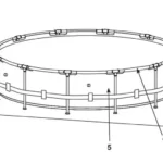
PARTS REFERENCE
NOTE: Drawings for illustration purposes only. The actual product may vary. Not to scale.
| REF. NO. | DESCRIPtION | Qty. | SPARE PARt NO. |
| 1 | CONTROL STATION | 1 | 12943 |
| 2 | CONNECTOR HOSE | 1 | 11873 |
| 3 | HOSE CLAMP | 2 | 11489 |
| 4 | CELL HOUSING O-RING | 2 | 12947 |
| 5 | CELL HOUSING | 1 | 12945 |
| 6 | TITANIUM ELECTRODE O-RING | 1 | 11585 |
| 7 | TITANIUM ELECTRODE | 1 | 12946 |
| 8 | ELECTROLYTIC CELL NUT | 1 | 11582 |
| 9 | TEST STRIPS | 1 | 19635 |
When ordering parts, be sure to quote the model number and part numbers.
PRODUCT SPECIFICATIONS
| Model: | CS3110 |
| Power: | 110 – 120 Volt AC |
| Amperage: | 0.5 A |
| Wattage: | 30 W |
| Ideal Salt Level: | 3000 ppm (parts per million) |
| Maximum sodium hypochlorite output/hour: | 4 grams/hour |
| Filter pump minimum and maximum flow rate: | 300 gallons/hour (1136 liters/hour) /
1000 gallons/hour (3785 liters/hour) |
| Limited Warranty: | see “Limited Warranty” |
| For pools and filter pumps with 1-¼” (32mm) hose connection fittings. | |
Please visit www.intexdevelopment.com/support/videos for the latest instructional video on the installation and operation of this product.
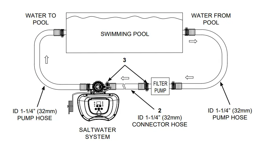
SETUP INSTRUCTIONS
IMPORTANT
- The Saltwater System requires a separate filter pump [300~1000 gph (1136~ 3785 lph)] to drive the water and function properly.
- The Saltwater System must be installed as the last piece of pool equipment in the water return line to the pool as displayed below. This location extends the life of the titanium plates.
- Remove any large debris and particles such as leaves, sand, insects, and bugs from the pool water first.
- Assemble the above-ground pool (AGP) and its filter pump according to their installation instructions.
- Take the Saltwater System and its accessories out of the packaging.
- Place the Saltwater System in line with the filter pump.
- Connect the connector hose (2) to the Saltwater System inlet with a hose clamp (3).
- Go directly to step 6 if your pool is empty. If your above-ground pool is filled with water, unscrew the strainer grids from the strainer connectors and insert the black hat-like plugs into the connectors, before installing the saltwater pool system.
- Disconnect the water return hose from the filter pump connection and connect it to the Saltwater System outlet.
- Connect the connector hose (2) to the filter pump outlet connection with a hose clamp (3). Tighten securely.
- Remove the black hat-like plugs that prevent water from flowing out of the pool. Now, return the strainer grids to the strainer connectors.
SALT and POOL WATER VOLUMES
Which kind of salt to use:
Use only Sodium Chloride Salts
Use only sodium chloride (NaCl) salt that is at least 99.8% pure. It is also acceptable to use water conditioning salt pellets (the compressed forms of evaporated salt). However, it will take a longer time for them to dissolve.
Do not use iodized or yellow (yellow prussiate of soda) colored salt. Salt is added to the pool water and the electrolytic cell uses the salt to create sodium hypochlorite. The purer the salt the better the performance of the electrolytic cell.
Optimum Salt Levels
The ideal salt level in the pool water is between 2500-3500 ppm (parts per million). The optimal level is 3000 ppm. A too low salt level will reduce the efficiency of the Saltwater System and result in low sodium hypochlorite production. A high salt level may generate a salty taste to the pool water (this may occur at a salt level above 3500-4000ppm). Too high a salt level may damage the power supply and cause corrosion to the pool metal fixtures and accessories. The Salt Table page of this manual shows the correct dosage of salt needed. The salt in the pool is constantly recycled.
Adding Salt
- Switch the filter pump on to start the water circulation.
- Keep the Saltwater System turned off.
- Determine the amount of salt to be added (see “Salt Table”).
- Evenly spread the proper amount of salt around the inside perimeter of the pool.
- Avoid clogging the filter. Do not add salt through the skimmer.
Brush the pool bottom to speed up the dissolving process. Do not allow the salt to pile up on the bottom of the pool. Run the filter pump for 24 consecutive hours to thoroughly dissolve the salt. After 24 hours and if all the salt is dissolved, turn on the Saltwater System, press the button, code “00” flashing and set the saltwater pool system to desired operating time (see “Operating Time Table”).
Removing Salt
If too much salt has been added, the unit will beep and display “Code 92” (see “Alarm Codes”). You will need to lower the salt concentration. The only way to do so, is to partially drain the pool and refill it with fresh water. Drain and refill approximately 20% of the pool’s water until the “Code 92” disappears.
Pool Volume Calculation
| types of Pool | Gallons
(pool size in feet) |
Cubic Meters
(pool size in meters) |
| Rectangular | Length x Width x Average Depth x 7.5 | Length x Width x Average Depth |
| Circular | Length x Width x Average Depth x 5.9 | Length x Width x Average Depth x 0.79 |
| Oval | Length x Width x Average Depth x 6.0 | Length x Width x Average Depth x 0.80 |
INTEX POOLS SALT TABLE
|
Pool Size |
Water Capacity (Calculated at 90% for Frame Pool and 80% for Easy Set & Oval Pool) | Salt Needed for Startup
3.0g/L (3000ppm) |
Salt Needed when Low Salt Detected (CODE “91”) | ||||
| (Gals) | (Liters) | (Lbs) | (Kgs) | (Lbs) | (Kgs) | ||
| INtEX AbOVE GROuND POOLS (AGP’s) | |||||||
|
EASy SEt® POOL |
244cmx61cm (8’x24”) | 513 | 1942 | 13 | 6 | 5 | 2 |
| 244cmx76cm (8’x30″) | 639 | 2419 | 16 | 7 | 5 | 2 | |
| 305cmx61cm (10’x24”) | 813 | 3077 | 20 | 9 | 7 | 3 | |
| 305cmx76cm (10’x30″) | 1018 | 3853 | 25 | 12 | 9 | 4 | |
| 366cmx76cm (12’x30″) | 1485 | 5621 | 37 | 17 | 13 | 6 | |
| 396cmx84cm (13’x33″) | 1926 | 7290 | 48 | 22 | 17 | 8 | |
| 457cmx84cm (15’x33″) | 2587 | 9792 | 65 | 29 | 21 | 10 | |
| 457cmx107cm (15’x42″) | 3284 | 12430 | 82 | 37 | 27 | 12 | |
| 457cmx122cm (15’x48″) | 3736 | 14141 | 94 | 42 | 31 | 14 | |
|
MEtAL FRAME POOL |
244cmx51cm (8’x20”) | 483 | 1828 | 13 | 6 | 5 | 2 |
| 305cmx76cm (10’x30″) | 1185 | 4485 | 30 | 13 | 9 | 4 | |
| 366cmx76cm (12’x30″) | 1718 | 6503 | 43 | 20 | 15 | 7 | |
| 457cmx122cm (15’x48″) | 4440 | 16805 | 111 | 50 | 37 | 17 | |
|
PRISM FRAMEtM POOL |
305cmx76cm (10’x30″) | 1185 | 4485 | 30 | 13 | 10 | 5 |
| 366cmx76cm (12’x30″) | 1718 | 6503 | 43 | 20 | 15 | 7 | |
| 366cmx99cm (12’x39″) | 2270 | 8592 | 57 | 26 | 19 | 9 | |
| 427cmx107cm (14’x42″) | 3357 | 12706 | 84 | 38 | 28 | 13 | |
| 457cmx107cm (15’x42″) | 3861 | 14614 | 97 | 44 | 32 | 15 | |
| 457cmx122cm (15’x48″) | 4440 | 16805 | 111 | 50 | 37 | 17 | |
|
PRISM FRAMEtM RECt. POOL |
300cmx175cmx80cm (9’10″x5’9″x31½”) | 935 | 3539 | 23 | 11 | 7 | 3 |
| 400cmx200cmx100cm (13’1½”x6’6¾”x39½”) | 1806 | 6836 | 45 | 21 | 15 | 7 | |
| 400cmx200cmx122cm (13’1½”x6’6¾”x48”) | 2224 | 8418 | 56 | 25 | 17 | 8 | |
| 488cmx244cmx107cm (16’x8’x42″) | 2873 | 10874 | 72 | 33 | 24 | 11 | |
|
SMALL RECt. FRAME POOL |
220cmx150cmx60cm
(7’2⅝”x4’11″x23⅝”) |
439 | 1662 | 11 | 5 | 3 | 1 |
| 260cmx160cmx65cm
(8’6½”x5’3″x25⅝”) |
603 | 2282 | 16 | 7 | 5 | 2 | |
| 300cmx200cmx75cm (9’10″x6’6¾”x29½”) | 1013 | 3834 | 25 | 12 | 9 | 4 | |
| 450cmx220cmx84cm
(14’9¼”x7’2⅝”x33″) |
1883 | 7127 | 48 | 22 | 17 | 8 | |
This table shows the amount of salt needed to achieve and maintain the optimal 3000 ppm salt level.
INTEX POOLS CYANURIC ACID TABLE
Cyanuric acid is a chemical that reduces the loss of chlorine in water due to ultraviolet rays. To maintain the pool water clear and clean, and to maximize the performance of the device, add cyanuric acid to the pool. We recommend that the cyanuric acid level be maintained at approximately 0.35% of the salt, i.e. 100 Lbs (45 Kgs) salt x0.35% = 0.35 Lbs (0.16 Kgs) cyanuric acid. If the pool water is dirty, filthy or grimy, DO NOT add chlorine stabilizer (cyanuric acid) as this will slowdown the sanitation time of the device. Under this condition you must BOOST your pool water, refer to BOOST cycle steps. Once the pool water has been restored to clear and clean conditions you may add cyanuric acid.
|
Pool Size |
Water Capacity (Calculated at 90% for Frame Pool and 80% for Easy Set & Oval Pool) | Cyanuric Acid Needed for Startup
0.01g/L (10ppm) |
|||
| (Gals) | (Liters) | (oz) | (g) | ||
| INtEX AbOVE GROuND POOLS (AGP’s) | |||||
|
EASy SEt® POOL |
244cmx61cm (8’x24”) | 513 | 1942 | 0.7 | 19 |
| 244cmx76cm (8’x30″) | 639 | 2419 | 0.9 | 25 | |
| 305cmx61cm (10’x24”) | 813 | 3077 | 1.1 | 31 | |
| 305cmx76cm (10’x30″) | 1018 | 3853 | 1.4 | 39 | |
| 366cmx76cm (12’x30″) | 1485 | 5621 | 2.0 | 56 | |
| 396cmx84cm (13’x33″) | 1926 | 7290 | 2.6 | 73 | |
| 457cmx84cm (15’x33″) | 2587 | 9792 | 3.5 | 98 | |
| 457cmx107cm (15’x42″) | 3284 | 12430 | 4.4 | 124 | |
| 457cmx122cm (15’x48″) | 3736 | 14141 | 5.0 | 141 | |
|
MEtAL FRAME POOL |
244cmx51cm (8’x20”) | 483 | 1828 | 0.7 | 19.0 |
| 305cmx76cm (10’x30″) | 1185 | 4485 | 1.6 | 45 | |
| 366cmx76cm (12’x30″) | 1718 | 6503 | 2.3 | 65 | |
| 457cmx122cm (15’x48″) | 4440 | 16805 | 5.9 | 168 | |
|
PRISM FRAMEtM POOL |
305cmx76cm (10’x30″) | 1185 | 4485 | 1.6 | 45 |
| 366cmx76cm (12’x30″) | 1718 | 6503 | 2.3 | 65 | |
| 366cmx99cm (12’x39″) | 2270 | 8592 | 3.0 | 86 | |
| 427cmx107cm (14’x42″) | 3357 | 12706 | 4.5 | 127 | |
| 457cmx107cm (15’x42″) | 3861 | 14614 | 5.2 | 146 | |
| 457cmx122cm (15’x48″) | 4440 | 16805 | 5.9 | 168 | |
|
PRISM FRAMEtM RECt. POOL |
300cmx175cmx80cm (9’10″x5’9″x31½”) | 935 | 3539 | 1.3 | 35 |
| 400cmx200cmx100cm (13’1½”x6’6¾”x39½”) | 1806 | 6836 | 2.4 | 68 | |
| 400cmx200cmx122cm (13’1½”x6’6¾”x48”) | 2224 | 8418 | 2.9 | 84 | |
| 488cmx244cmx107cm (16’x8’x42″) | 2873 | 10874 | 3.8 | 109 | |
|
SMALL RECt. FRAME POOL |
220cmx150cmx60cm
(7’2⅝”x4’11″x23⅝”) |
439 | 1662 | 0.6 | 17 |
| 260cmx160cmx65cm
(8’6½”x5’3″x25⅝”) |
603 | 2282 | 0.8 | 23 | |
| 300cmx200cmx75cm (9’10″x6’6¾”x29½”) | 1013 | 3834 | 1.4 | 39 | |
| 450cmx220cmx84cm
(14’9¼”x7’2⅝”x33″) |
1883 | 7127 | 2.5 | 71 | |
INTEX POOLS OPERATING TIMETABLE (WITH CYANURIC ACID)
| Pool Size | Water Capacity (Calculated at 90% for Frame Pool and 80% for Easy Set & Oval Pool) | Operating time (hours) at different ambient/air temperatures | Intex Filter pump Operating time (hours) | ||||
| (Gals) | (Liters) | 10 – 19°C
(50 – 66°F) |
20 – 28°C
(68 – 82°F) |
29 – 36°C
(84 – 97°F) |
|||
| Intex AbOVE GROuND POOLS (agps) | |||||||
| EASy SEt® POOL | 244cmx61cm (8’x24”) | 513 | 1942 | 1 | 1 | 1 | 2 |
| 244cmx76cm (8’x30″) | 639 | 2419 | 1 | 1 | 1 | 2 | |
| 305cmx61cm (10’x24”) | 813 | 3077 | 1 | 2 | 2 | 3 | |
| 305cmx76cm (10’x30″) | 1018 | 3853 | 2 | 2 | 2 | 3 | |
| 366cmx76cm (12’x30″) | 1485 | 5621 | 3 | 3 | 3 | 4 | |
| 396cmx84cm (13’x33″) | 1926 | 7290 | 3 | 4 | 4 | 5 | |
| 457cmx84cm (15’x33″) | 2587 | 9792 | 5 | 5 | 5 | 6 | |
| 457cmx107cm (15’x42″) | 3284 | 12430 | 6 | 6 | 7 | 8 | |
| 457cmx122cm (15’x48″) | 3736 | 14141 | 7 | 7 | 7 | 8 | |
| MEtAL FRAME POOL | 244cmx51cm (8’x20”) | 483 | 1828 | 1 | 1 | 1 | 2 |
| 305cmx76cm (10’x30″) | 1185 | 4485 | 2 | 2 | 2 | 3 | |
| 366cmx76cm (12’x30″) | 1718 | 6503 | 3 | 3 | 4 | 5 | |
| 457cmx122cm (15’x48″) | 4440 | 16805 | 8 | 8 | 8 | 9 | |
| PRISM FRAMEtM POOL | 305cmx76cm (10’x30″) | 1185 | 4485 | 2 | 2 | 2 | 3 |
| 366cmx76cm (12’x30″) | 1718 | 6503 | 3 | 3 | 4 | 5 | |
| 366cmx99cm (12’x39″) | 2270 | 8592 | 4 | 4 | 5 | 6 | |
| 427cmx107cm (14’x42″) | 3357 | 12706 | 6 | 6 | 7 | 8 | |
| 457cmx107cm (15’x42″) | 3861 | 14614 | 7 | 7 | 8 | 9 | |
| 457cmx122cm (15’x48″) | 4440 | 16805 | 8 | 8 | 8 | 9 | |
| PRISM FRAMEtM RECt. POOL | 300cmx175cmx80cm (9’10″x5’9″x31½”) | 935 | 3539 | 1 | 2 | 2 | 3 |
| 400cmx200cmx100cm (13’1½”x6’6¾”x39½”) | 1806 | 6836 | 3 | 3 | 4 | 5 | |
| 400cmx200cmx122cm (13’1½”x6’6¾”x48”) | 2224 | 8418 | 4 | 4 | 5 | 6 | |
| 488cmx244cmx107cm (16’x8’x42″) | 2873 | 10874 | 5 | 5 | 6 | 7 | |
| SMALL RECt. FRAME POOL | 220cmx150cmx60cm
(7’2⅝”x4’11″x23⅝”) |
439 | 1662 | 1 | 1 | 1 | 2 |
| 260cmx160cmx65cm
(8’6½”x5’3″x25⅝”) |
603 | 2282 | 1 | 1 | 1 | 2 | |
| 300cmx200cmx75cm (9’10″x6’6¾”x29½”) | 1013 | 3834 | 2 | 2 | 2 | 3 | |
| 450cmx220cmx84cm
(14’9¼”x7’2⅝”x33″) |
1883 | 7127 | 4 | 4 | 4 | 5 | |
| Salt Needed for Startup (Lbs) | Salt Needed for Startup (Kgs) | Salt Needed when Low Salt Detected (Lbs) | Salt Needed when Low Salt Detected (Kgs) |
| Water Capacity (Gals) x 0.025 | Water Capacity (Liters) x 0.003 | Water Capacity (Gals) x 0.0067 | Water Capacity (Liters) x 0.0008 |
SALT TABLE FOR COMMON NON-INTEX POOLS SALT
| Water Capacity | Salt Needed for Startup | Salt Needed when Low Salt Detected (CODE “91”) | |||
| (Gals) | (Liters) | (Lbs) | (Kgs) | (Lbs) | (Kgs) |
| 1000 | 3785 | 25 | 11 | 8 | 4 |
| 1500 | 5678 | 38 | 17 | 13 | 6 |
| 2000 | 7570 | 50 | 23 | 17 | 8 |
| 2500 | 9463 | 63 | 28 | 21 | 9 |
| 3000 | 11355 | 75 | 34 | 25 | 11 |
| 3500 | 13248 | 88 | 40 | 29 | 13 |
| 4000 | 15140 | 100 | 45 | 33 | 15 |
| 4500 | 17033 | 113 | 51 | 38 | 17 |
CYANURIC ACID TABLE FOR COMMON NON-INTEX POOLS
| Water Capacity | Cyanuric Acid Needed for Startup 0.01g/L (10ppm) | ||
| (Gals) | (Liters) | (oz) | (g) |
| 1000 | 3785 | 1.3 | 38 |
| 1500 | 5678 | 2.0 | 57 |
| 2000 | 7570 | 2.7 | 76 |
| 2500 | 9463 | 3.4 | 95 |
| 3000 | 11355 | 4.0 | 114 |
| 3500 | 13248 | 4.7 | 133 |
| 4000 | 15140 | 5.4 | 151 |
| 4500 | 17033 | 6.0 | 170 |
| Water Capacity | Operating time (hours) at different ambient/air temperatures | Recommend Filter pump Operating time (hours) | |||
| (Gals) | (Liters) | 10 – 19°C (50 – 66°F) | 20 – 28 °C (68 – 82 °F) | 29 – 36°C (84 – 97°F) | |
| 1000 | 3785 | 2 | 2 | 2 | 3 |
| 1500 | 5678 | 3 | 3 | 3 | 4 |
| 2000 | 7570 | 4 | 4 | 4 | 5 |
| 2500 | 9463 | 5 | 5 | 5 | 6 |
| 3000 | 11355 | 5 | 6 | 6 | 7 |
| 3500 | 13248 | 6 | 7 | 7 | 8 |
| 4000 | 15140 | 7 | 8 | 8 | 9 |
| 4500 | 17033 | 8 | 8 | 8 | 9 |
OPERATION INSTRUCTIONS
- Turn on the filter pump.
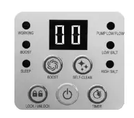
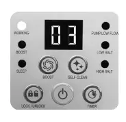
- Startup the unit: Plug the power cord into the electrical outlet and test the household socket GFCI (circuit breaker). Press button. Flashing code “00” appears on the electronic control station’s LED, indicating that the unit is ready to be programmed.
- Set operating hours for the Saltwater system: With code “00” flashing, press the button to set the desired operating hours. See the “Operating Time Table” for the required operating hours related to each pool size. Pressing will increase the time from 01 to 12 hours maximum. If you have selected too many hours keep timer will now activate your Saltwater System, at the same time each day, for the number of hours you have set.
NOTE: The Saltwater System will not operate if the filter pump is not operating. Make sure to program your filter pump (or start it manually) for operation beginning 5 minutes before the saltwater system and finishing 15 minutes after the saltwater system.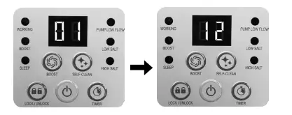
- Lock keypad controls: With the desired hour value showing, press button. A green “WORKING” indicator on the control panel will light up within a few seconds to indicate that the saltwater system has started sodium hypochlorite production, the LED will display the remaining chlorinator hours until it’s finished. Locking the control buttons into this setting prevents unauthorized changing of the operating cycle. NOTE: If you forget to lock the keypad controls, the system will automatically lock it and start working 10 seconds later.
- Readjust operating time if necessary: The operating hours can be re-adjusted if necessary. Press and the current programmed time will flash. Repeat steps 3 to 4.
- Stand-by/power saving mode:• When the cycle ends, the green “SLEEP” indicator on the control panel lights up and the LED display flashes “93”. The system is now in Stand-By mode. After a while, it shuts down and sets itself in a Power Saving mode. The system will automatically turn itself back on in 24 hours, starting its daily cycle of sodium hypochlorite production.
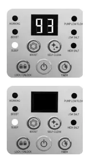
- The “SLEEP” indicator stays on, while the system is in the Power Saving mode.
- The LED display, however, goes blank after 5 minutes. Press any button ( or ) to view the last LED code.
Set BOOST operating hours:
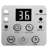
- button to unlock the keypad. With LED flashing, press the button to set the desired operating hours. Total of 4 settings: 36 hours, 48 hours, 60 hours and 00 (OFF). Keep pressing button to repeat the cycle.
- With the desired hour value showing, press the button to lock the keypad controls. The BOOST indicator will light up when activated. The system is now starting more sodium hypochlorite sanitizer production. After the boost procedure has been completed, the system will automatically switch to the normal working mode. The LED display will show the remaining BOOST hours first until it’s finished and then the remaining programmed saltwater system hours. NOTE: If you forget to lock the keypad controls, the system will automatically lock it and start working 10 seconds later.
- To cancel the boost cycle, press the button to unlock the keypad, then press a button and reset the hour to “00”.
Set electrode Self-Clean cycle time:
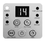
- The default self-clean cycle time is 14 hours. To adjust the self-clean cycle time:Press the button to unlock the keypad and the LED display is flashing. Depending on your pool water calcium hardness level, press the button to select the self-clean cycle time as below. Total of 3 settings: 14 hours, 10 hours and 06 hours. NOTE: The life of the cell varies depending on water conditions, pool usage, and operating time of the device. Select 14 hours cycle time to maximize the life of the electrolytic cell if the calcium hardness level is up to 150 ppm. Manual routine cleaning and maintenance will further lengthen the life of the electrolytic cell.
- With the desired self-clean hours showing, press the button to lock the keypad controls and the LED display will return to the normal operating time. The system will reverse the polarity of the electrode (7) every time according to the selected hours. NOTE If you forget to lock the keypad controls, the system will automatically lock it and start working 10 seconds later.
LED CODE CHART
IMPORTANT
When Code “90” alarm is shown, ensure the timer of the filter pump is set one (1) hour longer than the Saltwater System. If the filter pump does not have a built-in timer, the filter pump needs to be turned on/off manually every day.
MAINTENANCE
IMPORTANT
Unplug the power cord before cleaning your system. Also insert the black hat-like plugs in the strainer opening to prevent water spillage. After completing all maintenance tasks, you must plug the power cord back in and remove the plugs.
Titanium Electrode Cleaning
The titanium electrode has a self-cleaning function incorporated into the electronic control’s programming. In most cases, this self-cleaning action will keep the electrode working at optimum efficiency. If the pool water is hard (high mineral content) the electrode may require periodic manual cleaning. To maintain maximum performance, we recommend that you open and visually inspect the titanium electrode (7) monthly.
The following steps provide instructions on how to clean your cell.
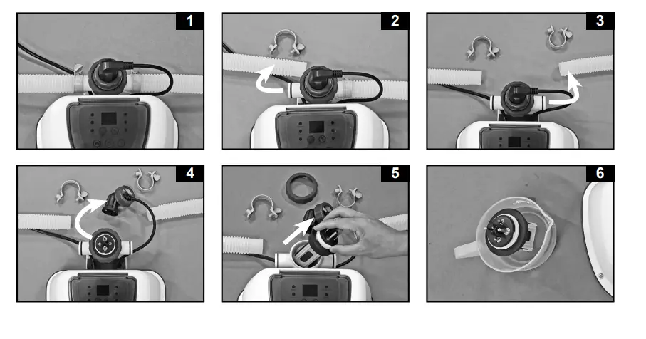
Inspection and cleaning:
- Switch off the unit, unplug the power cord from the electrical socket.
- To prevent water from flowing out of the pool, unscrew the strainer grids from the strainer connectors and insert the hat-like plugs into the strainer connectors.
- Disconnect the 2 hoses from the Saltwater System (see drawings 1~3).
- Unscrew the titanium electrode plug collar, disconnect the plug from the titanium electrode (7) (see drawing 4).
- Unscrew the cell nut, remove the titanium electrode from the cell housing (see drawing 5).
- Place the titanium electrode in a container and pour kitchen-grade vinegar into the container until the titanium electrode is immersed. Soak for 1 hour and then flush with a high-pressure garden hose (see drawing 6).
- Reverse steps 3, 4, 5, and 6 to reconnect the electrolytic cell.
INTEX® TEST STRIPS (PACKED WITH THE PRODUCT)
The Test Strips can test the “Free Chlorine”, “pH”, “Calcium Hardness” and “Total Alkalinity” levels at the same time. We recommend that you test the water chemistry weekly, and maintain the chlorine concentration at 1.0-3.0 ppm.
Directions and Use
- Dip the entire strip into the water and remove immediately.
- Hold the strip level for 15 seconds. Do not shake excess water from the strip.
- Now compare the strip pad to the color chart on the packaging label. If necessary, adjust the chemical level in the pool water. It is very important, to use the proper technique when testing the water’s chemical level. Read and follow the written strip instructions carefully.
LONG TERM STORAGE
- Disconnect the power cord from the electrical outlet.
- After the pool is completely empty, disconnect the Saltwater System from the hoses by reversing the installation instructions.
- Air-dry the unit before you store it. This might be a good time to visually inspect and clean the electrolytic cell.
- Store the unit and accessories in a dry place. The temperature should be controlled, between 32 degrees Fahrenheit (0 degrees Celsius) and 97 degrees Fahrenheit (36 degrees Celsius).
- The original package can be used for storage.
POOL MAINTENANCE & CHEMICAL DEFINITIONS
| Preferred Water Chemistry Reading | |||
| Minimum | Ideal | Maximum | |
| Free Chlorine | 0 | 1.0 – 3.0 ppm | 5.0 ppm |
| Combined Chlorine | 0 | 0 ppm | 0.2 ppm |
| ph | 7.2 | 7.4 – 7.6 | 7.8 |
| total Alkalinity | 40 ppm | 80 ppm | 120 ppm |
| Calcium hardness | 50 ppm | 100 – 250 ppm | 350 ppm |
| Stabilizer (Cyanuric Acid) | 10 ppm | 10 – 30 ppm | 30 ppm |
| Free Chlorine – Is the chlorine residual present in pool water. |
| Combined Chlorine – Is formed by the reaction of free chlorine with ammonia wastes.
Result if too high – Sharp chlorinous odor, eye irritation. |
| ph – A value that indicates how acidic or basic a solution is.
Result if too low – Corroded metals, eye & skin irritation, destruction of total alkalinity. Result if too high – Scale formation, cloudy water, shorter filter runs, eye & skin irritation, poor chlorine efficiency. |
| total Alkalinity – Indicates the degree of the water’s resistance to change in pH. It determines the speed and ease of pH change, so always adjust total alkalinity before adjusting the pH level.
Result if too low – Corroded metals, eye & skin irritation. Low alkalinity will cause the pH to be unstable. Any chemical added to the water will have an affect on pH. Result if too high – Scale formation, cloudy water, eye & skin irritation, poor chlorine efficiency. |
| Calcium hardness – Refers to the amount of calcium and magnesium dissolved in the water.
Result if too high – Eye & skin irritation, difficulty balancing water and poor chlorine efficiency. Scale will form and will cause the water to become cloudy. |
| Stabilizer – Stabilizers extend the life of chlorine in swimming pools.
(Cyanuric Acid) |
- Do not add pool chemicals directly to the skimmer. This may damage the cell.
- Maintaining a salt and sanitizer level above the recommended range can contribute to the corrosion of the pool equipment.
- Check the expiry date of the test kit as the test results may be inaccurate if the kit is used after that date.
- If, due to heavy pool usage, it is required to increase the sanitizer level, then use a chemical-based on Trichloro-s-triazinetrione or sodium dichloro-s-triazinetrione dihydrate.
TROUBLESHOOTING GUIDE
| TROUBLESHOOTING GUIDE | ||
| PROBLEM | CAuSE | SOLutION |
| INSUFFICIENT SODIUM HYPOCHLORITE | • Insufficient operating hours of the Saltwater System.
• The salt level in the pool water is less than 2000ppm. This is insufficient. • Sodium hypochlorite loss due to intense sunlight exposure. • The bather load has increased. • Clogged or dirty electrolytic cell. • High UV level exposure. |
• Increase the daily Saltwater System operating time. See “Operating Instructions”.
• Check the salt level with the Test Kit. Adjust as needed. See “Salt & Pool Water Volumes”. • Use a pool cover when the pool is not in use and/or when the unit is operating. • Increase the daily Saltwater System operating time. See “Operating Instructions”. • Remove the cell for inspection, clean it if necessary. See “Maintenance”. • Cover the pool with a pool cover for 2 days with the device running and then test the water using the test strips. • If the pool is clean and clear, add stabilizer to the water and then test the water with the device running. |
| WHITE FLAKES IN THE WATER | • Excessive calcium hardness is present in the pool water. | • Drain about 20 to 25% of the pool water and add fresh water to decrease the calcium hardness. Inspect the electrolytic cell for scale buildup. Clean the electrolytic cell if necessary. |
| NO LED DISPLAY | • No power supply.
• Household socket GFCI has not reseted. • A power fuse has blown. • LED failure. |
• Find out the switch and turn on.
• Reset the household socket GFCI. • Contact Intex Service Center. • Contact Intex Service Center. |
| This device complies with part 15 of the FCC Rules. Operation is subject to the following two conditions: (1) This device may not cause harmful interference, and (2) this device must accept any interference received, including interference that may cause undesired operation.
WARNING: Changes or modifications not expressly approved by the party responsible for compliance could void the user’s authority to operate the equipment. NOtE: This equipment has been tested and found to comply with the limits for a Class B digital device, pursuant to part 15 of the FCC Rules. These limits are designed to provide reasonable protection against harmful interference in a residential installation. This equipment generates, uses and can radiate radio frequency energy and, if not installed and used in accordance with the instructions, may cause harmful interference to radio communications. However, there is no guarantee that interference will not occur in a particular installation. If this equipment does cause harmful interference to radio or television reception, which can be determined by turning the equipment off and on, the user is encouraged to try to correct the interference by one or more of the following measures: • Reorient or relocate the receiving antenna. • Increase the separation between the equipment and the receiver. • Connect the equipment into an outlet on a circuit different from that to which the receiver is connected. • Consult the dealer or an experienced radio/TV technician for help. |
||
| TROUBLESHOOTING GUIDE (continued) | ||
| LED PANEL CODE | PRObLEM | SOLutION |
| LED Panel Code Flash & Alarm On (NOtE: Always turn off the power before cleaning and servicing). | ||
| 1. Filter pump not attached to system and/or switch on. | • Ensure a filter pump with the correct flow rate is attached and operating. See “Setup Instruction”. | |
| 2. Circulation line is blocked. | • Remove the black hat-like plugs from the pool strainer connectors.
• Clear your filter cartridge and cell from debris and dirt. See “Maintenance”. • Release all trapped air in the circulation line. See the filter pump manual. |
|
| 3. Incorrect inlet and outlet hose direction. | • Check the direction of the inlet and the outlet hose. Reverse the hoses if necessary. See “Set Up Instructions”. | |
| 4. Scale on flow sensor pins inside the titanium electrode. | • Clean the titanium electrode. See “Maintenance” section. | |
| 5. Electrode cord is loose. | • Plug the cord into the electrode and tighten the plug collar firmly. | |
| 6. Inner timer conflict between
filter pump and saltwater system. |
• Reset both timers on the filter pump and saltwater system. See “Operating Instructions”. | |
| 1. Dirt or scale on titanium plates. | • Remove the electrolytic cell for inspection. Clean it if necessary. See “Maintenance”. | |
| 2. Low salt level / No salt. | • Add salt. See “Salt & Pool Water Volumes”. | |
| 3. Electrolytic cell cord is loose. | • Ensure that the cell cord is plugged firmly into the cell housing receptacle. | |
| 4. Possible electrolytic cell failure. | • Contact Intex Service Center. Replace the cell if needed. | |
| 1. High salt level.
2. Water temperature > 35ºC. 3. Titanium electrode failure. |
• Partially drain the pool and refill it with fresh water. See “Salt & Pool Water Volumes”.
• Contact Intex Service Center. • Contact Intex Service Center. |
|
| IMPORtANt
If you continue to experience difficulty, please contact our Consumer Service Department for assistance. See separate “Authorized Service Centers” sheet. |
||
IMPORTANT
If you continue to experience difficulty, please contact our Consumer Service Department for assistance. See separate “Authorized Service Centers” sheet.
LIMITED WARRANTY
Your Krystal Clear Saltwater System® has been manufactured using the highest quality materials and workmanship. All Intex products have been inspected and found free of defects prior to leaving the factory. This Limited Warranty applies only to the Krystal Clear Saltwater System® and accessories listed below. The provisions of this Limited Warranty apply only to the original purchaser and is not transferable. This Limited Warranty is valid for the period noted below from the date of the initial retail purchase. Keep your original sales receipt with this manual, as proof of purchase will be required and must accompany warranty claims or the Limited Warranty is invalid.
- Krystal Clear Saltwater System® Warranty – 2 Years Titanium electrode Warranty – 1 Year Hoses & Fittings Warranty – 180 days
If a manufacturing defect is found within the periods noted above, please contact the appropriate Intex Service Center listed in the separate “Authorized Service Centers” sheet. The Service Center will determine the validity of the claim. If the Service Center directs you to return the product, please carefully package the product and send it with shipping and insurance prepaid to the Service Center. Upon receipt of the returned product, the Intex Service Center will inspect the item and determine the validity of the claim. If the provisions of this warranty cover the item, the item will be repaired or replaced at no charge.
Any and all disputes regarding the provisions of this Limited Warranty shall be brought before an informal dispute settlement board and unless and until the provisions of these paragraphs are carried forth, no civil action may be instituted. The methods and procedures of this settlement board shall be subject to the rules and regulations set forth by the Federal Trade Commission (F.T.C.). IMPLIED WARRANTIES ARE LIMITED TO THE TERMS OF THIS WARRANTY AND IN NO EVENT SHALL INTEX, THEIR AUTHORIZED AGENTS OR EMPLOYEES BE LIABLE TO THE BUYER OR ANY OTHER PARTY FOR DIRECT OR CONSEQUENTIAL DAMAGES OR LIABILITIES. Some states or jurisdictions do not allow the exclusion or limitation of incidental or consequential damages, so the above limitation or exclusion may not apply to you.
This Limited Warranty does not apply if the products are subject to negligence, abnormal use or operation, accident, improper operation, improper voltage or current contrary to operating instructions, or to damage by circumstances beyond Intex’s control, including but not limited to, ordinary wear and tear and damage caused by exposure to fire, flood, freezing, rain, or other external environmental forces. This Limited Warranty applies only to those parts and components sold by Intex. The Limited Warranty does not cover unauthorized alterations, repairs, or disassembly by anyone other than Intex Service Center personnel.
DO NOT GO BACK TO THE PLACE OF PURCHASE FOR RETURN OR REPLACEMENT. IF YOU ARE MISSING PARTS OR NEED ASSISTANCE, PLEASE CALL US TOLL-FREE (FOR U.S. AND CANADIAN RESIDENTS): 1-800-234-6839 OR VISIT OUR WEBSITE: WWW.INTEXCORP.COM. Proof of Purchase must accompany all returns or the warranty claim will be invalid.