Wireless HDMI Transmitter and Receiver Kit

Quick Start Guide
GWHD11
PART NO. Q1292-b
www.iogear.com
Package Contents
1 x Wireless HDMI Transmitter
1 x Wireless HDMI Receiver
1 x Mini USB to USB Cable
2 x USB Power Adapters
1 x Remote Control
2 x AAA Battery
1 x HDMI Cable
1 x Quick Start Guide
1 x Warranty Card
System Requirements
Display:
- TV or Projector
- HDMI Input
Media Source:
- HDMI Output
Optional: Additional Wireless HDMI Transmitters (up to 3 additional units), sold separately Part# GWHDSTX
Overview
Wireless HDMI Transmitter:
- LED Status Indicator: – Solid blue when powered on and wireless link established – 1 flash/sec when in pairing mode – 3 flashes/sec when establishing the link with the Receiver
- HDMI Output Connector
- Pairing Button
- Mini USB Power Jack

Overview
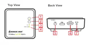
Wireless HDMI Receiver:
- Power Button with LED Indicator: – Lights green when powered on – – Lights red when in Standby Mode or when pairing
- Source Button
- Video Status LED – Off when in Standby Mode – Blinks at initial boot up / warm up (15~20 seconds) – When in wireless linked mode: a. Blinks quickly when there’s no input from a selected source b. Blinks slowly when the video format is not recognized c. Static green when the video format is recognized
- Wireless Status LED – Off when in Standby Mode – Blinks at initial boot up / warm up – Blinks when searching for available channels – Static green when in wireless linked mode
- Mini USB Power Jack
- HDMI Output (To Display HDMI Connector)
Hardware Installation
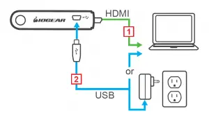
Step 1: Setup the Wireless HDMI Transmitter
- Power on your PC or media source (Bluray, Sattelite box, etc.)
- Power the transmitter through one of two options: a. If used with a Blu-Ray player or similar device, connect the Wireless HDMI Transmitter to the USB power adapter first, then plug the transmitter’s HDMI connector into the Blu-Ray HDMI output port. b. If used with a computer, connect the Mini USB connector of the power cable to the transmitter’s Mini USB port and USB-A connector (the other end of the power cable) to the USB port on the computer.
- Connect the Wireless HDMI Transmitter to the HDMI output port of the computer or media source.
- The LED will start to flash to start the pairing process, once paired the LED will turn solid. Please note that this process could take up to 1 minute.
Step 2: Setup the Wireless HDMI Receiver
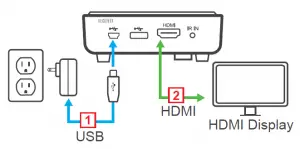
- Power on the TV / projector.
- Connect the USB power adapter to the Mini-USB power jack on the receiver and a wall outlet for power supply.
- Connect the HDMI cable to the HDMI connector on the receiver and to the HDMI Input on the TV / Projector.
- LEDs for wireless and video will start to flash. The wireless LED will turn solid and then the video LED will turn solid
- Once the link has been established between the transmitter and receiver, video from the connected computer or HDMI media source will be displayed on the TV / Projector. The connection could take up to a minute to be established.
Computer Display Setting
You can adjust your display by going to your computer screen resolution preferences to change the display setting to “Duplicate,” “Extend” or “Project Only” on your HDTV / HD projector.

If all operation is normal, the LED lights on both should be static (not blinking).
Pairing Additional Transmitters
The Wireless HDMI Receiver can be paired with up to 3 additional Wireless HDMI Transmitters (Part #GWHDSTX sold separately). Please visit http://www.iogear.com/product/GWHDSTXB/ for more information.
Note: When adding an additional transmitter:
1. Look at your serial numbers to see if * mark precedes the serial number on the receiver. If there is a *, the transmitter MUST also have * mark precedes the serial number or the transmitter and the receiver will not pair. Conversely if there is no * mark before the serial number of the receiver, then the transmitter must also be absent of the * mark before the serial number.
2. Make sure that the power to any existing transmitters already linked to the receiver is powered off before entering the receiver into pairing mode.
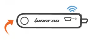
Pairing Mode for the Transmitter:
1. Once the transmitter is connected to the computer or source player and is powered on, the LED will start to blink fast. Press and hold the Pairing Button. You can now release the pairing button
2. The transmitter is in Pairing Mode once the Power LED flashes slowly (1 flash/sec).
Pairing Mode for the Receiver:
1. Once the receiver is connected to the HDTV or HD projector and is powered on, press the Transmitter No. button on the Remote Control.
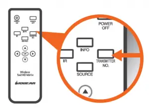
2. The On-screen Display (OSD) will appear on the HDTV / HD projector. Use the UP or DOWN buttons to select SETUP menu.
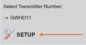
3. Select Add New Transmitter to search for an available transmitter.
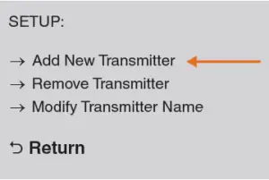
The OSD will display Searching…
SEARCHING……
Pairing Additional Transmitters
The Power LED on the receiver will flash ORANGE when it is in Pairing Mode.
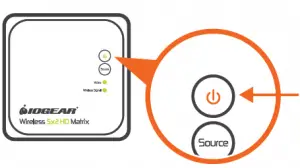
In the event that you need to exit Searching Mode, press the Transmitter No. button on the remote control.

4. When both the transmitter and receiver are in Pairing Mode, they will search for each other and automatically pair.

5. After the pairing is complete, both the transmitter and receiver will re-boot and establish the link to each other automatically.
Re-pairing Transmitter to Receiver
1. If the transmitter and receiver lose their linked connection, follow the steps for Pairing Additional Transmitter to re-establish the connection.
Modifying Transmitter Name
If more than one transmitter is linked to the receiver, use the following steps below to modify a transmitter’s name:
1. Press Transmitter No. to display the list of linked transmitters.

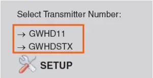
2. Select SETUP menu by using the Up / Down buttons; press OK to select.

3. Select Modify Transmitter Name option to change a transmitter’s name.
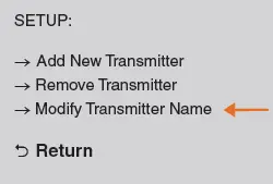
4. Use the Up / Down buttons to select the transmitter you want to modify.
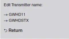
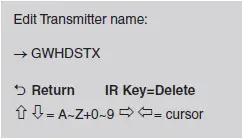
5. Then use the Up / Down buttons on the remote to select alphanumeric characters; use the Left / Right buttons on the remote to move the cursor; Press IR button to backspace.
Switching between Transmitters
1. Press the Transmitter No. button. The OSD will show a list of transmitters linked to the receiver.

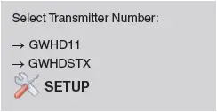
2. Use the Up / Down buttons to select the transmitter you want to display on your HDTV / HD projector. Then press OK and allow ~10-12 seconds for the receiver and transmitter to re-establish a connection.
Removing a Paired Transmitter
1. Press Transmitter No. to display the list of linked transmitters.


2. Select SETUP menu by using the Up / Down buttons; press OK to select.
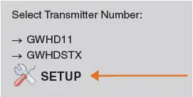
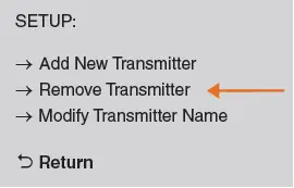
3. Select Remove Transmitter option.
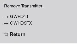
4. Use the Up / Down arrow buttons to select the transmitter to be removed and press OK.
Warranty
Warranty Information This product carries a 1 Year Limited Warranty. For the terms and conditions of this warranty, please go to https://www.iogear.com/support/warranty
Register online at https://www.iogear.com/register
Important Product Information Product Model Serial Number
Contact
WE’RE HERE TO HELP YOU! NEED ASSISTANCE SETTING UP THIS PRODUCT?
Make sure you: 1. Visit www.iogear.com for more product information 2. Visit www.iogear.com/support for live help and
product support
IOGEAR https://iogear.custhelp.com [email protected] www.iogear.com
Compliance Information
Federal Communication Commission Interference Statement
This equipment has been tested and found to comply with the limits for a Class B digital service, pursuant to Part 15 of the FCC rules. These limits are designed to provide reasonable protection against harmful interference in a residential installation. Any changes or modifications made to this equipment may void the user’s authority to operate this equipment. This equipment generates, uses, and can radiate radio frequency energy. If not installed and used in accordance with the instructions, may cause harmful interference to radio communications. However, there is no guarantee that interference will not occur in a particular installation. If this equipment does cause harmful interference to radio or television reception, which can be determined by turning the equipment off and on, the user is encouraged to try to correct the interference by one or more of the following measures:
– Reorient or relocate the receiving antenna – Increase the separation between the equipment and receiver – Connect the equipment into an outlet on a circuit different from
that to which the receiver is connected – Consult the dealer or an experienced radio/TV technician for help
FCC Caution: Any changes or modifications not expressly approved by the party responsible for compliance could void the user’s authority to operate this equipment.
IOGEAR Video Capture Adapter / HDMI® to USB-C™ Quick Start Guide
GUV301
PART NO. Q1569
Package Contents
1 x GUV301
1 x USB-C to USB-A Adapter
1 x Quick Start Guide
1 x Warranty Card
The terms HDMI, HDMI High-Definition Multimedia Interface, and the HDMI Logo are trademarks or registered trademarks of HDMI Licensing Administrator, Inc.
System Requirements
Operating System:
Windows 7 and above with UVC v1.1 support
Mac OSX 10.13+ with UVC support
(UVC = USB Video Class)
System Requirement:
CPU: Intel® CoreTM i3 Core 2.8 GHz or higher
Memory: 4GB or more
One USB-A or USB-C 3.1 port
Stream software with UVC device support
Stream Software Support*:
*Above lists some examples of supported video recording/live streaming software. The listed examples are for reference only and are not affiliated in any way with IOGEAR or ATEN. All trademarks are property of their respective owners.
Overview
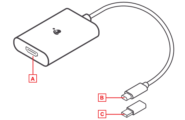
A. HDMI Port
B. USB-C Connector
C. USB-C to USB-A Adapter
Installation
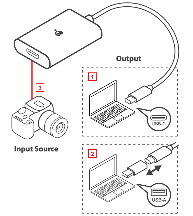
- Power on your host (e.g. laptop) and connect the USB-C Connector to the host.
- If your laptop only has a USB-A interface, connect the (included) USB-C to USB-A adapter between the host and the USB-C Host connector.
- Connect your HDMI source device to the GUV301 HDMI port**.
- Please download and install stream software from “Stream Software Support list” to enable recording or streaming function for GUV301.
**GUV301 cannot display or capture HDCP protected content

Quick Start Guide Wireless 3D Digital Kit
Package Contents
1 x Wireless 3D Transmitter
| General Specifications | |||
| Supported Video Resolutions | HDMI Input | 1080p, 1080i, 720p, 576p, 480p | |
| Supported Audio Formats | Digital Audio | Up to 6 Mbps AC3 and DTS | |
| Transmission Distance | The maximum video transmission range is 100 feet.* If you have more than one pair, each transmitter and receiver should be at least 6.5 feet away from one another. |
||
| Antenna | High-Performance Internal Antennas | ||
| Operating Frequencies | 4.9 ~ 5.9GHz (Include non-DFS and DFS Frequency Bands) | ||
| Power Supply | 100 ~ 240V AC in, 5V DC out Power Adaptor | ||
| Operating Temperature | 32° ~104°F | ||
| Interfaces | Transmitter | Receiver | |
| A/V | HDMI Input | Two (Type A) | – |
| Interfaces | HDMI Output | One (Type A) | One (Type A) |
| IR
Control |
IR Senso | Yes | Yes |
| Extender | 2.5mm Jack; 33KHz ~ 40KHz | – | |
| Power
Interface |
Power Input | 5V DC Jack | 5V mini USB |
| Switches | Power Switch | Yes (One Tack Switch) | Yes (One Tack Switch) |
| Source Switch | Yes (One Tack Switch) | Yes (One Tack Switch) | |
| LEDs | Power LED | 1 x LED (Blue/Red) | 1 x LED (Blue/Red) |
| Source LED | 2 x Blue LED | 2 x Blue LED | |
| Signal Status | – | OSD Displayed | |
| Dimensions (W) x (L) x (H) | 7.25” x 3.75” x 1.25” | 3.75” x 3.75” x 1.25” | |
*Distances may vary depending on environment; solid objects such as steel, concrete, and brick may view shorter distances
HDMI, the HDMI Logo, and High-Definition Multimedia Interface are trademarks of HDMI Licensing LLC.
Device Overview
Front
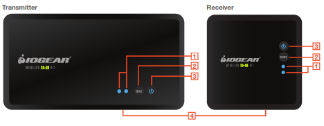
1. Source Indicator – The solid blue LED indicator shows the active media source
2. Source Selection Button – Press to switch the media source of the transmitter
3. Power Button with LED Indicator – Press to turn the transmitter on or off
4. IR Sensor – See IR Blaster section for details
Back
 1. Tripod Bracket
2. DC – Power adapter socket
3. HDMI 1 – HDMI media source 1
4. HDMI 2 – HDMI media source 2
5. HDMI OUT – HDMI loop-through port for local TV connection (for 2 TV set-up)
6. IR OUT – IR blaster cable port (optional)
7. SERVICE – Reserved for manufacturer service purposes
8. Mini USB – Power adapter socket
9. HDMI – HDMI output port for TV connection
Remote
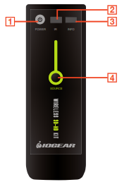
1. Power – Press to turn both receiver and transmitter on or off.
2. IR – Press to switch the IR Blaster frequency to meet the media source device’s requirement. Please refer to your device’s IR specifications.
3. INFO – Press to show on-screen-display (OSD) information on your Receiver TV. Press again to exit.
4. SOURCE Selection – Press to switch media source of the transmitter
Installation
Before you begin the installation:
- Turn off your TV and all HDMI devices. Ensure you have enough HDMI cables for all devices and there are enough electrical outlets nearby to power all of your devices.
- Position your Transmitter and Receiver up to 100 feet away from each other*. Test the placement for a good signal prior to permanently installing or mounting everything.
- For best performance and range, place the receiver where you have a clear view between the Transmitter and Receiver. Do NOT install the Receiver unit behind/below the TV or other metal devices where the wireless signal may experience interference. Do NOT install the Transmitter unit behind/below the Media sources, cabinet, or other metal devices where the wireless signal may experience interference.
- Do not block any ventilation openings or install near any heat sources such as radiators, AV receivers, stoves, or other devices that produce heat.
- The included devices shall not be directly exposed to any liquids.
Transmitter Setup
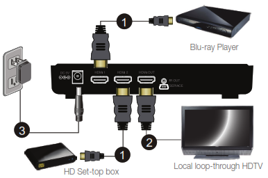
- Connect your source devices to the transmitter’s “HDMI IN” ports with HDMI cables (not included). See IR Blaster section for IR blaster installation (optional)
- For Two TV set-up, connect the local TV to the transmitter’s “HDMI OUT” for the loop-through connection.
- Connect the power adapter to the DC socket of the transmitter to power up the transmitter. The power LED blinks in blue initially to search for the connection (when the unit is powered off, the LED changes to Red).
Receiver Setup
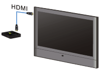
- Connect your TV to the HDMI port of the receiver with the included HDMI cable. Please choose the appropriate “HDMI” input source on your TV.
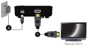
- Connect the supplied power adapter to the mini USB port of the receiver to power up the receiver. If the kit is in Standby mode (Both transmitter and receiver POWER LEDs are solid red), press the POWER button from either Transmitter or Receiver will turn on the whole kit.
- During the boot-up, the POWER LED will blink in blue until the Transmitter and the Receiver are wirelessly connected. This may take up to 20 seconds to establish the connection.
Basic Operation
- Turn on your TV and select the HDMI source input to which the receiver is connected.
- Turn on your source device and press the SOURCE button on the remote control or on the top of the receiver/transmitter to select the specific source device (HDMI 1 or HDMI 2).
- The POWER LED should stay in solid blue and you will see the video being broadcasted from your device. If not, please press “INFO” on the remote control and refer to the on-screen display (OSD) information below and the troubleshooting section.
IR Blaster (Optional)
The Receiver can also send RF signals to the Transmitter. This means that you do not have to point your remote control at your devices as you may be watching TV in a different location. Simply point your device’s remote control at the receiver side and the Transmitter sends IR commands to other devices allowing you to control your Blu-ray player or set-top box remotely.
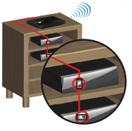
1. Plug the IR blaster cable into the IR OUT port of the transmitter.
2. Refer to your devices’ user manual and locate the IR sensor. Manually move the IR blaster to identify a good position of IR response. Securely place the IR blaster.
3. When the connection is established, the Transmitter relays infrared commands from your Receiver to devices. You may need to change the IR frequency to meet your devices’ IR specifications. See Troubleshooting for details.
Troubleshooting
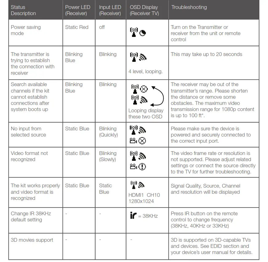
EDID Management
EDID (Extended Display Identification Data) is the data provided by digital displays to indicate their capabilities to video sources.
The Wireless 3D Digital Kit distributes HDMI signals from your video source to two HDMI displays. In order to deliver the best audio and video formats supported by both TVs, the kit reads the EDID information from both displays and determines the “Best Common” video resolutions and audio format to send to the video source to program EDID on the device (i.e. Blu-ray player’s auto resolution setting)
In order to output the best common resolution, the kit reads the EDID whenever a TV is plugged in, unplugged, or turned on/off. You will see both TVs flash couple of seconds in order to adjust the “Best Common” resolution that all devices can handle.
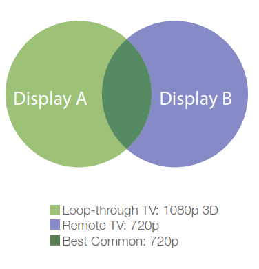
To get the best resolution for a specific TV (i.e. 1080p 3D), you can manually change the resolution from your video source or unplug the lower EDID devices then power cycle the kit and devices. For certain 3D Blu-ray players, you may need to eject and insert the 3D Blu-ray disc. Since your video source is not outputting the best common resolution, one of your TVs may not show any content or play audio-only. Please refer to your devices’ user manuals for further instructions.
Loop-through TV: 1080p 3D Remote TV: 720p Best Common: 720p
Mounting the Receiver to the Wall
Stud mounting is recommended. Use proper hardware for your wall type (such as anchors for drywall). When in doubt, consult your local hardware store. Please use caution and wear proper protection for your safety.
Industry Canada Statement
This device complies with RSS-210 of the Industry Canada Rules. Operation is subject to the following two conditions: (1) This device may not cause harmful interference, and (2) this device must accept any interference received, including interference that may cause undesired operation.
Ce dispositif est conforme à la norme CNR-210 d’Industrie Canada applicable aux appareils radio exempts de licence. Son fonctionnement est sujet aux deux conditions suivantes: (1) le dispositif ne doit pas produire de brouillage préjudiciable, et (2) ce dispositif doit accepter tout brouillage reçu, y compris un brouillage susceptible de provoquer un fonctionnement indésirable.
IMPORTANT NOTE: (IC: 9078A-ZRF31200)
Radiation Exposure Statement:
This equipment complies with IC radiation exposure limits set forth for an uncontrolled environment. This equipment should be installed and operated with a minimum distance of 20cm between the radiator & your body.
Caution:
(i) the device for operation in the band 5150-5250 MHz is only for indoor use to reduce the potential for harmful interference to co-channel mobile satellite systems;
(ii) high-power radars are allocated as primary users (i.e. priority users) of the bands 5250-5350 MHz and 5650-5850 MHz and that these radars could cause interference and/or damage to LE-LAN devices.
Federal Communications Commission (FCC) Statement
This equipment has been tested and found to comply with the limits for a Class B digital device, pursuant to Part 15 of the FCC Rules. These limits are designed to provide reasonable protection against harmful interference in a residential setting. This product generates, uses, and can radiate radio frequency energy and, if not installed and used as directed, it may cause harmful interference to radio communications. Although this product complies with the limits for a Class B digital device, there is no guarantee that interference will not occur in a particular installation.
CE Compliance
This device has been tested and found to comply with the following European Union directives: Electromagnetic Capability (89/336/EMC), Low Voltage (73/23/EEC) and R&TTED (1999/5/EC).
Limited Warranty
WE’RE HERE TO HELP YOU!
NEED ASSISTANCE SETTING UP THIS PRODUCT?
Make sure you:
- Use the live chat at www.iogear.com to try and solve any issues you may be having with the product
- Visit the Tech Info Library/FAQ on www.iogear.com (under the Support tab)
- Call the tech support line at 1-866-946-4327 (U. S. Only) or 949-453-8782
Warranty Information
This product carries a 1 Year Limited Warranty. For the terms and conditions of this warranty, please go to http://www.iogear.com/support/warranty or call 1-866-946-4327
Register online at http://www.iogear.com/register
Important Product Information
Product Model…….
Serial Number………
Limited Warranty
Toll Free: 866-946-4327 (USA) Phone: 949-453-8782
Address: 19641 Da Vinci, Foothill Ranch, CA 92610, USA
Web Site: www.iogear.com E-mail: [email protected]
About Us
FUN
IOGEAR offers connectivity solutions that are innovative, fun, and stylish, helping people enjoy daily life using our high technology products.
GREEN
IOGEAR is an environmentally conscious company that emphasizes the importance of conserving natural resources. The use of our technology solutions helps reduce electronic waste.

 Quick Start Guide
Kaliber Gaming™
Wireless Gaming Keyboard and Mouse
GKM602R
PART NO: Q1307
Package Contents
| 1 x GKM602R Keyboard | 1 x USB Receiver | 1 x Quick Start Guide |
| 1 x GKM602R Mouse | 3 x AA Batteries | 1 x Warranty Card |
Requirements
- Windows Vista®, Windows® 7, Windows® 8, Windows® 8.1
- Mac OS X 10.3+*
- USB port
*Some function keys may not work with older Mac OS Systems
Overview
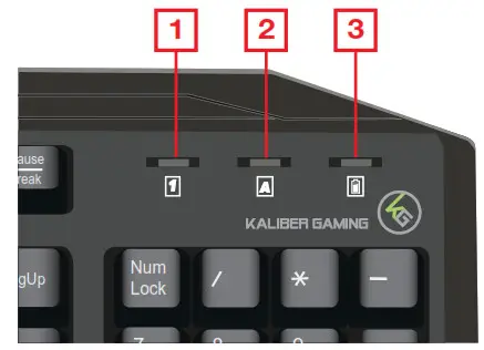
Keyboard Front View
- Num Lock LED turns on when Num Lock key is pressed
- Caps Lock LED turns on when Caps Lock key is pressed
- Low Power LED turns on when the power is less than 1.0V

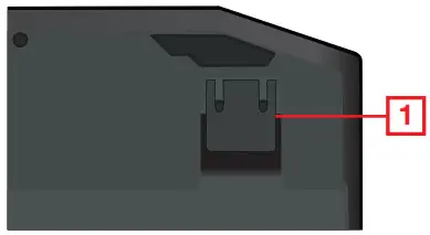
Keyboard Back View
- Foldable Legs - allow user to adjust the angle of keyboard
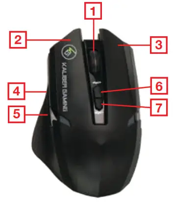
Mouse – Front View
- Scroll wheel/Middle button
- Left-click button
- Right-click button
- Fourth Button
- Fifth Button
- Adjust dpi setting up 1000/1500/2000
- Adjust dpi setting down 1000/1500/2000
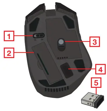
Mouse – Back View
- ON/OFF Switch
- Battery compartment
- IR sensor
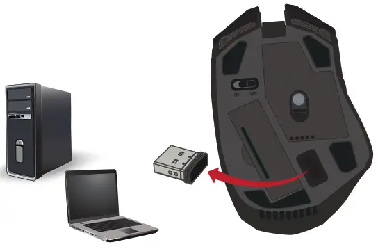
- USB Receiver
- USB Receiver
Hardware Installation
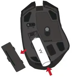
Mouse Battery Installation
- Switch mouse OFF
- Open the battery cover on the back of the mouse
- Insert the included AA battery into the battery tray
- Close the battery cover
- Switch mouse ON
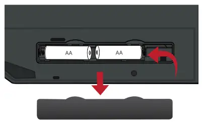
Keyboard Battery Installation
- Open the battery cover on the back of the keyboard
- Insert the included AA battery into the battery tray
- Close the battery cover
USB Receiver Installation
- Plug the USB Receiver into an available USB port on your computer
- Your operating system will start to install the device no additional software needed
DPI Setting
- GKM602R mouse factory default comes with 1000dpi.
- Choose desired dpi by pressing + button on mouse to increase dpi or
– button to reduce dpi
- Scroll wheel LED flash 1 time 1000dpi
- Scroll wheel LED flash 2 times 1500dpi
- Scroll wheel LED flash 3 times 2000dpi

Programmable Buttons

For a complete explanation of advanced setup and additional features, please download the GKM602R driver and instruction from www.IOGEAR.com/product/GKM602R
FCC Warning
![]() WARNING: This product may expose you to chemicals including styrene which is known to the State of California to cause cancer, birth defects or other reproductive harm. For more information, go to www.P65Warnings.ca.gov
WARNING: This product may expose you to chemicals including styrene which is known to the State of California to cause cancer, birth defects or other reproductive harm. For more information, go to www.P65Warnings.ca.gov
Federal Communication Commission Interference Statement
This equipment has been tested and found to comply with the limits for a Class B digital service, pursuant to Part 15 of the FCC rules. These limits are designed to provide reasonable protection against harmful interference in a residential installation. Any changes or modifications made to this equipment may void the user’s authority to operate this equipment. This equipment generates, uses, and can radiate radio frequency energy. If not installed and used in accordance with the instructions, may cause harmful guarantee that interference will not occur in a particular installation. If this equipment does cause harmful interference to radio or television reception, which can be determined by turning the equipment off and on, the user is encouraged to try to correct the interference by one or more of the following measures:
– Reorient or relocate the receiving antenna
– Increase the separation between the equipment and receiver
– Connect the equipment into an outlet on a circuit different from that to which the receiver is connected
– Consult the dealer or an experienced radio/TV technician for help
FCC Caution: Any changes or modifications not expressly approved by the party responsible for compliance could void the user’s authority to operate this equipment.
Limited Warranty
Warranty Information
This product carries a 3 Year Limited Warranty. For the terms and conditions of this warranty, please go to https://www.iogear.com/support/warranty
Register online at https://www.iogear.com/register
Important Product Information
Product Model______________________
Serial Number______________________
Contact
WE’RE HERE TO HELP YOU! NEED ASSISTANCE SETTING UP THIS PRODUCT?
Make sure you:
- Visit www.iogear.com for more product information
- Visit www.iogear.com/support for live help and product support
IOGEAR https://iogear.custhelp.com [email protected]
www.iogear.com


USB 2.0 External DVI Video Card
GUC2020DW6
External USB 2.0 to DVI Video Card
The IOGEAR USB 2.0 External DVI Video Card instantly adds an additional high resolution DVI display through your USB 2.0 port. Simply install the driver, plug the adapter into the USB 2.0 port and you’re ready to go.
Extend your Desktop for Increased Productivity
Extend your desktop across both displays allowing you to increase your productivity like never before. While reading email on one display, open attachments on the other display. Expand spreadsheets across both monitors; in graphics programs you can increase your working area by putting all your pallets on the second display.
Easily connect additional DVI monitors via USB 2.0 ports
Extend your desktop, or mirror content on two displays
Add up to six* external DVI video cards via USB 2.0 ports
Support resolution of UXGA 1600 x 1200 or HD 1920 x 1080 and 32-bit color
No need to open cases. Great for laptops or leasing computers
*Requires six USB 2.0 ports. Not recommended to connect with USB hubs.
The possibilities with the IOGEAR DVI display adapter are endless.
Office Use:
- View large spreadsheets across two screens with display continuity

Requirements
- Windows® 10, Windows® 8.1, Windows® 8, Windows® 7, Windows Vista® , Windows XP®
- Intel based Mac OS X 10.4 and above
- Available USB 2.0 port (not compatible with USB 1.x)
- DVI monitor or VGA monitor with DVI to VGA adapter
Package Contents
- 1 – USB to DVI Adapter
- 1 – DVI to VGA Adapter
- 1 – Quick Start Guide
- 1 – CD-ROM with User Guide and Installation Software
- 1 – 4 ft. USB 2.0 Cable
Specifications
Function
Power Consumption 5V
Video Resolution Max 1920 x 1080
Ports 1 Female DVI / 1 USB 2.0 Type mini-B
Operating Temperature 68 ~ 122 ?F ( 20 ~ 50 ?C)
Storage Temperature 32 ~ 158 ?F ( 0 ~ 70 ?C)
Operating System Support Windows XP, Windows Vista, Windows 7, Mac OS X v10.4 or later
USB Specification 2.0 compliant
Humidity 20-80% RH, (Non Condensing)
Power Switch Bus Powered
Video connections
Input USB
Output DVI
Connectors
USB 1
Video Output 1
Power Mode USB
Color Depth 32-bit true color
Unit Dimensions
Width 2.25 in
Height 0.8 in
Length 3.5 in
Inner Pack
Width 16.5 in. (42 cm)
Height 17 in. (43 cm)
Length 7 in. (17.8 cm)
Inner Pack Qty. 12
Unit Package Dimensions
Width 7.9 in (20 cm)
Height 7.9 in (20 cm)
Depth 2 in. (5.1 cm)
Master Carton
Width 17.13 in (43.5 cm)
Height 17.72 in (45 cm)
Depth 15.16 in (38.5 cm)
Master Carton Qty. 24
Weight
Master Carton Wt. 19 lbs.
Inner Pack Wt. 9.4 lb
Unit Pack Wt. 0.8 lbs
Unit Wt. w/accessories 0.35 lb
Unit Wt. 0.25 lb
www.iogear.com
Iogear USB 2.0 External DVI Video Card [GUC2020DW6] Datasheet – Optimized PDF
Iogear USB 2.0 External DVI Video Card [GUC2020DW6] Datasheet – Original PDF