
Quick Start Guide Wireless 3D Digital Kit
Package Contents
1 x Wireless 3D Transmitter
| General Specifications | |||
| Supported Video Resolutions | HDMI Input | 1080p, 1080i, 720p, 576p, 480p | |
| Supported Audio Formats | Digital Audio | Up to 6 Mbps AC3 and DTS | |
| Transmission Distance | The maximum video transmission range is 100 feet.* If you have more than one pair, each transmitter and receiver should be at least 6.5 feet away from one another. |
||
| Antenna | High-Performance Internal Antennas | ||
| Operating Frequencies | 4.9 ~ 5.9GHz (Include non-DFS and DFS Frequency Bands) | ||
| Power Supply | 100 ~ 240V AC in, 5V DC out Power Adaptor | ||
| Operating Temperature | 32° ~104°F | ||
| Interfaces | Transmitter | Receiver | |
| A/V | HDMI Input | Two (Type A) | – |
| Interfaces | HDMI Output | One (Type A) | One (Type A) |
| IR
Control |
IR Senso | Yes | Yes |
| Extender | 2.5mm Jack; 33KHz ~ 40KHz | – | |
| Power
Interface |
Power Input | 5V DC Jack | 5V mini USB |
| Switches | Power Switch | Yes (One Tack Switch) | Yes (One Tack Switch) |
| Source Switch | Yes (One Tack Switch) | Yes (One Tack Switch) | |
| LEDs | Power LED | 1 x LED (Blue/Red) | 1 x LED (Blue/Red) |
| Source LED | 2 x Blue LED | 2 x Blue LED | |
| Signal Status | – | OSD Displayed | |
| Dimensions (W) x (L) x (H) | 7.25” x 3.75” x 1.25” | 3.75” x 3.75” x 1.25” | |
*Distances may vary depending on environment; solid objects such as steel, concrete, and brick may view shorter distances
HDMI, the HDMI Logo, and High-Definition Multimedia Interface are trademarks of HDMI Licensing LLC.
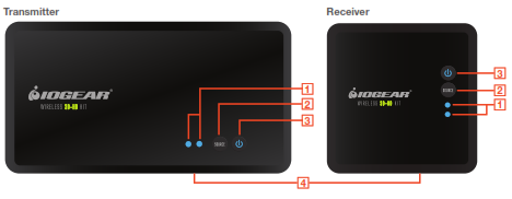
Device Overview
Front

1. Source Indicator – The solid blue LED indicator shows the active media source
2. Source Selection Button – Press to switch the media source of the transmitter
3. Power Button with LED Indicator – Press to turn the transmitter on or off
4. IR Sensor – See IR Blaster section for details
Back

2. DC – Power adapter socket
3. HDMI 1 – HDMI media source 1
4. HDMI 2 – HDMI media source 2
5. HDMI OUT – HDMI loop-through port for local TV connection (for 2 TV set-up)
6. IR OUT – IR blaster cable port (optional)
7. SERVICE – Reserved for manufacturer service purposes
8. Mini USB – Power adapter socket
9. HDMI – HDMI output port for TV connection
Remote

1. Power – Press to turn both receiver and transmitter on or off.
2. IR – Press to switch the IR Blaster frequency to meet the media source device’s requirement. Please refer to your device’s IR specifications.
3. INFO – Press to show on-screen-display (OSD) information on your Receiver TV. Press again to exit.
4. SOURCE Selection – Press to switch media source of the transmitter
Installation
Before you begin the installation:
- Turn off your TV and all HDMI devices. Ensure you have enough HDMI cables for all devices and there are enough electrical outlets nearby to power all of your devices.
- Position your Transmitter and Receiver up to 100 feet away from each other*. Test the placement for a good signal prior to permanently installing or mounting everything.
- For best performance and range, place the receiver where you have a clear view between the Transmitter and Receiver. Do NOT install the Receiver unit behind/below the TV or other metal devices where the wireless signal may experience interference. Do NOT install the Transmitter unit behind/below the Media sources, cabinet, or other metal devices where the wireless signal may experience interference.
- Do not block any ventilation openings or install near any heat sources such as radiators, AV receivers, stoves, or other devices that produce heat.
- The included devices shall not be directly exposed to any liquids.
Transmitter Setup
![]()
- Connect your source devices to the transmitter’s “HDMI IN” ports with HDMI cables (not included). See IR Blaster section for IR blaster installation (optional)
- For Two TV set-up, connect the local TV to the transmitter’s “HDMI OUT” for the loop-through connection.
- Connect the power adapter to the DC socket of the transmitter to power up the transmitter. The power LED blinks in blue initially to search for the connection (when the unit is powered off, the LED changes to Red).
Receiver Setup
- Connect your TV to the HDMI port of the receiver with the included HDMI cable. Please choose the appropriate “HDMI” input source on your TV.
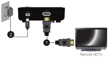
- Connect the supplied power adapter to the mini USB port of the receiver to power up the receiver. If the kit is in Standby mode (Both transmitter and receiver POWER LEDs are solid red), press the POWER button from either Transmitter or Receiver will turn on the whole kit.
- During the boot-up, the POWER LED will blink in blue until the Transmitter and the Receiver are wirelessly connected. This may take up to 20 seconds to establish the connection.

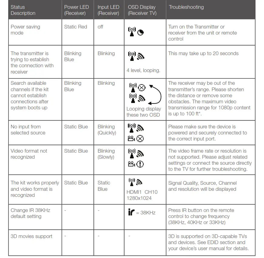
Basic Operation
- Turn on your TV and select the HDMI source input to which the receiver is connected.
- Turn on your source device and press the SOURCE button on the remote control or on the top of the receiver/transmitter to select the specific source device (HDMI 1 or HDMI 2).
- The POWER LED should stay in solid blue and you will see the video being broadcasted from your device. If not, please press “INFO” on the remote control and refer to the on-screen display (OSD) information below and the troubleshooting section.
IR Blaster (Optional)
The Receiver can also send RF signals to the Transmitter. This means that you do not have to point your remote control at your devices as you may be watching TV in a different location. Simply point your device’s remote control at the receiver side and the Transmitter sends IR commands to other devices allowing you to control your Blu-ray player or set-top box remotely.


1. Plug the IR blaster cable into the IR OUT port of the transmitter.
2. Refer to your devices’ user manual and locate the IR sensor. Manually move the IR blaster to identify a good position of IR response. Securely place the IR blaster.
3. When the connection is established, the Transmitter relays infrared commands from your Receiver to devices. You may need to change the IR frequency to meet your devices’ IR specifications. See Troubleshooting for details.
Troubleshooting
EDID Management
EDID (Extended Display Identification Data) is the data provided by digital displays to indicate their capabilities to video sources.
The Wireless 3D Digital Kit distributes HDMI signals from your video source to two HDMI displays. In order to deliver the best audio and video formats supported by both TVs, the kit reads the EDID information from both displays and determines the “Best Common” video resolutions and audio format to send to the video source to program EDID on the device (i.e. Blu-ray player’s auto resolution setting)
In order to output the best common resolution, the kit reads the EDID whenever a TV is plugged in, unplugged, or turned on/off. You will see both TVs flash couple of seconds in order to adjust the “Best Common” resolution that all devices can handle.

To get the best resolution for a specific TV (i.e. 1080p 3D), you can manually change the resolution from your video source or unplug the lower EDID devices then power cycle the kit and devices. For certain 3D Blu-ray players, you may need to eject and insert the 3D Blu-ray disc. Since your video source is not outputting the best common resolution, one of your TVs may not show any content or play audio-only. Please refer to your devices’ user manuals for further instructions.
Loop-through TV: 1080p 3D Remote TV: 720p Best Common: 720p
Mounting the Receiver to the Wall
Stud mounting is recommended. Use proper hardware for your wall type (such as anchors for drywall). When in doubt, consult your local hardware store. Please use caution and wear proper protection for your safety.
Industry Canada Statement
This device complies with RSS-210 of the Industry Canada Rules. Operation is subject to the following two conditions: (1) This device may not cause harmful interference, and (2) this device must accept any interference received, including interference that may cause undesired operation.
Ce dispositif est conforme à la norme CNR-210 d’Industrie Canada applicable aux appareils radio exempts de licence. Son fonctionnement est sujet aux deux conditions suivantes: (1) le dispositif ne doit pas produire de brouillage préjudiciable, et (2) ce dispositif doit accepter tout brouillage reçu, y compris un brouillage susceptible de provoquer un fonctionnement indésirable.
IMPORTANT NOTE: (IC: 9078A-ZRF31200)
Radiation Exposure Statement:
This equipment complies with IC radiation exposure limits set forth for an uncontrolled environment. This equipment should be installed and operated with a minimum distance of 20cm between the radiator & your body.
Caution:
(i) the device for operation in the band 5150-5250 MHz is only for indoor use to reduce the potential for harmful interference to co-channel mobile satellite systems;
(ii) high-power radars are allocated as primary users (i.e. priority users) of the bands 5250-5350 MHz and 5650-5850 MHz and that these radars could cause interference and/or damage to LE-LAN devices.
Federal Communications Commission (FCC) Statement
This equipment has been tested and found to comply with the limits for a Class B digital device, pursuant to Part 15 of the FCC Rules. These limits are designed to provide reasonable protection against harmful interference in a residential setting. This product generates, uses, and can radiate radio frequency energy and, if not installed and used as directed, it may cause harmful interference to radio communications. Although this product complies with the limits for a Class B digital device, there is no guarantee that interference will not occur in a particular installation.
CE Compliance
This device has been tested and found to comply with the following European Union directives: Electromagnetic Capability (89/336/EMC), Low Voltage (73/23/EEC) and R&TTED (1999/5/EC).
Limited Warranty
WE’RE HERE TO HELP YOU!
NEED ASSISTANCE SETTING UP THIS PRODUCT?
Make sure you:
- Use the live chat at www.iogear.com to try and solve any issues you may be having with the product
- Visit the Tech Info Library/FAQ on www.iogear.com (under the Support tab)
- Call the tech support line at 1-866-946-4327 (U. S. Only) or 949-453-8782
Warranty Information
This product carries a 1 Year Limited Warranty. For the terms and conditions of this warranty, please go to http://www.iogear.com/support/warranty or call 1-866-946-4327
Register online at http://www.iogear.com/register
Important Product Information
Product Model…….
Serial Number………
Limited Warranty
Toll Free: 866-946-4327 (USA) Phone: 949-453-8782
Address: 19641 Da Vinci, Foothill Ranch, CA 92610, USA
Web Site: www.iogear.com E-mail: [email protected]
About Us
FUN
IOGEAR offers connectivity solutions that are innovative, fun, and stylish, helping people enjoy daily life using our high technology products.
GREEN
IOGEAR is an environmentally conscious company that emphasizes the importance of conserving natural resources. The use of our technology solutions helps reduce electronic waste.