![]()
XC4624 LED Cube Kit
The XC4624 LED Cube Kit is amazing to watch when complete, and with some careful assembly, can become an eye-catching piece.
Some Tips:
The PCBs where the LEDs mount have printed lines to indicate where the flat side of the LED should lie. The PCBs are not particularly fragile, but care should be taken to ensure that the copper pads are not detached from the PCBs if the PCBs are flexed.
Assembly:
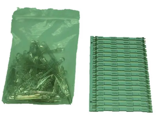
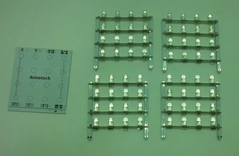
Start with the LEDs and PCB that they mount on. It helps to not break the boards apart until the LEDs are soldered, as the sprue provides some stability. As noted above, the flat of the LED lines up with the line on the board, and the square pads on the board should be on the opposite side to the LED body.

Mount the LEDs in place, and carefully solder with a fine-tipped iron. It is best to check this now, as some of the solder joins will be inaccessible when the cube is complete.

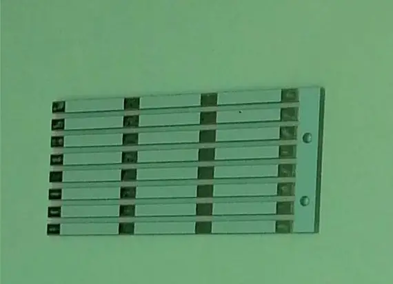
There are 64 LEDs with 4 solder joins each, so this will take a while. Carefully snap off each strip from the panel on the right when the soldering is complete.
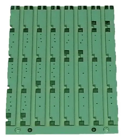
Next, take the PCBs marked A-H, and break them off their carrier.
Take four LED PCBs and place them in the slots in PCB ‘A’ and PCB ‘B’, and solder one pad on each side to keep the assembly together. Note that the ‘B’ PCB is closest to the flat line on the LED PCB, and the letters on the PCBs face opposite directions. Try to get the assembly as square as possible,
and avoid flexing it.

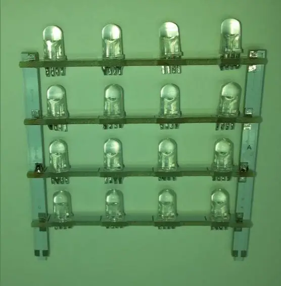
Complete C and D, E and F, and G and H in a similar fashion noting that D, F, and H will be closest to the flat line.
You should have the following:
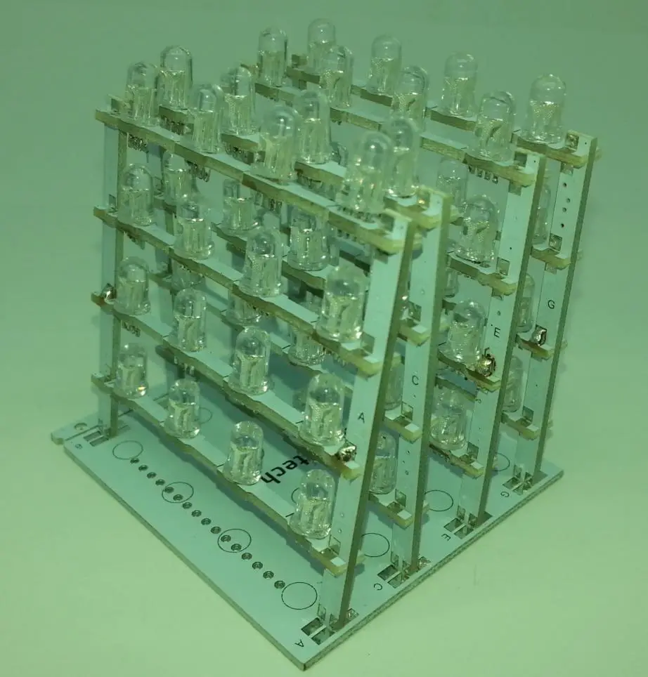
Gently slot the uprights into the ‘duinotech’ board, and try to line everything up. The letters on the vertical;
It is now easiest to turn the whole assembly upside-down and attach the last remaining pieces:
These sit on their edges across the other PCBs with their silver pads lining up with the silver pads on the underside of the LED PCBs. Thus there are four solder joins on each of these eight PCBs where they cross the other PCBs. You might need to carefully adjust the positions to get everything lined up and square. If a solder joint is preventing everything from lining up, gently apply pressure while applying heat from a soldering iron. This should allow it to move.
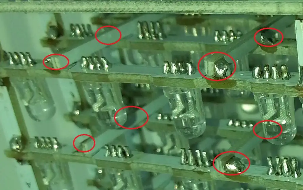
The next step is to go through and solder any other pads which need to be soldered (see circles below). You might find some locations where there is only a pad on one half of the join- there is no need to solder these (marked with crosses). Note also the four joins at the base of each tower.
The final step is to solder the headers in place. This is easiest if the headers are placed into an XC4498 driver board, and then use this as a jig to keep the pins square.
The assembly is now complete. The XC4498 is preprogrammed with a sequence of patterns, so simply powering the XC4498 should be enough to test the display. If the display doesn’t appear to be right, try rotating the Cube Module 180 degrees and reinserting it into the XC4498.