![]()
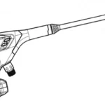
KO-7504GF Voltage and GFCI Outlet Tester
Instruction Manual
ITEM#0909981
VOLTAGE & GFCI OUTLET TESTER
MODEL#KO-7504GFI|
KOBALT and logo designs are trademarks or registered trademarks of LF, LLC. All rights reserved.
ATTACH YOUR RECEIPT HERE
Serial Number………………………
Purchase Date……………………….
Please read and understand this entire manual before attempting to assemble, operate or install the product. · Double Insulation: The tester is protected
throughout by double insulation or reinforced insulation.
![]() WARNING
WARNING
- Use extreme caution when checking electrical circuits to avoid injury due to electric shock.
- The manufacturer assumes basic knowledge of electricity on the part of the user and is not responsible for any injury or damages due to improper use of this tester.
- This product does not sense DC voltage or potentially hazardous voltages below 50 volts.
- To assure the unit is operating, always test on a known live circuit before use.
- This tester will not detect voltages in wires that are electrically shielded by metal conduit or grounded electrical enclosures.
CAUTION
- OBSERVE AND FOLLOW all standard industry safety rules and electrical codes. When necessary call a qualified electrician to troubleshoot and repair the defective electrical circuit.
![]() Questions, problems, missing parts? Before returning to your retailer, call our customer service department at 1-888-3KOBALT (1-888-356-2258), 8 a.m – 8 p.m., EST, Monday – Sunday. You could also contact us at [email protected] or visit www.lowespartsplus.com.
Questions, problems, missing parts? Before returning to your retailer, call our customer service department at 1-888-3KOBALT (1-888-356-2258), 8 a.m – 8 p.m., EST, Monday – Sunday. You could also contact us at [email protected] or visit www.lowespartsplus.com.
PRODUCT SPECIFICATIONS
| Operating Range | 115 – 125 VAC, 50-60 Hz |
| Operating Range (NCV Detection) | 50 – 600 VAC, 50-60 Hz |
| Certifications and Compliance | Conforms to UL 1436 (Circuit Tester) UL 61010-1 & 61010-2-030 (NCV Detection), CE, CAT III 1000V |
| Indicators | Visual Only (circuit tester), Audible and visual (Non-contact voltage detection) |
| Battery | One LR44 |
| Operating Environment | 32° – 104° F (0 – 40° C) 80% RH max., 50% RH above 30° C, Altitude up to 2000 meters, Indoor use, Pollution degree 2, Accordance with IED-664. |
| Cleaning | Remove grease and grime with a clean, dry cloth. |
OPERATING INSTRUCTIONS
Outlet Circuit Tester Operation:
- Plug the tester into any 120 Volt standard or GFCI outlet.
- Only a single LED should illuminate
- The text adjacent to the lit LED will indicate the wiring condition.
- If no LED illuminates then the hot is open
- If the tester indicates a wiring problem then turn off all power to the outlet and repair wiring.
- Restore power to the outlet and repeat steps.
NOTICE:
- All appliances or equipment on the circuit being tested should be unplugged to help avoid erroneous readings.
- Not a comprehensive diagnostic instrument but a simple instrument to detect nearly all probable common improper wiring conditions.
- Refer all indicated problems to a qualified electrician
- Will not detect two hot wires in a circuit.
- Will not detect a combination of defects.
- Will not indicate a reversal of grounded and grounding conductors.
TO TEST GFCI PROTECTED OUTLETS:
- To test GFCI (Ground Fault Circuit Interrupter) protected circuits plug tester into GFCI protected outlet. Verify the power is on and that the outlet is wired properly.
- Press the GFCI test button.
- If the circuit is wired properly the main GFCI outlet should trip and power to the circuit will be cut off (this is indicated by the LED lights on the tester going off).
NOTICE:
- Consult the GFCI manufacturer’s installation instructions to determine that the GFCI is installed in accordance with the manufacturer’s specifications.
- Check for correct wiring of the receptacle and all remotely connected receptacles on the branch circuit
- Operate the test button on the GFCI installed in the circuit. The GFCI must trip. If it does not — do not use the circuit — consult an electrician. If the GFCI does trip, reset the GFCI. Then, insert the GFCI tester into the receptacle to be tested.
- Activate the test button on the GFCI tester for a minimum of 6 seconds when testing the GFCI condition. Visible indication on the GFCI tester must cease when tripped.
- If the tester fails to trip the GFCI, it suggests:
a.) a wiring problem with a totally operable GFCI or
b.) proper wiring with a faulty GFCI. Consult with an electrician to check the condition of the wiring and GFCI.
Non-Contact Voltage Detection Operation:
- Before use test the battery by pressing the yellow button at the NVC detection end. The LED will flash and the speaker will chirp momentarily if the battery is good. If the indicators do not function or the chirp continually cycles, then replace the battery.
- To test for voltage press and hold the yellow button at the NVC detection end. Place the probe tip on or near the wire, device or circuit to be tested. If AC voltage greater than 50 VAC is present the LED will flash and the speaker will chirp continuously.
NOTICE:
- Static Electricity The tester is subject to electrical static interference. If the LED or tone activates momentarily it is detecting static electricity. When detecting voltage the LED and tone will cycle continuously.
- NCV detection antennae interference The presence of objects near the probe tip can decrease the sensitivity of the tester. Keep your finger away from the LED lens and probe tip to ensure adequate detection range.
Caution: GFCIs are sometimes installed in 2- wire systems (no ground wire available). This may or may not meet the local code. This tester will not trip GFCI outlets installed without a ground wire. On two-wire systems use the test and reset buttons on the GFCI outlet to demonstrate proper operation. To detect which downstream outlets are protected by the GFCI place the tester in these outlets and use the test and reset buttons. Watch for the LEDs on the tester to turn off, this will indicate proper operation.
BATTERY INSTRUCTIONS
The product comes complete with one LR44 BATTERY in the package. To Install or Replace:
- Orient the tester backside up, locate the battery compartment marked with the battery symbol secured with a screw.
- Once the battery compartment is located, use a small Phillips head screwdriver to remove the screw & release the battery cover.
- Remove the LR44 battery using caution to prevent damage or injury to the internal components.
- Place battery into tester as shown on the battery cover (Positive terminal facing toward the NCV end of the product).
- Replace battery cover and screw.
- Test on known live circuits to verify tester functionality.
WARRANTY
1-Year Limited Warranty Questions, problems, missing parts?
Before returning to your retailer, call our customer service department at 1-888-3
KOBALT (1-888-356-2258), 8 a.m. – 8 p.m., EST, Monday – Sunday.
You could also contact us at [email protected]
visit www.lowespartsplus.com.