LINKSYS 800WS Flash Unit

GENERAL SAFETY INFORMATION
Paul C. Buff Flash Units are designed for professional photography use. As with all electronic equipment,
users must observe all warnings and safety precautions. Carefully read all operating instructions and safety instructions before use.
WARNING! HIGH VOLTAGE! Flash units contain internal components that can store dangerously high voltages, even when the units are unplugged. Batteries should not be exposed to excessive heat (i.e. direct sunlight, open flame, etc.)
GENERAL PRECAUTIONS
- Do not operate a flash unit on or around flammable materials.
- Keep the unit away from fire, flames, and heated surfaces.
- Do not insert any foreign objects into any ventilation holes. Do not carry or store a flash unit together with necklaces, hair pins, nails, paper clips, or any other small metal objects.
- Do not cover the unit during operation. Air circulation must be permitted. Do not obstruct ventilation holes by covering the unit while in use or by operating from inside a carrying bag.
- Do not operate or store a flash unit in or around water. High voltage equipment can cause electric shock when operated in or near water. Your flash unit should only be used in dry, moderate conditions where the equipment is protected from rain, dirt, sand and dust.
- Do not use ungrounded power cords, power outlets or power strips. Paul C. Buff, Inc. Flash Units may only be connected to 3-wire grounded AC outlets to avoid shock hazard. Do not connect the unit to an ungrounded outlet or to a two-wire extension cord or adapter that eliminates the ground prong. Do not use any cords that have been damaged.
Paul C. Buff, Inc. flash units contain no user-serviceable parts.
Never open, disassemble, or attempt to repair any components. Only qualified technicians should service the system as incorrect disassembly can create an electric shock hazard. Fingers and other foreign objects must never be inserted or dropped inside any of the vents. If the unit has been dropped or damaged, discontinue use and contact customer service. Do not attempt to make any changes or modifications as any modifications made, outside of those performed or approved by Paul C. Buff, Inc., may present hazardous conditions and void the warranty. The only user-replaceable components are the flashtube, cover, and stand mount.
NOTE – RADIO FREQUENCY ENERGY
The LINK 800WS Flash Unit features a built-in CyberSync transceiver. This unit makes use of the radio spectrum and emits radio frequency energy. Interference can be a factor, as the frequency used is shared with other users and electronics. Please adhere to local regulations when using this device.
WHAT’S INCLUDED:
(1) LINK Flash Unit
(1) AC Power Cord
(1) Gel Diffusion Dome
(1) 14mm Flash Tube
(1) Shipping Cover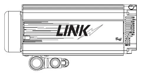
ADDITIONAL ITEMS AVAILABLE:
LINK Battery | LINK Battery Charger | HUB Remote | Color Gel Diffusion Domes
GETTING STARTED
STAND MOUNT
The stand mount is made of aluminum and features a locking handle, and two knobs. The smaller knob is what attaches the stand mount to the stud of your light stand. The larger knob connects directly to the locking handle and allows you to control and secure the tilt position of the flash unit.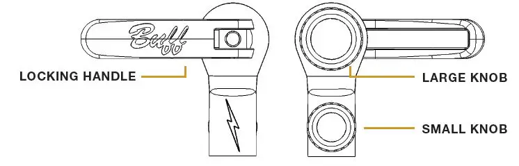
PLACING THE LINK ON A LIGHT STAND
The unit arrives with the stand mount tucked under the unit. To release, open the locking handle by pulling out and loosening the large knob by turning counter-clockwise. The stand mount will then move freely. Place the open collar at the base of the stand mount over the stud mount on your light stand. Tighten the small knob, by turning clockwise, to secure. Tighten the large knob, by turning clockwise, while holding the locking handle with your flash unit at your desired angle. Once satisfied with its placement, push the locking handle in towards the stud mount to secure. To readjust the tilt, simply pull the handle outwards from the stand mount, reposition your flash unit, and then push the locking handle in towards the stud mount to secure the placement. Make sure that the unit is secure prior to releasing.
SHIPPING COVER
The shipping cover is made of aluminum and provides protection to the flash tube when transporting or storing your flash unit. You MUST remove the shipping cover prior to turning on the flash unit.
REMOVE THE SHIPPING COVER
To remove the shipping cover, slide either of the quick-release levers to retract the four faceplate fingers holding the cover.
FRONT VIEW
ATTACHING MODIFIERS
QUICK-RELEASE LEVER and HOLDING FINGERS
The LINK faceplate utilizes a Balcar mount that has four holding fingers, controlled levers. These holding fingers expand and retract to hold various reflectors as well attachment. The LINK is compatible with all Paul C. Buff, Inc. modifiers.
UMBRELLA CHANNEL
Located above the faceplate, the umbrella channel is outfitted with internal tension clips to hold an umbrella or PLM in place without any slipping or drooping. The umbrella channel can fit up to a 9mm rod.
MAGNETIC ATTACHMENT
New to the Paul C. Buff, Inc. line of flash units is a magnetic attachment connection for difussion included with the unit), creative color, and color correcting silicone domes (both sold separately).
POWERING YOUR UNIT
AC INPUT
The AC input is located at the bottom of the unit. The LINK flash unit offers global plug-and-play with automatic power switching that allows the unit to operate on power lines from 95 to 265 VAC, 50 or 60 Hz, automatically sensing the voltage / frequency and adjusting accordingly with no user attention required. For use in North America, the unit arrives with a 15-foot power cord that has a standard IEC connector on one end and a grounded, three-pronged male plug on the other. This power cord connects to the flash unit on its back control panel and is then plugged into a suitable 120 Vac, 50-60 Hz grounded power outlet.
BATTERY
The LINK can be powered using a proprietary battery. For more information see page 9.
BACK PANEL DISPLAY
POWERING THE UNIT ON / OFF
Press and hold the POWER button for two seconds. When the LINK is powered off, the current settings are stored and will apply when the flash unit is powered on again. *To reset the LINK to factory settings, PRESS AND HOLD the POWER and TEST buttons simultaneously for 10 seconds.
DEFAULT SETTINGS
The LINK flash unit will default to the following settings:
FLASH: – COLOR MODE at -4.0
MODEL: – TRACK MODE at -4.0
SYNC MODE: – REMOTE
FREQUENCY (FREQ): – 1
CHAN: – 1
READY INDICATOR: – Visual and Audio
*When operating off battery power, the MODEL MODE will ALWAYS default to OFF. The segment that is blinking is the current segment that you are in. For general usage, and optimal light output efficiency, it is recommended to use the LINK at your camera’s max sync speed or lower.
NAVIGATING THE BACK PANEL
The unit DEFAULTS to FLASH MODE. You can quickly short press on the rotary dial to switch between FLASH and MODEL segments, for easy power adjustment. When in FLASH or MODEL SEGMENT, simply turn the rotary dial clockwise to increase the power, and turn the rotary dial counter clockwise to decrease the power.
PRESS AND HOLD the rotary dial to enter the selection menu. The segment that you are in will blink.
ROTATE THE DIAL to navigate between the available options in each segment. (i.e. choosing between ACTION, COLOR, HSS, and OFF in FLASH MODE) or to increase/decrease the power for the flash or modeling light, respectively.
SHORT PRESS in on the rotary dial to confirm your selection AND to move to the next segment.
EXIT THE SEGMENT you are in and return to the FLASH segment, by pressing and holding the rotary dial for 2 seconds.
IF NO ACTION IS MADE, the unit will revert to the FLASH segment after 10 seconds and will keep whatever setting is highlighted at time out.
FLASH MODES
COLOR MODE
In Color Mode, the LINK maintains color consistency to +/- 150°K throughout the entire power range. Color mode is also the factory default and is best for creating standard portraits.
ACTION MODE
In Action Mode, the unit’s flash duration gets shorter as power is reduced. Flash duration is basically a measurement of the burn off time of the flash once it is fired. The shorter the flash duration, the crisper your action shots in studio will be. Action mode is best utilized when stopping action (water splashes, dancer’s jumping, etc.) when you are in an environment where you have full control over your ambient light.
HSS MODE
High speed sync (HSS) mode is different from Action Mode in that it allows you to exceed your camera’s max sync speed with studio flash. The LINK can sync up to 1/8000s with compatible cameras. HSS MODE is necessary when you wish to exceed your camera’s sync speed. In HSS MODE the flash will pulse throughout the duration of the image being taken so that the full frame is exposed properly and no banding will occur. HSS is used primarily in outdoor situations where you are looking to capture movement,
or achieve a very shallow depth of field, and the ambient light is unable to be controlled.
TTL MODE
TTL Mode allows for automatic brightness adjustment for subjects who move rapidly towards and away from the flash unit, or in situations where the conditions are rapidly changing.
OFF The flash modes can all be turned off if you want to only use the modeling light.
MODEL MODES
FULL
The modeling light stays at FULL POWER regardless of the flash output.
TRACK
The modeling light tracks the flashpower output, brightening or dimming automatically as the flashpower is adjusted up or down.
ADJUST (ADJ)
The modeling light output can be adjusted independently from the flash output.
OFF
The model modes can all be turned off if you are wanting to only use the modeling light.
MODELING LIGHT FOR VIDEO USE
Offering an 800W equivalent LED, the LINK pairs a brighter light with a quiet fan, for those doing video work. Color correction domes are available (separately) in both FULL and HALF CTO.
SYNC MODES
SLAVE
The slave eye is on, causing the LINK unit to flash simultaneously whenever it “sees” the flash from another unit (still active whether or not the sync jack is in use).
REMOTE
This setting activates the internal CyberSync Transceiver. Additionally, you can set the LINK to REMOTE when utilizing the CSXCV and PocketWizard MC2 port at the top of the unit.
When using a PocketWizard MC2 the FREQ and CHAN segments will be empty. To make adjustments to the ZONE, CONTROL, and CHANNEL segments for the PocketWizard, complete the following steps:
PRESS AND HOLD the rotary dial to enter the selection menu. The segment that you are in will blink.
SHORT PRESS in on the rotary dial to confirm your selection AND to move to the next segment. Following the SYNC segment, the LINK will then provide the appropriate PocketWizard fields beginning with “2on” for ZONE, followed by “ctl” for CONTROL, and lastly “ch” for CHANNEL.
ROTATE THE DIAL to navigate between the available options in each segment.
SHORT PRESS in on the rotary dial to confirm your selection AND to move to the next segment.
SLAVE / REMOTE Both SLAVE and REMOTE are activated.
NONE
Set to NONE when plugging into the SYNC JACK for firing the unit.
FREQUENCY
The frequency (FREQ) ranges from 1 – 16. Each flash unit in your setup should all be set to the same frequency, so that they all fire together.
CHANNEL
The channel (CHAN) ranges from 1 – 16. Each flash unit in your setup should be set to its own individual channel so that it can be controlled independently from each light in your setup. The CHAN is only necessary when using the CyberSync remote system (i.e. CyberCommander, CyberSense, or BUFF App).
RECYCLE / READY INDICATOR
Recycle indication is provided by an audible beep and by the modeling lamp dimming during recycle, then restoring brightness when recycle is complete. These can be set to be used separately or in conjunction with one another. It can also be set to OFF if no indication is desired.
BATTERY INDICATOR
The BATTERY segment is not accessible via the rotary dial and is only used to visually indicate battery life. This segment will be EMPTY when no battery is connected.
LINK BATTERY
INSTALLING THE BATTERY
The battery, sold separately, slides into the channel on the underside of the unit, covering the AC input, and locking into place.
BATTERY LIFE INDICATOR
The battery life is indicated by the small lights on the rear of the battery and are illuminated when the button is pushed.
A fully charged battery will provide approximately 250 full power flashes before needing to be recharged. The LED modeling light of the LINK can be powered via the battery however, be aware if running at full power the battery will last about 45 min. (assuming no flash use during this time).
REMOVING THE BATTERY
The battery can be removed from the LINK by pressing down on the tab and sliding out from the channel. It is recommended to remove the battery prior to transporting or storing the LINK.
EXPECTED LIFETIME
The battery should last between 2 – 3 years under normal use.
MAINTAINING THE BATTERY
If you aren’t going to use the battery for an extended period of time (>3 months) it is best to leave the batteries partially discharged (40-60% of full charge) rather than fully charged.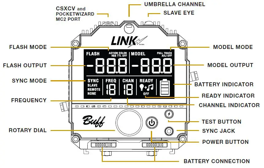 CHARGING THE BATTERY
The battery charger, sold separately, can charge up to two LINK batteries consecutively. The charger has indicator lights notifying what charging state the battery is in. When two batteries are charging, one will charge fully, and then the second will begin to charge. It takes approximately 90 min. for a depleted battery to be charged to full.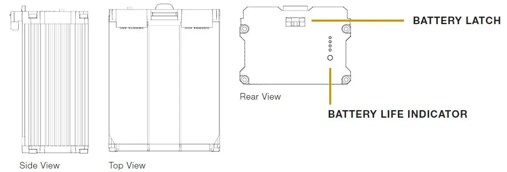
HUB REMOTE
The HUB remote (sold separately) is a new addition to our CyberSync remote system. It provides all of the necessary communication between the camera and the LINK to trigger the flash unit. While it is camera specific for usage of TTL and HSS, the HUB will function as a standard trigger similar to our CyberSync Trigger Transmitter and can be used with any camera brand. 
ATTACHING THE HUB TO YOUR CAMERA
Slide the bottom of the HUB onto your camera’s hot shoe. Turn the locking wheel clockwise to lock the HUB on to your camera.
POWERING THE HUB ON / OFF
Press and hold the POWER button, located on the right side of the HUB, for two seconds.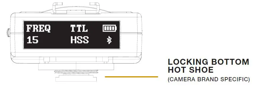
REAR DISPLAY

BLUETOOTH
By default, BLUETOOTH is ON when the HUB is first activated. To turn BLUETOOTH ON or OFF, turn the ROTARY WHEEL until BLUETOOTH appears on the display. Press in on the ROTARY WHEEL to enter the BLUETOOTH section. Turn the ROTARY WHEEL to toggle between ON and OFF. Press in on the ROTARY WHEEL to confirm your selection.
SETTING THE FREQUENCY
The FREQUENCY ranges from 1 – 16. To set the frequency turn the ROTARY WHEEL until FREQUENCY appears on the display. Press in on the ROTARY WHEEL to enter the FREQUENCY section. Turn the ROTARY WHEEL until your desired frequency appears. Press in on the ROTARY WHEEL to confirm your selection.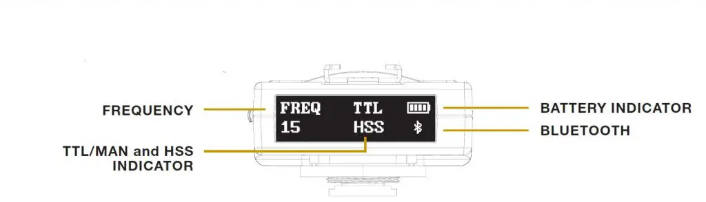
SENDING A TEST FIRE
Press in on the rotary wheel, located on the left side of the HUB. This will send a test fire to any flash units that are on the same frequency.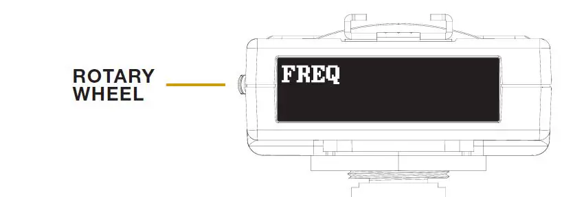
TTL MODE
To set the HUB into TTL mode, turn the ROTARY WHEEL until TTL appears on the display. Press in on the ROTARY WHEEL to enter the TTL section. Turn the ROTARY WHEEL to toggle between TTL and MAN (for manual). Press in on the ROTARY WHEEL to confirm your selection.
HSS MODE
The HUB will enter HSS mode automatically when your camera is set above it’s max sync speed. The HUB will also superseed any settings found on the LINK. For example, if the LINK is set to COLOR MODE but you are now shooting above your camera’s max sync speed, the HUB will then adjust the LINK and place it into HSS MODE.
CHANGING THE DISPLAY BRIGHTNESS
Using the ROTARY WHEEL, scroll three times so that BRIGHTNESS appears on the display. Then, press in on the ROTARY WHEEL. To adjust the brightness scroll using the ROTARY WHEEL until you have reached your desired brightness level. Press in on the ROTARY WHEEL to safe your setting. 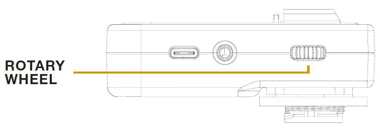 CHARGING THE HUB
To charge the HUB plug the USB-C side of the included charging cable directly into the HUB. Then plug the USB-A side into a wall outlet connector.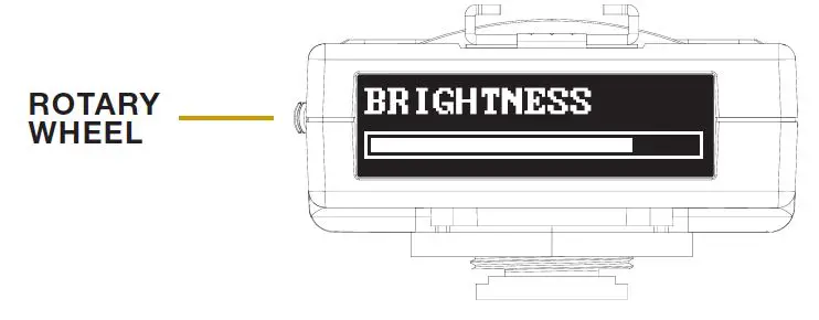
GENERAL INFORMATION
| Watt seconds | 800 Ws |
| Action Mode – Power Variability | 9 f-stops (full to 1/256 power) |
| Color Mode – Power Variability | 9 f-stops (full to 1/256 power) |
| HSS Mode – Power Variability | 9 f-stops (full to 1/256 power) |
| Recycle to Full | 3.5 sec. |
| Flash Duration (t.5) – in Action Mode | 1/1,400 sec. (at full power) | 1/42,000 sec. (at min. power) |
| Flash Duration (t.1) – in Action Mode | 1/470 sec. (at full power) | 1/18,600 sec. (at minimum power) |
| Flash Duration (t.5) – in Color Mode | 1/1,400 sec. (at full power) | 1/8,200 sec. (at minimum power) |
| Flash Duration (t.1) – in Color Mode | 1/430 sec. (at full power) | 1/5,500 sec. (at minimum power) |
| Power Requirements | Input Power: 95 – 265VAC, 50/60Hz |
| Average Current Draw | 4.5 amps |
| Internal Receiver Range (from rear of unit) | Front: 175’ | Right: 290’ | Left: 325’ | Rear: 310’ |
| Sync / Trigger Voltage | Less than 5 volts (safe for use with DSLR cameras) |
| Modeling Lamp | 800 W Equivalent Daylight-Balanced |
| Modeling Lamp Fan Audibility | 35dBA (650w equivalent) |
| LUX at 6’ with bare bulb | 320lx |
| LUX at 6’ with diffusion dome | 230lx |
| LUX at 6’ with diffusion dome and 8.5HOR | 600lx |
| LUX at 3’ with bare bulb | 1280lx |
| LUX at 3’ with diffusion dome | 920lx |
| LUX at 3’ with diffusion dome and 8.5HOR | 2400lx |
| Flashtube | 14mm single-ring flashtube (daylight-balanced and UV-coated) |
| LCD Display | 3.5” display |
| Stand Mount | Fits stands up to 5/8 in. |
| Umbrella Mount | Accepts umbrella rods up to 9mm |
| Weight | 7 lbs. 8 oz. |
| Weight with Battery | 8 lbs. 11 oz. |
| Dimensions | 6.5 in. (height) x 4.875 in. (diameter) x 12.625 in. (length) |
BUFF APP
The ‘BUFF App’ is available for both iOS and Android users. The app works in conjunction with the HUB remote and allows a user to control their lighting setup directly from their phone. Adjust the flash and model output, turn lights on and off in your setup, and more! The app also processes all firmware updates for the LINK, when they are available. Additional features to be added in future versions.
FREQUENTLY ASKED QUESTIONS
GENERAL QUESTIONS
Does the placement of the battery cause an issue with too much weight being on the back?
If the handle on the light stand is not stiff enough, the LINK will lean backwards under the weight of the battery, or fowards under the weight of a modifier (softbox, octabox, umbrella). To remedy this, simply pull out the handle of the light stand to loosen it, turn the large knob clockwise to tighten the final retention force and then pull in the handle of the light stand to re-tighten it.
What is the usable HSS range?
9 stops (full to 1/256 power)
MODELING LIGHT
Is the LED single source? Yes.
What is the CRI measurement? 90
What is the TLCI measurement? 93
What is the lumen measurement? 12,000
What is the actual wattage of the LED?
Running on AC: 95W | Running on battery: 85W
This does not affect the brightness, and is simply more efficient on battery power.
What is the LUX measurement?
Lux is not a measurement of the output of a light source. Lux describes how much light is shining on a surface. It is dependent on three things:
- The amount of light emitted by a source.
- The distance between the light source and the measurement surface.
- The surface area of the measurement surface It is highly context dependent and cannot be specified up-front.
VIDEO USE | LED Modeling Light and Fan Information
What is the decibel measurement of the fan with the LED modeling light at full power? 35dBA
What is the watt equivalent of the LED modeling light at full power?
The LED modeling light at full power emits the equivalent amount of light as a 600W Halogen bulb or a 800W Incandescent bulb.
BATTERY
How long will the battery last with the modeling light at full power (no flash)?
Approx. 60 minutes How many full power flashes on a fully charged battery (without the LED on)?
250
What is the expected lifetime of the battery before needing to be replaced?
2-3 years
Does the charger charge the two batteries consecutively or at the same time?
Consecutively
How long does it take for one battery to fully charge from depletion?
90 minutes
Will the LINK work with the Vagabond Mini?
No. The LINK draws more power than the Vagabond Mini is capable of supplying.
Will the LINK work with the Vagabond Extreme or the Vagabond 2?
Yes. The maximum output of the inverter must be 400W or greater. Pure sine wave is preferred but modified sine wave will also work. ABSOLUTELY DO NOT USE A SQUARE WAVE INVERTER!
Are there any best practices for storing and/or maintaining the life of the battery?
- Avoid over-discharging the battery (i.e. using the battery until the LINK shuts down, wait a few minutes for the battery to recover a bit and then continuing to use the battery until every last Joule is extracted). Repeated complete discharges can cause induce errors in the BMS circuitry that will prevent the battery from fully recharging.
- If you aren’t going to use the battery for an extended period of time (>3 months) it is best to leave the batteries partially discharged (40-60% of full charge) rather than fully charged. When a Lithium-Ion battery is fully charged, it will oxidize much faster, which reduces its useful life.
**The LINK battery (purchased separately) arrives with a 1-Year Factory Warranty.**
WARRANTY INFORMATION
The LINK 800WS flash unit arrives with our 60-Day Absolute Satisfaction Guarantee. If you are not satisfied with the system for any reason, you may return it within 60 days for a complete refund, minus the cost of shipping. In order to receive your full refund, ensure that all items originally arriving with the system are included in your return.
The unit also arrives with our 2-Year Factory Warranty. Paul C. Buff, Inc. guarantees to the original purchaser an individual product factory warranty against manufacturer defects in materials and workmanship, beginning with the date that the product is originally shipped to the customer.
Terms and Conditions of Warranty:
- This warranty is limited to the repair or replacement of a product or component that should become defective under normal use, as outlined in the product description and product manual.
- If, during the applicable warranty period, the product is found to be defective by Paul C. Buff, Inc., we will repair or replace the defective component without charge for labor or parts.
- This warranty will not cover deterioration or malfunction resulting from accident, act of nature, abuse, misuse, neglect, unauthorized product repair, shipping of the product, opening of or modification or failure to follow instructions supplied with product.
- This warranty does not apply to any flashtubes, modeling lamps, or batteries, that may arrive with a product as these become exhausted based on normal use.
- The product must be returned to Paul C. Buff, Inc. for warranty service. For customers in the United States, warranty service includes return shipment via FedEx. Customers outside of the United States will be responsible for all shipping fees, duties, taxes and brokerage fees to ship the product to and from our offices.
- Paul C. Buff, Inc. IS NOT RESPONSIBLE FOR ANY SPECIAL, INCIDENTAL, INDIRECT, PUNITIVE OR CONSEQUENTIAL DAMAGES, LOST PROFITS, OR PRODUCTS LOST, STOLEN OR DAMAGED DURING SHIPPING, WHETHER ARISING IN CONTRACT, TORT (INCLUDING NEGLIGENCE), OR OTHERWISE. ALL LIABILITY OF Paul C. Buff, Inc. SHALL BE LIMITED TO THE REPAIR OR REPLACEMENT, AT OUR OPTION, OF ANY DEFECTIVE PRODUCT.
If you have questions about the guarantee or warranty, please contact our customer service team via phone at 1.800.443.5542 or 615.383.3982. We are available Monday through Friday, from 9:00 am to 5:00 pm, CT. You may also email our customer service team at [email protected].
For more information on our products and the various accessories that are compatible with the LINK 800WS flash unit, visit our website at www.paulcbuff.com.
FCC INFORMATION
NOTE: This equipment has been tested and found to comply with the limits for a Class B digital device, pursuant to part 15 of the FCC Rules. These limits are designed to provide reasonable protection against harmful interference in a residential installation. This equipment generates, uses and can radiate radio frequency energy and, if not installed and used in accordance with the instructions, may cause harmful interference to radio communications. However, there is no guarantee that interference will not occur in a particular installation.
If this equipment does cause harmful interference to radio or television reception, which can be determined by turning the equipment
off and on, the user is encouraged to try to correct the interference by one or more of the following measures:
- Reorient or relocate the receiving antenna.
- Increase the separation between the equipment and receiver.
- Connect the equipment into an outlet on a circuit different from that to which the receiver is connected.
- Consult the dealer or an experienced radio/TV technician for help.
Warning: Changes or modifications to this unit not expressly approved by the part responsible for compliance could void the user’s authority to operate the equipment.
FCC Radiation Exposure Statement
The device has been evaluated to meet general RF exposure requirement. The device can be used in fixed/mobile (min 20cm) exposure condition without restriction.
This device complies with part 15 of the FCC Rules. Operation is subject to the following two conditions:
- This device may not cause harmful interference, and
- this device must accept any interference received, including interference that may cause undesired operation.