
Wireless Security Camera

CAUTION: TO REDUCE THE RICK OF ELECTRIC SHOCK DO NOT REMOVE COVER. NO USER SERVICABLE PARTS INSIDE. REFER SERVICING TO QUALIFIED SERVICE PERSONNEL.
WARNING: TO PREVENT FIRE OR SHOCK HAZARD, DO NOT EXPOSE THIS UNIT TO RAIN OR MOISTURE.
Important Safeguards
In addition to the careful attention devoted to quality standards in the manufacture process of your product, safety is a major factor in the design of every instrument. However, safety is your responsibility too. This sheet lists important information that will help to ensure your enjoyment and proper use of the product and accessory equipment. Please read them carefully before operating and using your product.
General Precautions
- All warnings and instructions in this manual should be followed.
- Do not use receivers or video monitors in humid or wet places.
- Keep enough space around the product for ventilation. Slots and openings in the storage cabinet should not be blocked.
- It is highly recommended to connect the product to a surge protector to protect from damage caused by electrical surges. It is also recommended to connect the product to an uninterruptible power supply (UPS), which has an internal battery that will keep the product running in the event of a power outage.
- Remove the plug from the outlet before cleaning. Do not use liquid aerosol detergents. Use a water dampened cloth for cleaning.
Installation
- Read and Follow Instructions – All the safety and operating instructions should be read before the product is operated. Follow all operating instructions.
- Retain Instructions – The safety and operating instructions should be retained for future reference.
- Heed Warnings – Comply with all warnings on the product and in the operating instructions.
- Polarization – Do not defeat the safety purpose of the polarized or grounding-type plug.
A polarized plug has two blades with one wider than the other.
A grounding type plug has two blades and a third grounding prong.
The wide blade or the third prong are provided for your safety.
If the provided plug does not fit into your outlet, consult an electrician for replacement of the obsolete outlet. - Power Sources – This product should be operated only from the type of power source indicated on the marking label. If you are not sure of the type of power supplied to your location, consult your video dealer or local power company. For products intended to operate from battery power, or other sources, refer to the operating instructions.
- Overloading – Do not overload wall outlets or extension cords as this can result in the risk of fire or electric shock. Overloaded AC outlets, extension cords, frayed power cords, damaged or cracked wire insulation, and broken plugs are dangerous. They may result in a shock or fire hazard. Periodically examine the cord, and if its appearance indicates damage or deteriorated insulation, have it replaced by your service technician.
- Power-Cord Protection – Power supply cords should be routed so that they are not likely to be walked on or pinched by items placed upon or against them. Pay particular attention to cords at plugs, convenience receptacles, and the point where they exit from the product.
- Surge Protectors – It is highly recommended that the video equipment be connected to a surge protector. Doing so will protect the equipment from damage caused by power surges. Surge protectors should bear the UL listing mark or CSA certification mark.
- Uninterruptible Power Supplies (UPS) – Because this product is designed for continuous, 24/7 operation, it is recommended that you connect the product to an uninterruptible power supply. An uninterruptible power supply has an internal battery that will keep the product running in the event of a power outage. Uninterruptible power supplies should bear the UL listing mark or CSA certification mark.
Caution: Maintain electrical safety. Power line operated equipment or accessories connected to this product should bear the UL listing mark or CSA certification mark on the accessory itself and should not be modified so as to defeat the safety features. This will help avoid any potential hazard from electrical shock or fire. If in doubt, contact qualified service personnel. - Ventilation – Slots and openings in the case are provided for ventilation to ensure reliable operation of the product and to protect it from overheating. These openings must not be blocked or covered. The openings should never be blocked by placing the video equipment on a bed, sofa, rug, or other similar surface. This product should never be placed near or over a radiator or heat register. This product should not be placed in a built-in installation such as a bookcase or rack unless proper ventilation is provided and the product manufacturer’s instructions have been followed.
- Attachments – Do not use attachments unless recommended by the product manufacturer as they may cause a hazard.
- Water and Moisture – Do not use receivers or video monitors near water — for example, near a bath tub, wash bowl, kitchen sink or laundry tub, in a wet basement, near a swimming pool and the like.
- Heat – The product should be situated away from heat sources such as radiators, heat registers, stoves, or other products (including amplifiers) that produce heat.
- Accessories – Do not place this video equipment on an unstable cart, stand, tripod, or table. The video equipment may fall, causing serious damage to the product. Use this product only with a cart, stand, tripod, bracket, or table recommended by the manufacturer or sold with the product. Any mounting of the product should follow the manufacturer’s instructions and use a mounting accessory recommended by the manufacturer.
- Camera Extension Cables – Check the rating of your extension cable(s) to verify compliance with your local authority regulations prior to installation.
- Mounting – The cameras provided with this system should be mounted only as instructed in this guide or the instructions that came with your cameras, using the provided mounting brackets.
- Camera Installation- Cameras are not intended for submersion in water. Not all cameras can be installed outdoors. Check your camera environmental rating to confirm if they can be installed outdoors. When installing cameras outdoors, installation in a sheltered area is required.
Service
- Servicing – Do not attempt to service this video equipment yourself, as opening or removing covers may expose you to dangerous voltage or other hazards. Refer all servicing to qualified service personnel.
- Conditions Requiring Service – Unplug this product from the wall outlet and refer servicing to qualified service personnel under the following conditions:
A. When the power supply cord or plug is damaged.
B. If liquid has been spilled or objects have fallen into the product.
C. If the product has been exposed to rain or water.
D. If the product has been dropped or the cabinet has been damaged.
E. If the product does not operate normally by following the operating instructions. Adjust only those controls that are covered by the operating instructions. Improper adjustment of other controls may result in damage and will often require extensive work by a qualified technician to restore the product to its normal operation.
F. When the product exhibits a distinct change in performance. This indicates a need for service. - Replacement Parts – When replacement parts are required, have the service technician verify that the replacements used have the same safety characteristics as the original parts. Use of replacements specified by the product manufacturer can prevent fire, electric shock, or other hazards.
- Safety Check – Upon completion of any service or repairs to this product, ask the service technician to perform safety checks recommended by the manufacturer to determine that the product is in safe operating condition.
Use
- Cleaning – Unplug the product from the wall outlet before cleaning. Do not use liquid cleaners or aerosol cleaners. Use a damp cloth for cleaning.
- Product and Cart Combination – Product and cart combination should be moved with care. Quick stops, excessive force, and uneven surfaces may cause the product and cart combination to overturn.
- Object and Liquid Entry – Never push objects of any kind into this product through openings as they may touch dangerous voltage points or “short-out” parts that could result in a fire or electric shock. Never spill liquid of any kind on the product.
- Lightning – For added protection of this product during a lightning storm, or when it is left unattended and unused for long periods of time, unplug it from the wall outlet and disconnect the antenna or cable system. This will prevent damage to the product due to lightning and power line surges.
NOTICES
FCC Notice:
This equipment has been certified and found to comply with the limits regulated by the FCC part 15, subpart C. Operation is subject to the following two conditions: (1) this device may not cause harmful interference, and (2) this device must accept any interference received, including interference that may cause undesired operation.
This equipment has been tested and found to comply with the limits for a Class B digital device, pursuant to Part 15 of the FCC rules. These limits are designed to provide reasonable protection against harmful interference in a residential installation. This equipment generates, uses and can radiate radio frequency energy and, if not installed and used in accordance with the instructions, may cause harmful interference to radio communications.
However, there is no guarantee that interference will not occur in a particular installation. If this equipment does cause harmful interference to radio or television reception (which can be determined by turning the equipment on and off), the user is encouraged to try to correct the interference by one or more of the following measures:
- Reorient or relocate the receiving antenna
- Increase the separation between the equipment and receiver
- Connect the equipment into an outlet on a circuit different from that to which the receiver is connected
- Consult the dealer or an experienced radio or television technician for assistance
Warning: To ensure compliance with the FCC’s RF exposure guidelines, this equipment should be installed and operated with minimum distance 20cm (7.87in) between the radiator and nearby persons.
Industry Canada Notice:
This device complies with Industry Canada licence-exempt RSS standard(s). Operation is subject to the following two conditions: (1)This device may not cause harmful interference, and (2) This device must accept any interference received, including interference that may cause undesirable operation.
This Class B digital apparatus complies with Canadian ICES-003.
MODIFICATION:
Any changes or modifications not expressly approved by the grantee of this device could void the user’s authority to operate the device.
RoHS:
This product is fully compliant with the European Union Restriction of the Use of Certain Hazardous Substances in Electrical and Electronic Equipment (“RoHS”) Directive (2002/95/EC). The RoHS directive prohibits the sale of electronic equipment containing certain hazardous substances such as lead, cadmium, mercury, and hexavalent chromium, PBB, and PBDE in the European Union.
It is imperative that the user follows the guidelines in this manual to avoid improper usage which may result in damage to the product, electrical shock, and fire hazard injury. In order to improve the features, functions, and quality of this product, the specifications are subject to change without notice from time to time.
Features
- Real-time (up to 30fps) wireless video with MPEG-4 compression @ 640×480 (VGA) resolution1
- Extended bandwidth delivers super smooth high frame rate video1
- SignalGuard Technology continuously monitors the wireless signal and automatically reconnects upon detecting low signal strength
- Next generation adaptive Frequency Hopping Spread Spectrum (FHSS) technology greatly reduces conflicts with competing signals
- Built-in microphone for listen-in audio2
- Built-in auto-mechanical infrared camera filter achieves accurate color reproduction in varying lighting conditions
- Night vision range up to 135ft (41m) / 90ft (27m)3
- Simple installation. No video cable required4
- Weatherproof camera and power connectors, can be installed indoors or outdoors5
- Easily connects to any surveillance DVR (BNC) or TV (RCA)
- High gain antennas provide up to 165ft (50m) indoor / 500ft (152m) outdoor wireless range6
- Vandal resistant camera design with cable pass-through mounting bracket
- At full signal strength. Limit number of obstructions to ensure best performance.
- Audio recording without consent is illegal in certain jurisdictions. Lorex Technology Inc. assumes no liability for use of its products that does not confirm with local laws.
- Stated IR illumination ranges are based on ideal conditions in typical outdoor night time ambient lighting and total darkness. Actual range and image clarity depends on installation location, viewing area and light reflection/absorption level of object.
- Camera and receiver requires a wired connection to an electrical outlet (power adapters included).
- Not intended for submersion in water. Installation in a sheltered area required.
- Maximum wireless transmission range. Actual range dependent upon building materials and other obstructions in path of wireless signal.
Getting Started
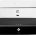
Wireless Receiver
- Removable Antenna (SMA Type): Pre-attached to the receiver
- Pairing Status LED: Glows green continuously when a camera is paired to the receiver. Flashes on and off slowly when pairing mode is active and flashes rapidly when camera is out of range.
- Pairing Button: For details, see Pairing Cameras
- DC Power: Connect power adapter to power on the receiver.
- Termination Cable: Includes BNC video output cable and RCA audio output.
- Antenna Jack

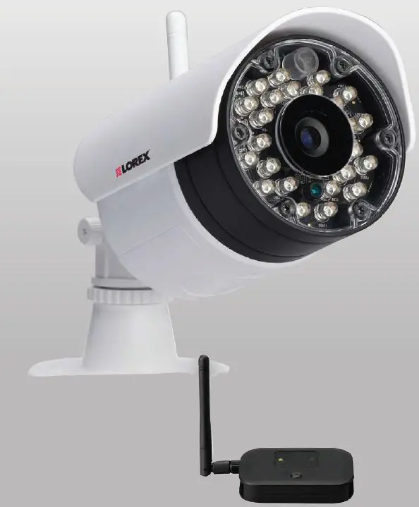
Wireless Camera
- Microphone
- Removable Antenna (SMA Type): Pre-attached to the back of camera.
- Camera Stand
- DC Power: Connect power adapter to power on the camera.
- Pairing Button: For details, see “Pairing Cameras” on page 9.
- Antenna Jack
ATTENTION – This camera includes an Auto Mechanical IR Cut Filter. When the camera changes between Day/Night viewing modes, an audible clicking noise may be heard from the camera. This clicking is normal and indicates that the camera filter is working.
Installing the Camera
Camera is suitable for outdoor installation. Installation in a sheltered location is recommended. For example, install under shelter protected from the elements, such as beneath roof eaves. The diagram to the right shows an example of an ideal location for outdoor placement.
Installation Warnings
- Aim the camera to optimize the viewing area: select a location that provides a clear view of the area you want to monitor, that is free from dust, and that is not facing a strong light source or direct sunlight.
- Avoid installing the camera where there are thick walls or obstructions between the camera and the receiver.
- Avoid installing in a location which requires the wireless signal to pass through cement, concrete, and metal structures. This will reduce the range of transmission. For details, see “Appendix B: Frequently Asked Questions” on page 11.
- Select a location for the camera that has an ambient temperature between 14°F~122°F (-10°C~50°C)
- Not intended for submersion in water. For outdoor use, installation in a sheltered location is recommended.
Mounting Positions
You may mount your camera on a wall, ceiling, or counter. See the images below for recommended configurations of the camera stand and antenna.
NOTE: For ceiling installation, position the antenna as high as the ceiling allows. See the “Ceiling” mounting position in the figure above.
Before mounting the camera permanently, carefully plan where and how the camera will be positioned and where you will route the cable that connects the camera to the power adapter. Verify the camera’s performance by observing the image on a monitor when the camera is positioned where it will be permanently installed.
To Install the Camera
- Use the included mounting screws to mount the camera to the mounting surface:
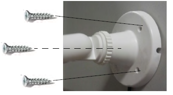
- Mark the positions of the screw holes on the mounting surface.
- Drill holes and insert the drywall plugs (included) as needed.
- Firmly attach the camera to the mounting surface using the included screws.
NOTE: If you are running the power cable through the mounting surface, connect power before firmly attaching the camera to the mounting surface.
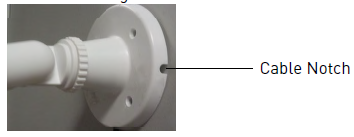
NOTE: If you are running the power cable along the mounting surface, you need to run the power connector cable through the cable notch on the camera base before firmly attaching the camera to the mounting surface.
- Mark the positions of the screw holes on the mounting surface.
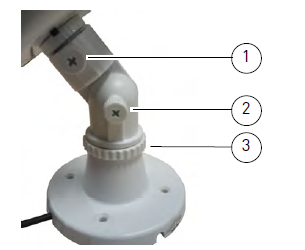
- Loosen the thumbscrews (1, 2) and the adjustment ring (3) by turning them counter clockwise.
- Adjust the angle of the camera until the desired view is set. Tighten the thumbscrews and the adjustment ring to secure the camera’s position.
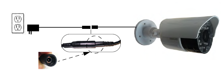
- Connect the power cable from the camera to the weatherproof power connector. Plug the power adapter into a power outlet or surge protector.
- Remove protective film from the camera lens to uncover the microphone. The protective film may prevent the microphone from working if not removed.


Connecting to a DVR
Before powering on the receiver, make sure to first connect and power on the camera. This will ensure a proper connection.
- Connect the BNC video cable from the receiver to the video input on your DVR.
- Connect the RCA audio cable from the receiver to the corresponding audio input. The audio input number or name should match the video input where you connect the BNC cable (e.g. Video Input 1 and Audio Input 1).
- Connect the power cable to the power port on the receiver and plug it into a power outlet or surge protector.
- Place the receiver where it will have clear reception to your camera1.
NOTE: If your camera is out of range, the pairing status LED will flash on and off rapidly. OPTIONAL: Use the double-sided tape to secure the receiver to a surface (e.g. wall).
Connecting to a TV

- Connect the included BNC-to-RCA adapter to the BNC connector on the receiver. Connect the other end of the BNC-to-RCA adapter to the RCA video input on your television.
- Connect the RCA audio connector from the receiver to the audio input on your television.
- Connect the power cable to the power port on the receiver and plug it into a power outlet or surge protector.
- Power on your television and select the input that the receiver is connected to.
- Place the receiver where it will have clear reception to your camera1.
Pairing Cameras
IMPORTANT: The camera and the receiver have already been paired out of the box, which means that they are exclusively communicating with each other. If for some reason the pairing is lost, follow these steps to pair the camera and receiver.
To pair the camera to the receiver:
- Make sure that the camera and receiver are both powered up and all antenn
as are properly attached. - Press and hold the PAIR button on the receiver for 5 seconds to activate pairing mode.
The pairing status LED will flash on and off slowly.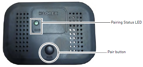
- Press the PAIR button on the back of the camera within 30 seconds of pressing the PAIR button on the receiver.
If pairing is successful, live video from the camera will appear on the monitor.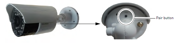


Appendix A: System Specifications
General Specifications
| TX Frequency Range | 2.400GHz~2.480GHz |
| TX Power | 16dBm |
| Unobstructed Effective Range | 165ft (50m) indoor
500ft (152m) outdoor1 |
| Data Rate | 4 Mb/s |
| Modulation | GFSK |
| Spread Spectrum | FHSS |
| Operating Temperature Range | 14°F ~ 122°F / -10°C ~ 40°C |
Maximum wireless transmission range. Actual range dependent upon building materials and other obstructions in path of wireless signal.
Receiver Specifications
| RX Sensitivity | -81dBm |
| Demodulation | GFSK |
| Supported Resolution | VGA (640×480) up to 30 frames per second |
| Termination | 1x BNC video, 1x RCA audio |
| Power Requirement | 9V DC +/- 5% |
| Power Consumption | 270mA Max |
| Dimensions (W x D x H) | 53 x 137 x 86mm / 2.1 x 5.4 x 3.4″ (with antenna attached) |
| Weight | 0.1kg / 0.3lbs |
Camera Specifications
| Image Sensor Type | 1/4″ Color CMOS Image Sensor |
| Effective Pixels | H: 640 V: 480 |
| Image Compression | MPEG4 |
| Image Resolution | VGA (640×480) |
| Lens | 3.6mm F2.0 |
| Field of View (Diagonal) | 55° |
| AGC | On |
| Power Requirement | 9V DC +/- 5% |
| Power Consumption | 430mA Max with IR LED
220mA Max without IR LED |
| Environmental Rating1 | IP66 |
| IR LED Quantity / Type | 24 pieces / 850nm |
| Night Vision Range2 | 135ft (41m) / 90ft (27m) |
| Built in Auto IR Turn On / Off | CdS Drive Auto IR LED turn On/Off Circuit |
| Dimensions (W x D x H) | 79 x 203 x 117mm / 3.1 x 8.0 x 4.6″ (with antenna and sun-
shade) |
| Weight | 0.3kg / 0.6lbs |
- Not intended for submersion in Installation in a sheltered area recommended.
- Stated IR illumination ranges are based on ideal conditions in typical outdoor night time ambient lighting and in total darkness. Actual range and image clarity depends on installation location, viewing area, and light reflection / absorption level of OBJECT.
Appendix B: Frequently Asked Questions
Wired vs. Wireless Cameras
A wired camera has a video cable that transmits the video signal from the camera to a recording or viewing device.
A wireless camera does not use a video cable. Instead, it wirelessly transmits the video signal to a wireless receiver that is connected to your DVR. Wireless cameras do not require video cabling to be run between the camera and the DVR, which reduces installation time and cost.
Does a wireless camera require power?
Yes. Wireless cameras require two power sources: one connected to the camera, and the other to the receiver. The term “wireless” refers to the lack of a video cable between the camera and the receiver.
How far can a wireless camera transmit a video signal?
In an open field (with line of sight), a typical wireless camera has a range between 250 – 500 feet. ‘Line-of-sight’ means that there are no obstructions between the camera and receiver. Obstructions include walls, buildings, trees, and certain electronic devices. Materials containing moisture (for example, leaves) may also act as an obstruction. Cubical walls, drywall, glass, and windows generally do not degrade wireless signal strength.
In a closed environment—such as the interior of a house—the wireless camera range is between 100 – 165 feet. The signal range varies depending on the type of building materials or objects the wireless signal must pass through. The signal range also depends on whether there are competing signals using the same frequency as the camera. For example, signals from cordless phones or routers may affect signal strength. Adaptive Frequency Hopping Spread Spectrum (FHSS) technology featured in the latest Lorex models greatly reduce signal interference.
Range Limiting Factors1
Signal Reduction Through Materials
Signal strength decreases as it passes through different types of material. The table below shows how signals become reduced when passing through different materials:
| Material | Signal Reduction (%) |
| Plaster & Wood | 10 – 30% |
| Brick | 30 – 50% |
| Concrete Cinder Blocks | 50 – 70% |
| Metal & Metal Cladding | 70 – 90% |
NOTE: Signals that must pass through wet or moist material (e.g. shrubs and trees) may be significantly reduced.
The stronger the signal strength, the higher the video frame rate. The lower the signal strength, the lower the video frame rate.
Are digital wireless camera signals secure?
Yes. Lorex digital wireless products feature a wireless transmission method called Frequency Hopping Spread Spectrum (FHSS). This type of signal is highly resistant to eavesdropping as it generates a channel hopping sequence using an algorithm generated by the receiver, which only the camera can follow through the “pairing” function.
Pairing is an electronic handshake between digital wireless devices. Digital wireless cameras can only be paired to one receiver. This is to prevent interception by third parties, and prevents any other device from picking up the signal—this also means that you cannot pair one camera to multiple receivers.
How many frames per second should I expect from a digital wireless camera?
Current Lorex digital wireless cameras offer 10 – 30 FPS (Frames Per Second) performance. Actual frame rate depends mainly on signal strength (see the chart in section above).
For details on supported resolutions and frame rates for this model, see “Appendix A: System Specifications” on page 10.
How many wireless cameras can I install?
It is recommended to install a maximum of 4 wireless cameras per system (4 receivers and 4 cameras). Minimum space between receivers should be 4 inches / 10cm and minimum space between cameras should be 6.5ft / 2m to minimize potential signal strength degradation.
Appendix C: Troubleshooting
If you have problems with your system, there is often a quick and simple solution. Please try the following:
| Problem | Solution |
| There is no picture from the camera(s) | • Make sure that the camera is plugged into a power outlet and that the power adapter is plugged in properly.
• Make sure receiver is plugged into a power outlet. • Move the camera closer to the receiver. • Make sure BNC video output cable is connected to your DVR or television. • If you are viewing your camera(s) using a TV, make sure you have the correct input selected. |
| There is no audio from the camera(s) | • Make sure the RCA audio output cable is connected to your DVR or television audio input.
• Make sure audio recording is enabled on your DVR. See your DVR manual for further instruction. • Make sure to remove the protective film from the camera lens. The microphone is located on the front of the camera and will not work properly if the protective film is left on. |
| The picture is dropping | • Move the camera closer to the receiver.
• Try repositioning the camera, receiver, or both to improve the reception. |
| The picture is or has become choppy | • The picture may become choppy when experiencing a lower frame rate (e.g. 6 frames per second vs. a higher 20 frames per second).
• Try moving the camera closer to the receiver. • Remove obstructions between the receiver and camera. |
| The picture is white | • “Washout” or “white wash” can occur when a strong light source is pointed at the camera lens. The camera lens is not harmed during a white wash.
• Do not point your camera towards a bright light source. |
| The picture is too dark | • If using during the day, the camera may not be getting enough light. Reconsider the position of your camera. |
| The picture is too bright | • If using during the day, the camera may be getting too much light. Reconsider the position of your camera. |
| Night vision is not working | • Night vision activates when light levels drop. The area may have too much light. |
| Bright spot in video when viewing camera at night | • Night vision reflects when pointing a camera at a window. Move the camera to a different location. |
Appendix D: Extending Wireless Signal Range
DISCLAIMER: Certain accessories are not available in all markets. There are several ways to boost your wireless signal as well as options to help you extend the range of the wireless signal.
Clear Line-of-Sight: You should always try to ensure there is a clear line-of-sight between the camera and the receiver.

Extending Your Wireless Signal
Even with a clear line-of-sight between your camera(s) and your receiver(s), you may experience a lower video frame rate simply due to the distance between your wireless devices.
Accessory antennas are available that can help extend the range of your wireless signal.
GHZ Directional Wireless Panel Antenna
Use the 2.4GHz Directional Wireless Panel Antenna
(model #: ACCANTD9) to focus a wireless signal onto the camera in order to increase the range of transmission
(clear line-of-sight between the camera and the antenna is required). A 20ft extension cable is included to help to properly position the antenna.

Scenario 1: Single Receiver Installation
Attach a directional antenna to the camera and/or the receiver. It is recommended to attach the antenna to the receiver and place it in a location that has clear line-of-sight to the camera. Ensure that the directional antenna is pointing toward the other antenna. For example, if the directional antenna is connected to your receiver, the directional antenna should point at the camera (see figure above). During the installation, check the reception on your DVR.
Scenario 2: Multiple Camera / Receiver Installation
If you are using multiple wireless cameras and receivers in your installation, attach directional antennas to the camera(s) and receiver(s) that are farthest away from each other. Follow these guidelines to increase the signal strength between your cameras and receivers:
- Point directional antennas towards the receiver for each camera.
- Keep as much space as possible between each receiver.
- Keep as much space as possible between directional antennas if using more than one.
- Minimize the amount of obstructions (e.g. walls or trees) between the antennas and receivers.
- During the installation, check the reception of each camera on your DVR.
Visit www.lorextechnology.com for more details on wireless antennas and accessories.