Lutron® Smart BridgeT
Please read before installing:
Contents supplied:
Lutron®
Smart BridgeT
(L-BDG) *
5 V- 300 mA
Power Supply
(T-5DC-USB)
5 V- 1000 mA
Ethernet Cable
Double your warranty
Love LutronR products? Have ideas for making them better? Tell us what you think and we’ll extend your warranty by 1 year. www.casetawireless.com/register
Download the Lutron® app
www.casetawireless.com/LutronApp
Lutron
Search for “Lutron Caseta” Apple is a trademark of Apple Inc., registered in the U.S. and other countries. App Store is a service mark of Apple Inc.
The Lutron® app will walk you through setup
Warranty
For warranty information, please visit 369-119_Wallbox_Warranty [pdf]
FCC/IC Information
This device complies with part 15 of the FCC Rules and Industry Canada license-exempt RSS standard(s). Operation is subject to the following two conditions: (1) This device may not cause interference, and (2) this device must accept any interference, including interference that may cause undesired operation. Modifications not expressly approved by Lutron Electronics Co., Inc. could void the user’s authority to operate this equipment.
Note: This equipment has been tested and found to comply with the limits for a Class B digital device, pursuant to part 15 of the FCC Rules. These limits are designed to provide reasonable protection against harmful interference in a residential installation. This equipment generates, uses and can radiate radio frequency energy and, if not installed and used in accordance with the instructions, may cause harmful interference to radio communications. However, there is no guarantee that interference will not occur in a particular installation. If this equipment does cause harmful interference to radio or television reception, which can be determined by turning the equipment off and on, the user is encouraged to try to correct the interference by one or more of the following measures:
- Reorient or relocate the receiving antenna.
- Increase the separation between the equipment and receiver.
- Connect the equipment into an outlet on a circuit different from that to which the receiver is connected.
- Consult the dealer or an experienced radio/TV technician for help.
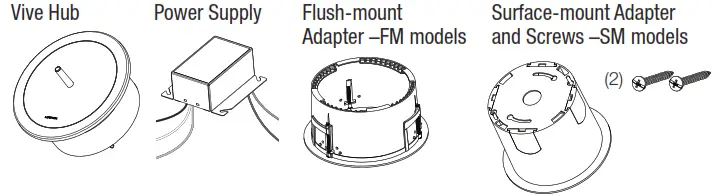
Vive Hub
Installation Instructions
Please Read Before Installing

P/N 041744
Rev B
Power Supply (PS-J-20W-UNV):
Input: 120–277 V~ 50 / 60 Hz 0.6 A
Output: 24 V- 830 mA
Vive Hub (HJS-): 24-36 V- 350 mA
| Model Numbers | Description |
| HJS-0-FM | Starter hub, flush-mount adapter and power supply |
| HJS-1-FM | Vive hub, flush-mount adapter, and power supply |
| HJS-1-SM | Vive hub, surface-mount adapter and power supply |
| HJS-2-FM | Premium Vive hub, flush-mount adapter and power supply |
| HJS-2-SM | Premium Vive hub, surface-mount adapter and power supply |
| Replacement Parts | Description |
| PS-J-20W-UNV | Vive hub external power supply |
| H-MOUNT-FM | Flush-mount installation bracket |
| H-MOUNT-SM | Surface-mount installation bracket |
Included Components
Important Notes
General
- For installation by a qualified electrician in accordance with all local and national electrical codes.
- In Canada, separate over-current protection is required to be in accordance with the Canadian
Electrical Code, Part 1. - The primary branch circuit must be protected by a 15 A or 20 A breaker (as applicable).
- The primary wiring must be 18 AWG to 14 AWG (1.0 mm2 to 2.5 mm2) and rated for at least 167 ˚F (75 ˚C).
- If moisture or condensation is evident, allow the product to dry completely before installation.
- Operate between 32 °F and 104 °F (0 °C and 40 °C).
- 0% to 90% humidity, non-condensing.
- For indoor use only.
Vive Hub
- Clean the Vive hub with a soft damp cloth only. DO NOT use any chemical cleaners.
- DO NOT paint the Vive hub.
- The Vive hub is part of a system and cannot be used to control a load without a compatible system device. Please refer to the system device(s) instruction sheet or www.lutron.com for installation information.
- Up to 700 Lutron wireless devices can be associated with the Vive hub.
- Installation near metal, other than a junction box, may reduce RF range. The Vive hub should be at least 12 in (305 mm) away from metal objects.
- All wireless devices must be within 71 ft (22 m) of the Vive hub. This range applies to both Clear Connect devices and Wi-Fi.
- A corporate Wi-Fi network can interfere with the Wi-Fi on the Vive hub. Where a corporate Wi-Fi network exists, it is recommended to connect the Vive hub to the corporate network using the Ethernet connection on the hub and disable the hub’s Wi-Fi.
- Must be mounted a minimum of 10 ft (3 m) from Wi-Fi router.
- For a secure way to de-commission the Vive hub, please contact Lutron Customer Assistance.
Typical Application
Instructions
Product Overview
(Flush-mount Adapter shown)
Installation
Turn OFF power at circuit breaker.
 WARNING! Shock Hazard. May result in serious injury or death. Turn off power at circuit breaker before installing the unit.
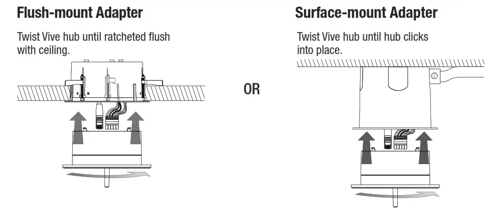
Installing the Mounting Adapter
The Vive hub can be mounted on a variety of ceiling materials (thickness ranging from 1/4 in to 11⁄4 in (6 mm to 32 mm) with the mounting bracket provided.
Flush-Mount adapter
A. Cut a 6 in (152 mm) diameter mounting hole in the ceiling to insert the mounting bracket.
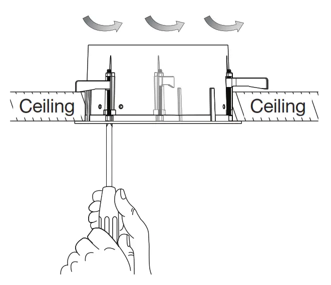
B. Insert the flush-mount Adapter into the hole and rotate the three brackets outwards by turning screws.
C. Using a Phillips head screwdriver, hand-tighten the brackets, clamping the adapter to the ceiling. DO NOT overtighten.
Surface-Mount adapter
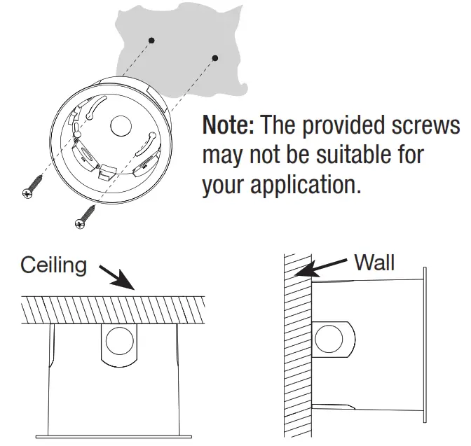
A. 1. Remove installed doors to access the optional conduit knockouts. The knockouts provide a connection point for 1/2` in or 3/4 in (13 mm or 19 mm) conduit.
2. Attach the surface-mount adapter to the wall or ceiling using the included screws or appropriate screws that will securely mount the device.
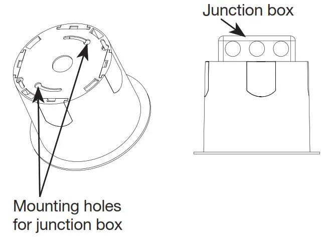
B. Alternate installation methods: Attach the surface-mount adapter to a junction box (4 in x 4 in (102 mm x 102 mm) square or 4 in(102 mm) octagonal).
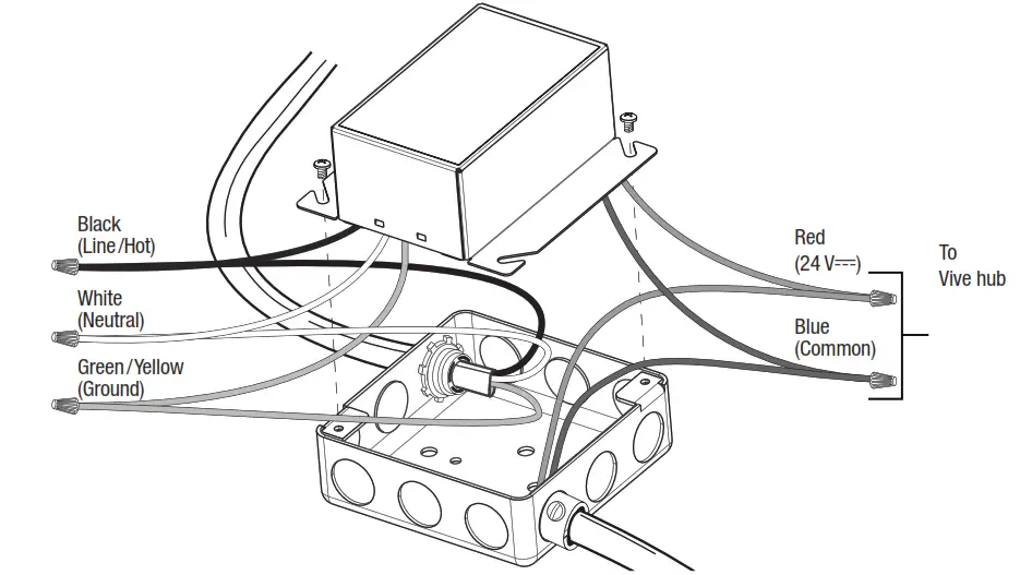
Wiring
A. Power Supply
- Ground the junction box in accordance with NEC® / local codes.
- Mount the power supply to the junction box. The power supply must be mounted within 100 ft (30 mm) of the Vive hub.
- Make wiring connections as shown.
Note: DO NOT power the Vive hub with an Uninterruptable Power Supply (UPS) or emergency generator power. The Vive hub must be powered with normal power only when emergency PowPak /Fixture Controllers are utilized in the system. If the Vive hub is powered from UPS or emergency generator power any emergency PowPak utilized in the system will either not enter emergency mode, or exit emergency mode prematurely.
Note: Maintain separation of the power supply Class 2 output wiring from all other conductors by a minimum of 1/4 in (6.4 mm) or by a non-conductive sleeve or non-conductive barrier.
B. Vive Hub
- Run the low-voltage wiring from the power supply to the Vive hub. Most applications will require an additional length of wire to connect the junction box with the Vive hub. Wiring should be 24 AWG–12 AWG (0.2 mm 2–2.5 mm 2).
- Wire the Vive hub terminal block. Contact Closure Input 1 (CCI1) is programmed by default to meet Title 24 Automatic Demand Response (where applicable). Closing this input will shed the lighting load by 20% for connected Vive compatible lighting devices. Contact Closure Input 2 (CCI2) is programmed by default to have no effect. CCI2 can be configured during programming.
Note: Terminal blocks are removable for ease of wiring.
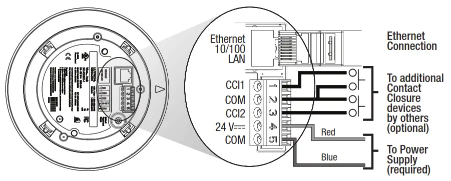
3. Connect the Ethernet cable to connect to Building Management Systems, wired networks, and other Vive hubs.
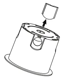
Attaching the Vive Hub to the Adapter
Note: Prior to installing the hub, record the Wi-Fi SSID printed on the label. Attach the Vive hub into the ceiling-mount adapter by inserting and twisting in a clockwise direction until the hub locks into place.
Turn ON power at circuit breaker.
Programming
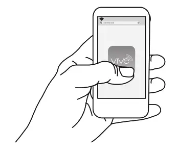
The Vive hub can be set-up easily with any Wi-Fi enabled iOS® or Android® compatible device.
a. Download the Lutron Vive app.

b. Open the app and follow the instructions.
| LED Feedback | |
| Mode / Error | LED Pattern Description |
| Normal Operation | Blink White once every 10 seconds |
| Software update | Blink alternately between Blue and White |
| Reset to factory defaults | Blink alternately between Green and Amber |
| Recovery | Solid Blue |
| Troubleshooting | www.lutron.com/vive |
| Symptom | Possible Solutions |
| Forgot password | • Hold the button on the back of the Vive hub for 30 seconds or until the LED flashes white. |
| Cannot connect over Wi-Fi | • Move closer to the Vive hub. • Verify that the power is connected to the hub. • Check Wi-Fi settings on the smart device. • Connect over the Ethernet and verify that the Wi-Fi is enabled on the hub (see Wi-Fi settings). |
| Cannot connect over Ethernet | • Verify that the power is connected to the Vive hub. • Verify that the wired Ethernet is connected properly. • Verify that the Ethernet cable is less than 328 ft (100 m) in length. |
| LED is Off | • Verify that the power is connected to the Vive hub. • LED should blink once every 10 seconds if the Vive hub is powered properly. |
| LED is red | • Contact Lutron only if maintained more than 30 seconds or occurs periodically. |
| LED is blue | • Contact Lutron. |
| External events (such as Automatic Demand Response) are not triggering | • Verify the contact closure input 1 is connected. • Check the programming for contact closure inputs. |
Customer Assistance:
U.S.A. / Canada / Caribbean: 1.844.LUTRON1
Mexico: +1.888.235.2910
Others: +1.610.282.3800
www.lutron.com/support
Limited Warranty: warranty [PDF]
For FCC/IC information: Please visit: Lutron FCC ID Filings

Lutron Electronics Co., Inc.
7200 Suter Road
Coopersburg, PA 18036-1299 USA
Lutron, Clear Connect, PowPak, and Vive are trademarks or registered trademarks of Lutron Electronics Co., Inc. in the US and/or other countries. Safari is a trademark of Apple Inc., registered in the U.S. and other countries. All other product names, logos, and brands are property of their respective owners.
© 2015-2021 Lutron Electronics Co., Inc.
![]()
Quantum Select
Light Management Hub (QP3)
Centralized Control Equipment
Quantum Light Management Hub (QP3) for Quantum Select
The Quantum Light Management Hub (QP3) connects Lutron QS devices, Lutron power panels, and DMX-512 devices to your Quantum lighting control system.
Features
- Designed to control, manage, and monitor Lutron Energi Savr Node units, Lutron power panels, GRAFIK Eye QS units, Sivoia QS shade/drapery systems and
DMX-512 devices. - The small size of 9.25 in x 3.16 in x 13.25 in (235 mm x 80.3 mm x 337 mm) allows almost any space to be enhanced with Quantum light management.
- Supports both astronomic and time-of-day events to automatically control the lights and shades/draperies in the system.
- Simple reconfiguration of space without rewiring.
- Individually control, monitor, and adjust any light or shade/drapery in a space.
- Can be connected to other Quantum Light Management Hubs.
- Enables a Quantum system to cost-effectively scale from a single floor to multiple floors, to the whole building, and to the whole campus.
Panel Capabilities
- Each Quantum Light Management Hub (QP3) has 2 links that can be individually configured to communicate with:
– Lutron power panels
– Lutron QS devices
– DMX-512 devices for lighting zones (use QSE-CI-DMX for DMX integration zones)
Allowed combinations of links for any single processor:
| DMX-In | DMX-Out | QS | Panel | DBI | |
| DMX-In | ✓ | ✓ | |||
| DMX-Out | ✓ | ✓ | |||
| QS | ✓ | ✓ | ✓ | ✓ | ✓ |
| Panel | ✓ | ✓ | ✓ | ||
| DBI | ✓ | ✓ | ✓ | ✓ |
Specifications
Regulatory Approvals
- UL®
- cUL®
- CE
- NOM dictum per NOM-019
- Complies with requirements for use in other spaces used for environmental air (plenums) per NECR 2014 300.22(C)(3)
- Meets the Canadian National Building Code plenum requirements for a concealed space used as a plenum within a floor or roof assembly
Power
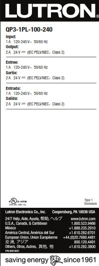
- Input voltage: 120–240 V~ 1 A normal / emergency feed* 50 / 60 Hz
- Output: Processor: 24 V- 2 A
Physical Design
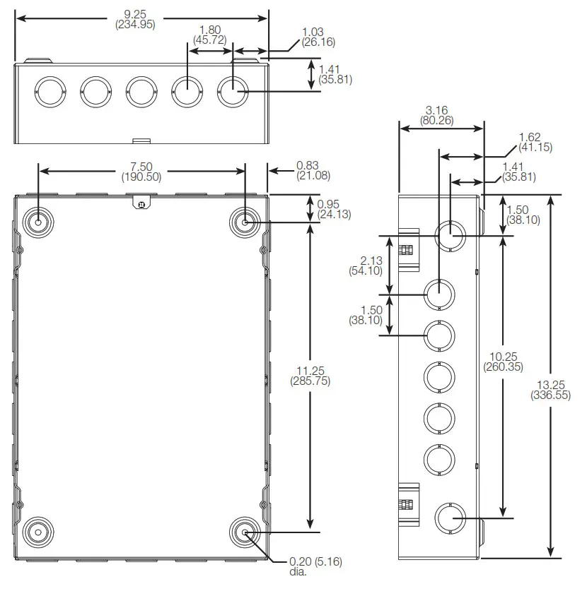
- Enclosure: L: 9.25 in (235 mm)
W: 3.16 in (80.3 mm)
H: 13.25 in (337 mm) - Weight: 11 lb (4.9 kg)
- NEMA Type 1, IP-20 protection
Performance - ± 6 kV surge protection (ANSI / IEEE C62.41-1991)
Mounting - Surface-mount only
Environment - For indoor use only
- 32 ºF to 104 ºF (0 ºC to 40 ºC)
- Relative humidity less than 90% non-condensing
Available Models - QP3-1PL-100-240
Emergency feed is recommended so that the system status can be monitored during an emergency event. If this is not required, normal power can be used.
Dimensions
Shown as in (mm)
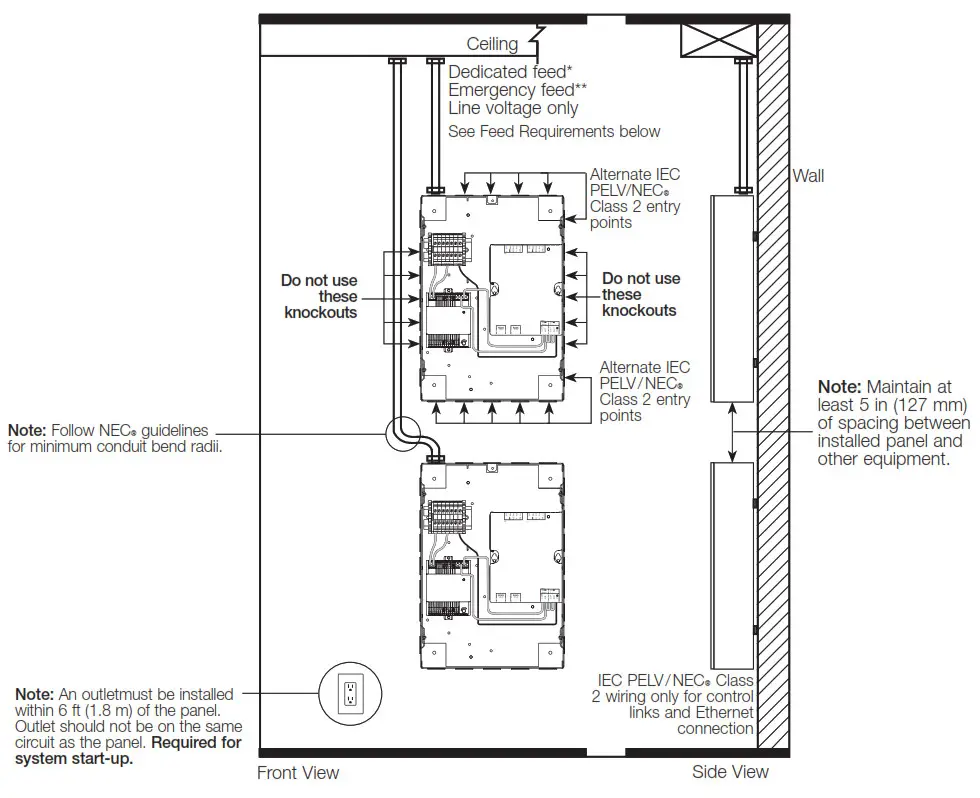
Mounting and Conduit Entry
- Surface mount indoors.
- Panel generates heat, maximum 255 BTUs / h. Mount only where the temperature will be 32 ˚F to 104 ˚F (0 ˚C to 40 ˚C).
- Water damages equipment. Mount in a location where the panel and processors will not get wet.
- Mount in an accessible and serviceable location.
- An outlet must be installed within 6 ft (1.8 m) of the panel for servicing. The outlet should not be on the same circuit as the panel.
- A Light Management Hub (QP3) may be mounted above, below, or beside another Light Management Hub (QP3). Maintain at least 5 in (127 mm) of spacing between the installed panel and other equipment, and follow NECR guidelines for minimum conduit bend radii.
Feed Requirements
* Lutron recommends using a dedicated circuit for lighting control devices.
** Emergency feed is recommended so that the system status can be monitored during an emergency event. If this is not required, normal power can be used.
Panel Overview
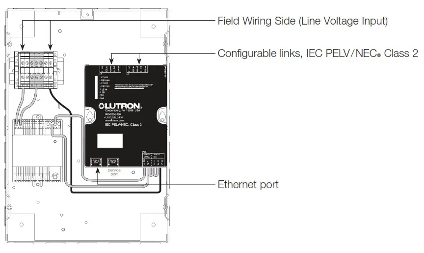
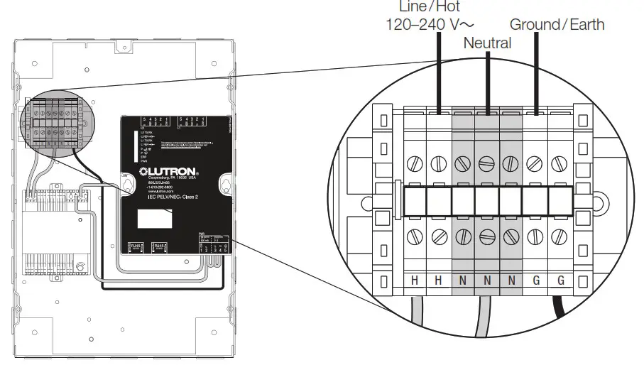
Line Voltage Wiring
 Notes
Notes
- Line voltage must enter panel from top left of the enclosure
- Run wiring so line (mains) Class 1 voltage is separate from IEC PELV / NECR Class 2 wiring
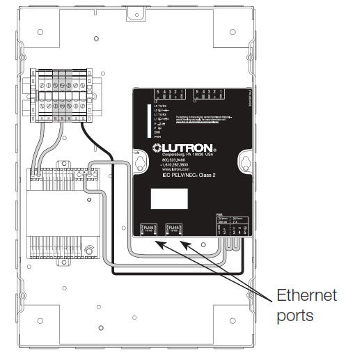
Quantum Inter-Processor Link Wiring
Notes
- The inter-processor wiring is considered IEC PELV / NECR Class 2; do not run in the same conduit as line (mains) voltage wiring.
- Interprocess communication uses a standard Ethernet connection. All wiring must comply with IEEE 802.3 standards and must support Any-Source Multicast communication.
- Processors cannot be daisy-chained. Each must be connected to an Ethernet switch.
- Wiring distance for any single “wire segment”* is 330 ft (100 m) max; use unmanaged Ethernet switches for longer distances.
- Processors cannot be more than 6 “wire segments” from the server.
- A dedicated network or VLAN is recommended for the lighting control system.
- For more information about connecting a Quantum system to a corporate or building-wide network, please refer to the Quantum IT Guide (P/N 040423) at 040423 [PDF]
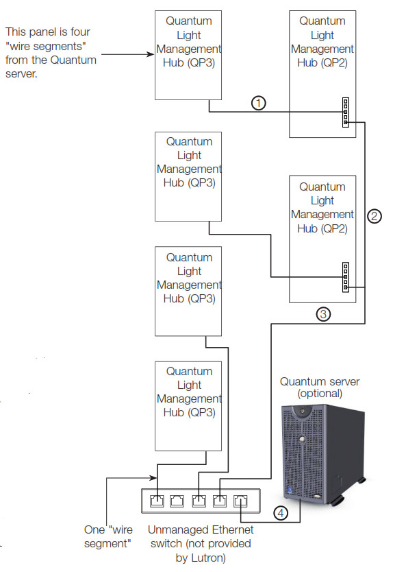
* A wire segment is a length of cable connecting two devices communicating over Ethernet.
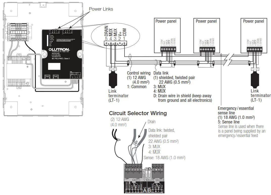
Configurable Link Wiring: Power Panel Link
 Notes
Notes
- The power panel link must be daisy-chained (no T-taps).
- Maximum of 32 circuit selectors per link or 512 switch legs (controllable outputs) per link.
- It is not necessary to have the Quantum panel at the end of the link (it may be in the middle).
- The sense wire (terminal 5) is used whenever there is a panel being supplied by an emergency / essential feed; see power panel instructions for details.
- Each low-voltage IEC PELV / NECR Class 2 terminal can accept only two 18 AWG (1.0 mm2 ) wires or one 12 AWG to 22 AWG (4.0 mm2 to 0.5 mm2 )
wire. Connect as shown using appropriate wire connectors. - The total length of the control link may be no more than 2000 ft (610 m). Lutron Model: MX-RPTR can be used to extend the link beyond 2000 ft (610 m).
Contact Lutron for more information. - GRX-CBL-46L wiring cable is available from Lutron and contains two 12 AWG (4.0 mm2 ) conductors for control power, one twisted, shielded pair of 22 AWG (0.5 mm2 ) for data link, and one 18 AWG (1.0 mm2 ) conductor for emergency (essential) sense line.
Configurable Link Wiring: QS Link
QS Link Wiring:
• 22 AWG to 12 AWG (0.5 mm( to 4.0 mm²)
| Availble Power Draw Units (PDUs) per link |
Maximum Link Length |
Wire Gauge | Available from Lutron in one cable |
| 33 | 500 ft (152 m) |
Power (terminals 1 and 2) 1 pair 18 AWG (1.0 mm2) 1 pair 22 AWG (0.5 mm2) twisted and shielded |
GRX-CBL-346S GRX-PCBL-346S |
| 33 | 2000 ft (610 m) |
Power (terminals 1 and 2) 1 pair 12 AWG (4.0 mm2) Data (terminals 3 and 4) 1 pair 22 AWG (0.5 mm2) twisted and shielded |
GRX-CBL-46L GRX-PCBL-46L |
Notes
- System communication uses IEC PELV/NECR Class 2 low-voltage wiring.
- Follow all local and national electrical codes when installing IEC PELV / NECR Class 2 wiring with line voltage/mains wiring.
- Each terminal accepts two 22 AWG – 18 AWG (0,5 mm² – 1.0 mm²) wires or one 22 AWG –12 AWG (0.5 mm² – 4.0 mm²) wire.
- Make all connections inside the control unit’s wall box.
- A Quantum QS link can have up to 512 switch legs (controllable outputs) and 99 Lutron QS devices. Refer to the QS Link Power Draw Units Specification Submittal (Lutron P/N 369405) at www.lutron.com and the table above for information concerning Power Draw Units (PDUs).
- QS link wiring can be T-tapped or daisy-chained.
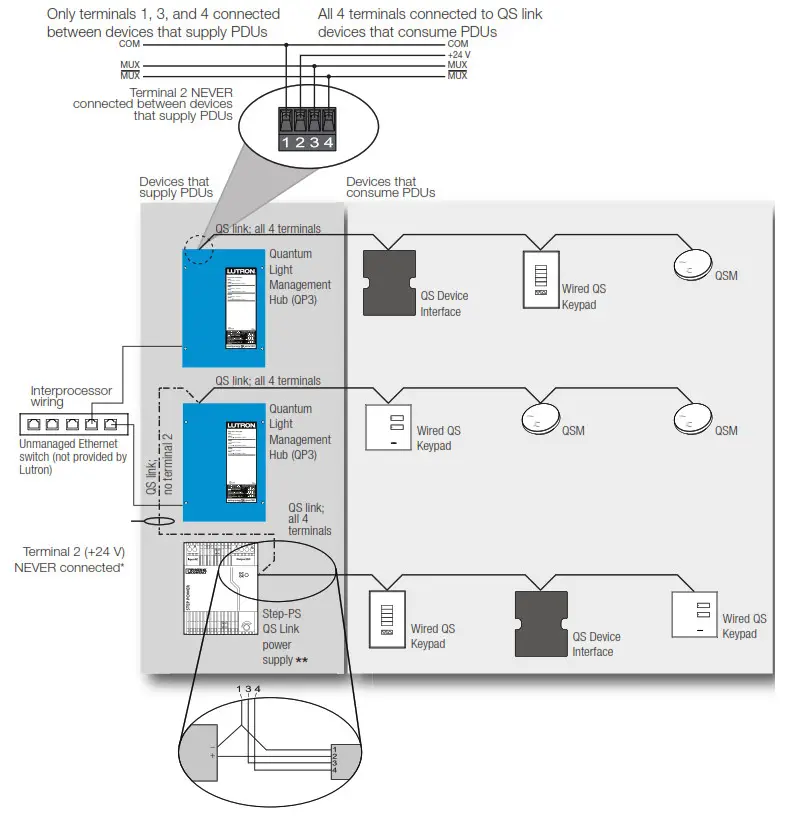
QS Link Wiring Rules
* Terminal 2 (+24 V) should NEVER be connected between devices that supply PDUs.
** For QS Link power supply wiring connection details, refer to the installation instructions for the specific power supply model being used.
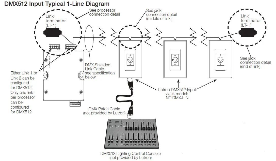
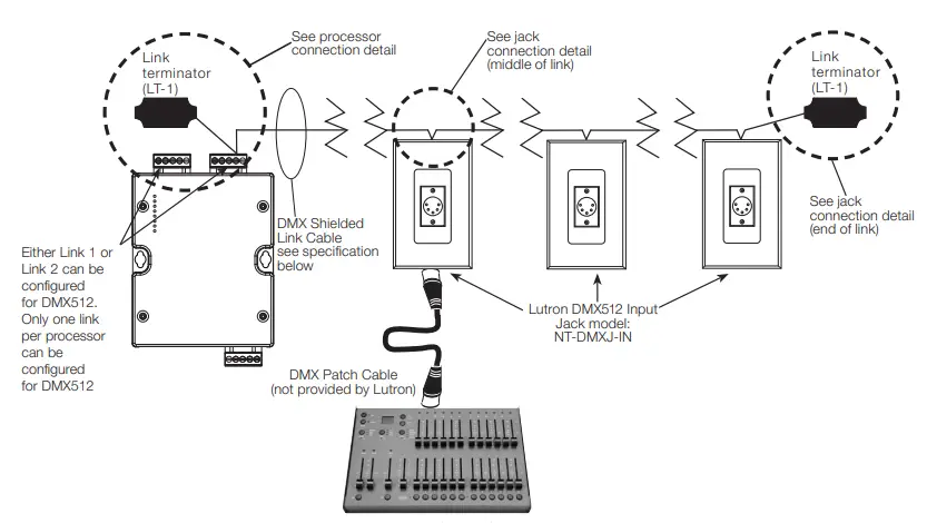
Note: If connecting more than one jack to the processor, only one DMX512 lighting control console can be connected to a link at the same time. If multiple consoles need to be connected at the same time, a merger should be used. See Application Note # 592 (P/N 048592) for more information.
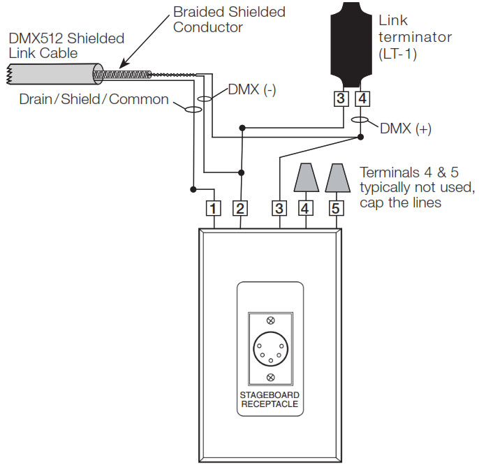
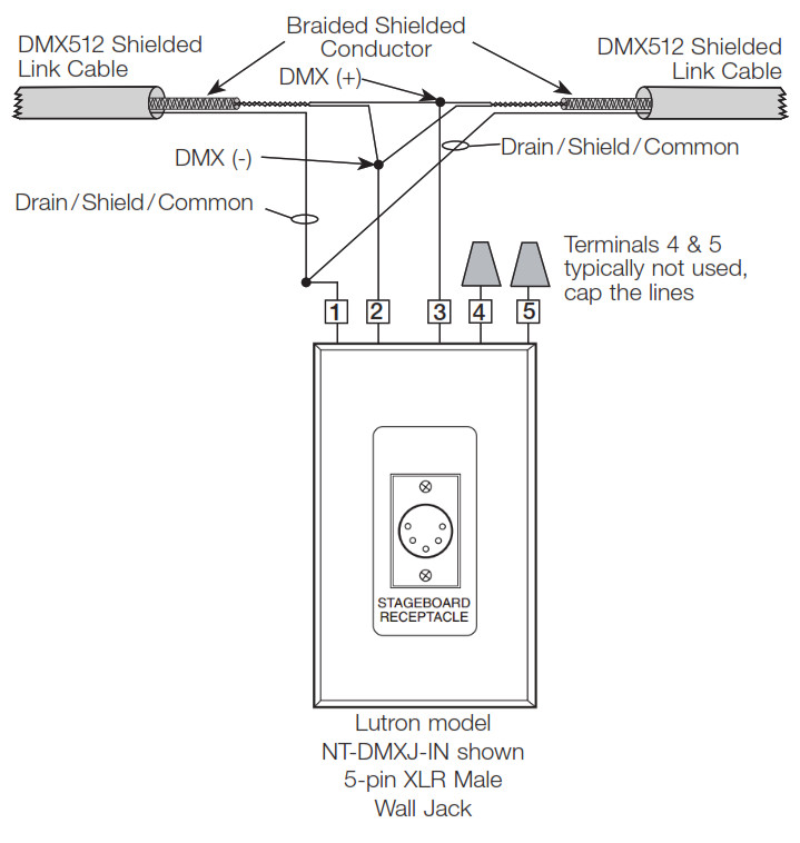
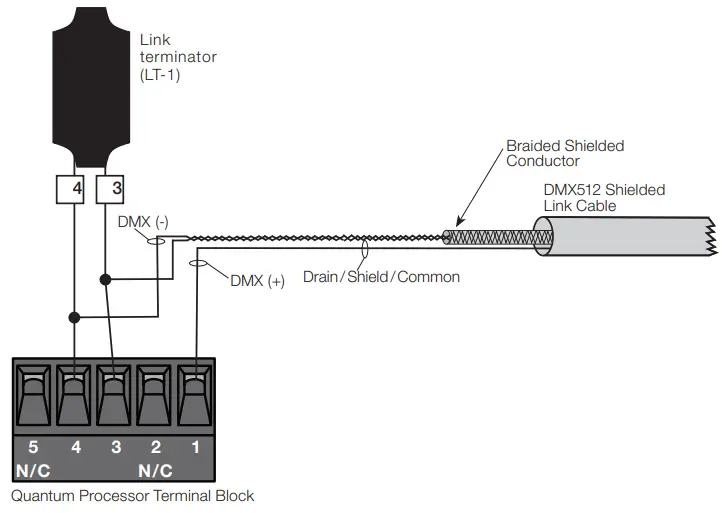
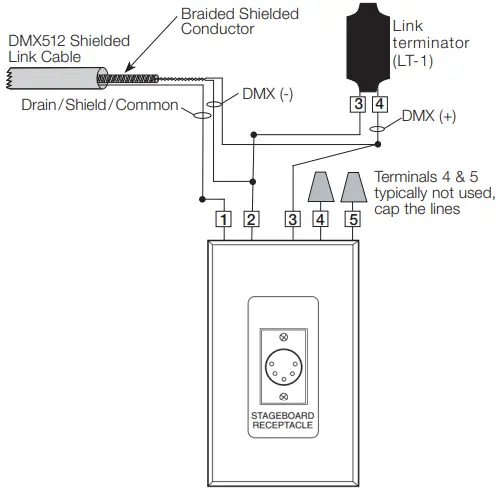
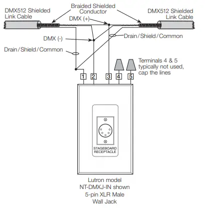
DMX512 Quantum Processor Connection Details
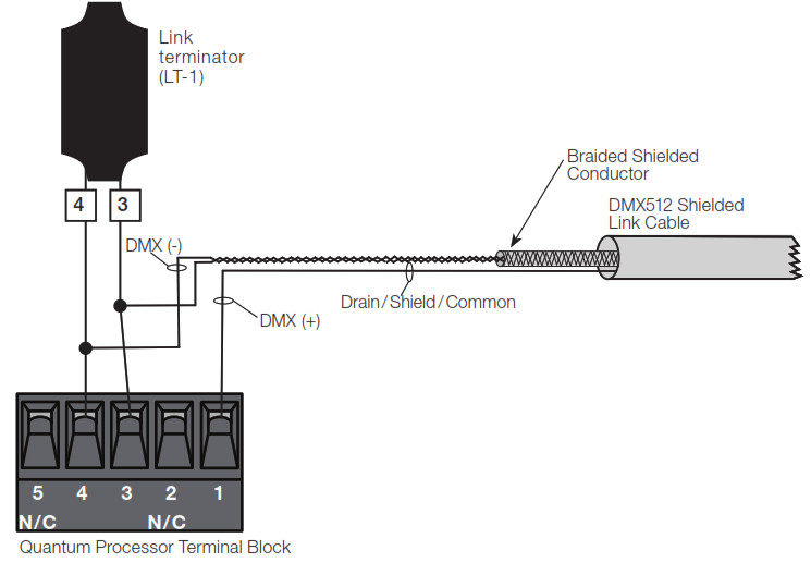
Jack Connection Detail (End of Link)
Jack Connection Detail (Middle of Link)
Alternate XLR Jack Pinouts
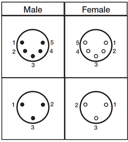
DMX XLR Jack Pinout Standard
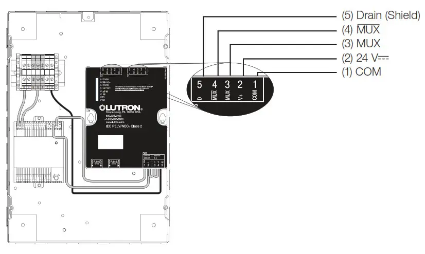
| 1 | Drain/Shield/Common |
| 2 | DMX (-) Primary Link |
| 3 | DMX (+) Primary Link |
| 4 | DMX (-) Secondary Link |
| 5 | DMX (+) Secondary Link |
DMX Cable Wiring Table
The table below provides information pertaining to Lutron-provided (optional) DMX cable and how it should be terminated. For third-party cable, consult with the manufacturer for their connection recommendations and always shielded cable that complies with the ANSI E1.11-2008, USITT DMX512-A standard.
| Manufacturer | Model | Signal Name | Wire Color | Lutron model NT-DMXJ-IN connection | Lutron Quantum Procesor Connection |
| Lutron | GRX-CBL-DMX-250 or GRX-CBL-DMX-500 | Drain/Shield/Common | Use braided wire that the twisted airs‘-‘ |
Pin 1 – Drain/Shield/ Common (white with black stripe) | Pin 1 – Common |
| DMX (-) Primary Link | White or pink | Pin 2 – DMX (-) Primary Link (red) | |||
| Pin 4 – MUX | |||||
| DMX (+) Primary Link | Black | Pin 3 – DMX (+) Primary Link (yellow) | Pin 3 – MUX | ||
| DMX (-) Secondary Link | Green | Pin 4 – DMX (-) Secondary Link (blue) | No connection (cap the wire) | ||
| DMX (+) Secondary Link | Red | Pin 5 – DMX (+) Secondary Link (black) | No connection (cap the wire) |
Notes
- Installation and all devices must comply with the ANSI E1.11-2008, USITT DMX512-A standard.
- Below are a few Important points from the standard:
– All DMX512 devices in a DMX512 universe must be wired in a daisy-chain configuration.
– Total length of the link wiring for one DMX512 universe must not exceed 1000 ft (305 m). DMX repeaters or splitters can be used to extend the link. All repeaters must comply with the standard.
The repeater manufacturer’s guidelines must be followed.
– All cable used must comply with the standard.
Lutron models GRX-CBL-DMX-250 and
GRX-CLB-DMX-500 comply with the standard and are recommended.
– DMX512 link terminators must be installed at both ends of the DMX512 link. Lutron model LT-1A link terminators are included with the panel and are recommended. Note that some DMX512 devices have built-in link terminators.
– A maximum of (31) DMX512 devices can be directly connected to the DMX512 controller. If (32) or more devices are required, DMX512 repeaters or splitters must be used. A repeater or splitter is needed so that no more than (32) devices are directly connected on the same wire segment.
Note that link terminators are required at the beginning and end of every wire segment. - The Quantum processor can be programmed to either control DMX512 devices (DMX512 output) or to receive DMX512 signals from a DMX512 controller
(DMX512 input) such as a theatrical stage board. - All wiring must be low-voltage IEC PELV/NECR Class 2 wiring. Each terminal of the Lutron processor can accept only stranded wire, and either (1 or 2) 22–18 AWG (0.5 mm² – 1.0 mm²) conductors or(1) 16–12 AWG (1.5 mm² – 4.0 mm²).
- The Quantum processor can be at the end or in the middle of the DMX512 link. The link terminators must always be installed at the ends of the link.
- Only one link of the processor can be configured as a DMX512 link. The other link of the processor must be configured as a QS link.
- DMX512 devices must be addressed prior to the commissioning of the system. A schedule of the DMX devices and their addresses must be supplied to the Lutron project manager prior to commissioning. Lutron is not responsible for the addressing of the DMX512 devices.
- Refer to the Lutron DMX512 Application Note #592 (P/N 048592) at www.lutron.com for information on the different DMX512 applications that Lutron can provide.
The Lutron logo, Lutron, Energi Savr Node, GRAFIK Eye, Sivoia, and Quanta are trademarks or registered trademarks of Lutron Electronics Co., Inc. in the US and/or other countries.
All other product names, logos, and brands are the property of their respective owners.
![]() SPECIFICATION SUBMITTAL
SPECIFICATION SUBMITTAL
Job Name:
Job Number:
Model Numbers:
DMX Input Software License for Quantum
This license for DMX input software allows a DMX lighting stage board (or other DMX source) to controlthe levels of lights that are part of a Quantum Total Light Management system. Users continue to experience the benefits of Quantum Total Light Management (e.g., scheduled events, occupancy sensing, daylighting, wall-station control) while also maintaining flexible DMX control for setting up light levels during special events.This feature is intended for flexible, static lighting zone adjustment; it is not intended to manage continuously changing light levels (e.g., theatrical lighting.
Model Number
QSW-DMX-IN
Features
- Supports up to 512 input channels per processor on a single universe.
- An input channel controls a single lighting zone in the system.
- DMX input control can be enabled and disabled on an area-by-area basis.
- Enabling and disabling DMX is achieved by activating or deactivating the DMX scene in an area.
- Enabling and disabling the DMX scene in an area can be activated through a timeclock event, contact closure input, or keypad button press.
- DMX control must be enabled by activating the specified DMX scene before DMX zone control can take place in that area. This can be accomplished via contact-closure input, wall station, keyswitch control, Quantum Vue or other programmable input.
- Supports zone chaining for partitioned spaces.
- Supports a sustained rate of up to five constantly changing channels at any one time.
Capabilities
- Adjusts a given zone level up to 10 times / second in response to DMX input.
- Supports a burst rate of up to 500 zone level adjustments / second for a maximum of 10 seconds.
- Each input channel can control a single lighting zone (dimmed or non-dimmed)
Requirements
- Requires a dedicated link on a Quantum processor that will be controlling zones using a DMX input. – Only one link per processor can be dedicated for DMX, with a maximum of 512 inputs on this link. – Each input can be mapped to only one zone. The zone must be in the same logical processor subsystem as the DMX input that is controlling it.
- When controlling the zones in an area from another source (e.g., a wall station, scheduled event, Quantum Vue software), the zones in that area will exit the DMX scene. To prevent this from happening, these sources must be locked or disabled.
- The lights in an area will not respond to DMXcommands unless the DMX scene is active in that area.
- One license is required for each processor. The license is only required for processors that manage the zones being controlled via a DMX input.
- This license must be activated by Lutron Field Service.
- Requires Quantum version 3.1 or higher.
Limitations
- If daylighting is enabled on all scenes in an area, the DMX scene will also be daylighted
- DMX inputs cannot be mapped to 3-channel DMX zones or to a GRAFIK Eye QS zone.
- The DMX input control is only compatible with the following Lutron lighting controllers:
- GP dimming panels
- LP dimming panels
- CCP dimming panels
- XP switching panels
- Energi Savr Node 0–10 V- modules
- Energi Savr Node switching modules
- Energi Savr Node phase-adaptive modules
- EcoSystem devices connected directly to QP2 hubs
Note: DALI devices, EcoSystem devices connected to a GRAFIK Eye QS unit, and Eco System devices connected to an Energi Savr Node with EcoSystem unit cannot be controlled via the DMX input control feature.
Best Practices
• See Application Note #592 Lutron Solutions for DMX512-A (www.lutron.com/TechnicalDocumentLibrary/048592.pdf)
SPECIFICATION SUBMITTAL
| Job Name:__________________ | Job Name:_________ |
| Job Name:_______________ | ________________ _________________ |
Wiring
DMX512 Input Typical 1-Line Diagram

Note: If connecting more than one jack to the processor, only one DMX512 lighting control console can be connected to a link at the same time. If multiple consoles need to be connected at the same time, a merger should be used.
See Application Note # 592 (P/N 048592) for more information.
DMX512 Quantum Processor Connection Details
Wiring
Jack Connection Detail (End of Link)
Jack Connection Detail (Middle of Link)
DMX XLR Jack Pinout Standard
- Drain/Shield/Common
- DMX (-) Primary Link
- DMX (+) Primary Link
- DMX (-) Secondary Link
- DMX (+) Secondary Link
DMX Cable Wiring Table
The table below provides information pertaining to Lutron-provided (optional) DMX cable and how it should be terminated. For third-party cable, consult with the manufacturer for their connection recommendations and always use shielded cable that complies with the ANSI E1.11-2008, USITT DMX512-A standard.
| Manufacturer | Model | Signal Name | Wire Color | Lutron model NT-DMXJ-IN connection | Lutron Quantum Procesor Connection |
| Lutron | GRX-CBL-DMX-250 or GRX-CBL-DMX-500 | Drain / Shield / Common | Use braided wire that surrounds the twisted pairs | Pin 1 – Drain / Shield / Common (white with black stripe) | Pin 1 – Common |
| DMX (-) Primary Link | White or pink | Pin 2 – DMX (-) Primary Link (red) | Pin 4 – _ | ||
| DMX (+) Primary Link | Black | Pin 3 – DMX (+) Primary Link (yellow) | Pin 3 – MUX | ||
| DMX (-) Secondary Link | Green | Pin 4 – DMX (-) Secondary Link (blue) | No connection (cap the wire) | ||
| DMX (+) Secondary Link | Red | Pin 5 – DMX (+) Secondary Link (black) | No connection (cap the wire) |
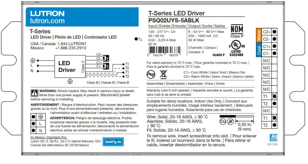
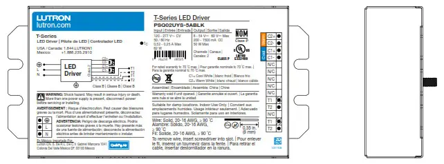
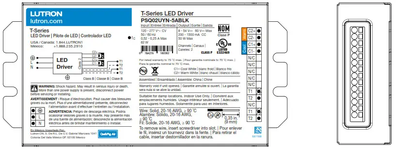
T-Series LED Driver
T-Series LED Driver
T-Series LED Drivers provide a high-performance tunable white solution.
Features
- ULR 8750 Listed Class P
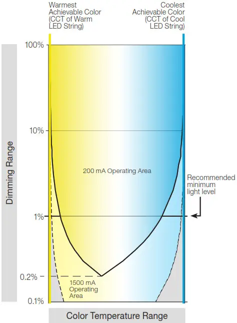
- Each output capable of 100% to 0.1% dimming *
- For best tunable white performance, operate at 1% or higher. See page 10 for more details
- Dimming Method:
– Constant-current reduction (CCR) dimming to 200 mA
– Pulse-width modulation (
PWM) dimming below 200 mA
PWM Frequency = 3.6 kHz
outputs of the two channels are synchronized - Driver consumes two digital addresses: one for intensity and one for color temperature
- Guaranteed performance and compatibility when used with Lutron T-Series controls:
– T-Series Energi Savr Node unit as part of a Quantum system - Guaranteed compatibility with T-Series Energi Savr Node as a part of a Quantum system
- QwikFig Air compatible
- Protected from miswires of input power to T-Series control inputs up to 277 V~
- A rated lifetime of 50,000 hours at 167 °F (75 °C)
calibration point (TC) for W case and 158 °F (70 °C)
calibration point (TC) for Y case - FCC Part 15 Class A
- 100% performance tested at factory before shipping.
- RoHS compliant
- For more information please visit: www.lutron.com

Case Type W
1.18 in (30 mm) W x 0.83 in (21.0 mm) H x 16.06 in (408 mm) L

Case Type YS
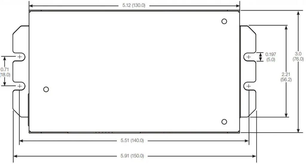
3.0 in (76.0 mm) W x 1.14 in (29.0 mm) H x 5.91 in (150.0 mm) L
Case Type YN
3.0 in (76.0 mm) W x 1.14 in (29.0 mm) H x 5.91 in (150.0 mm) L
T-Series Digital Link Features
- Simpler to wire and more reliable than 0 –10 V
- Guarantees compatibility between Lutron controls and LED drivers
- Accommodates zone and control changes without rewiring
- Connect to Quantum Total Light Management Systems to monitor lighting power consumption
- Polarity-free and topology-free
- Allows easy code compliance
- T-Series digital link can be Class 1 or Class 2
- Non-volatile memory restores all settings after power failure

Specifications
Regulatory Approvals and Compliance
- cULus Listed Class P
- NOM certified
- Lutron Quality Systems registered to ISO 9001.2015
- Inrush current less than NEMA 410-2011 limit
- FCC Part 15 Class A
- Meets UL® 8750, “Light Emitting Diode (LED) Equipment For Use in Lighting Products”
- Class 2 outputs
- Compliant with performance criteria for ENERGY STAR for Luminaires Version 2.1 in designated areas (see Load Compatibility graph in Output Ranges page 6)
- Compliant with DLC version 4.3 in designated areas (see Load Compatibility graph in Output Ranges page 6) (for W case only)
Performance
- Dimming Range: 100% to 0.1%1
- Operating Voltage: 120 V~ / 277 V~ at 50 / 60 Hz
- Lifetime: 50,000 hours when calibration point (tc) at 167 °F (75 °C) for W case and 158 °F (70 °C) for Y case 2
- ULR allows operation of t c up to 90 °C
- For rated warranty, tc not to exceed 167 °F (75 °C) for W case and 158 °F (70 °C) for Y case (maximum rated temperature)2
- At turn-on, lighting goes to the desired level without decreasing or flashing to full brightness
- Typical standby power consumption: < 0.5 W at 120 V~ / 277 V~
- Open-circuit protected output
- Short-circuit protected output
- Over-temperature protected
Environmental
- Sound rated: Class A inaudible in 24 dBA ambient
- Relative Humidity: maximum 90% non-condensing
- Minimum Operating Ambient Temperature:
ta = 0 °C (32 °F)3 - Indoor use only
- Rated for dry and damp locations
OEM Notes
- For best dimming performance, Lutron recommends electrical insulation with 50 / 60 Hz impedance of at least 12 MΩ and minimum breakdown voltage of at least 1500 V~ between LEDs and fixture chassis
Driver Wiring and Mounting
- Driver is grounded by a mounting screw to the grounded fixture or by a terminal connection.
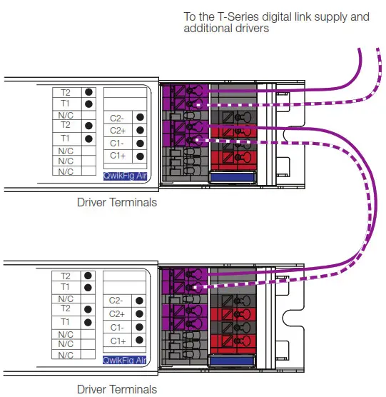
- It is possible to daisy-chain the T-Series digital link using the second set of terminal blocks. See example on page 10
- Fixture must be grounded in accordance with local and national electrical codes
- The positive terminals of both output channels are electrically connected inside the driver. This supports the use of common anode loads
- Terminal blocks on the driver accept one solid wire per terminal from 20 AWG to 16 AWG (0.5 mm)
- Maximum driver-to-LED light engine wire length for:
| Wire Gauge | Maximum Lead Length | ||
| 150 mA to 700 mA |
710 mA to 1.50 A |
1.51 A to 2.10 A |
|
| 18 AWG (0.75 mm2) | 30 ft (9 m) | 15 ft (4.5 m) | 10 ft (3 m) |
| 16 AWG (1.5 mm2) | 35 ft (10.5 m) | 25 ft (7.5 m) | 15 ft (4.5 m) |
| 14 AWG (2.5 mm2)4 | 50 ft (15 m) | 40 ft (12 m) | 25 ft (7.5 m) |
| 12 AWG (4.0 mm2)4 | 100 ft (30 m) | 60 ft (18 m) | 40 ft (12 m) |
- For best tunable white performance, operate at 1% or higher. Light output at the low-end depends on the efficacy of the LED light engine used with the driver.
- To maintain the warranty, the installer is responsible for ensuring that the driver calibration point does not exceed 167 ºF (75 ºC) for W case and 158 ºF (70 ºC) for Y case.
- Where ta is the temperature of the air directly surrounding the driver.
- Terminal blocks on the drivers accept only solid 20 AWG to 16 AWG (0.5 mm 2to 1.5 mm 2 ) wire. To use wire gauges larger than the terminal blocks’ rated gauge of 16 AWG (1.5 mm 2 ), connect up to 3 ft (1.0 m) of 20 AWG to 16 AWG (0.5 mm 2 to 1.5 mm 2 ) wire to the LED driver terminal blocks, then connect 12 AWG or 14 AWG
(4.0 or 2.5 mm 2) up to the length allowed in the above table.
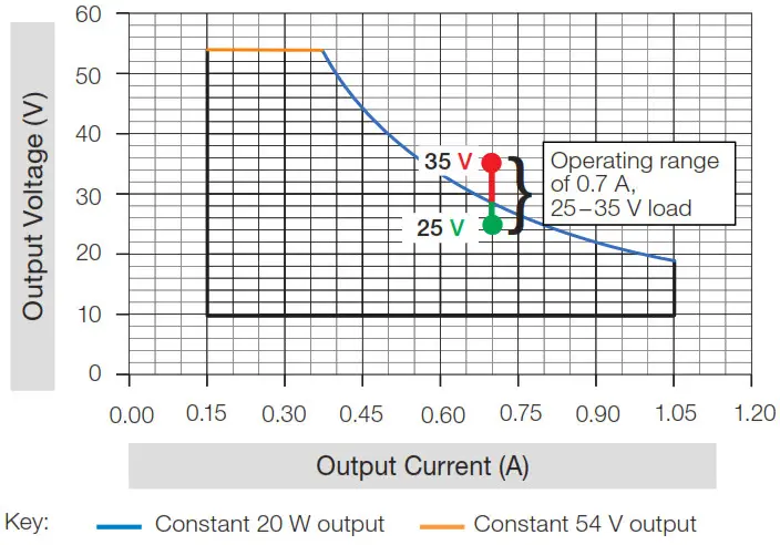
How to Determine Compatibility Between an LED Driver and LED Load
- Review the specifications of the LED load.
- Identify the minimum and maximum operating voltage of the LED load at the desired operating current. This “current” will be the rated output current of the LED driver. Consult the LED load manufacturer for any questions.
Example: An LED load that is rated at 0.7 A and 30 V nominally, has an input (forward) voltage range of
25 – 35 V (at 0.7 A) due to unit-to-unit variation, temperature, etc. - Examine the LED driver Load Compatibility graphs below for each output range to ensure that the voltage range of the LED load is within the load compatibility range.
Example: Lines* marked below indicate two load specifications:
Load A (25 – 35 V) at 0.5 A
Load B (25 – 35 V) at 0.7 A
Load A (Compatible)
The operating voltage range for load A is 25 – 35 V at 0.5 A. Since the load specifications are within the operating range, the combination of LED load and LED driver is compatible.

Load B (Not Compatible)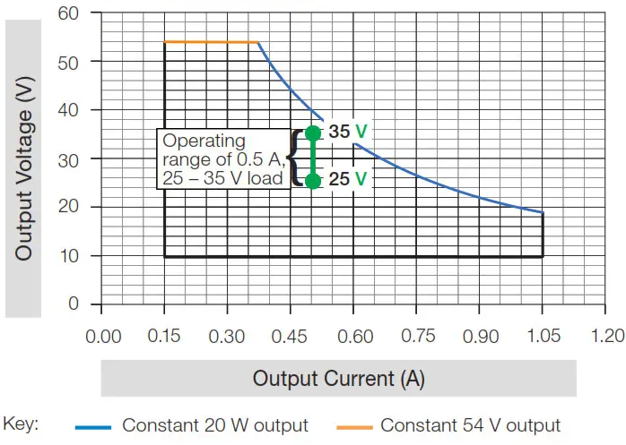
Since the maximum voltage of the load, 35 V, exceeds the 28.5 V allowable at 0.7 A, this combination of LED load and LED driver is not compatible.
Load Compatibility

4.The LED Driver Selection Tool (www.lutron.com/drivers) is a website compatibility tool that allows for a fast compatibility search of all Lutron LED drivers that are compatible with an LED load.
5See T-Series Model Number to create the appropriate model number for the desired driver. T-Series drivers are only available as “BLK” drivers for use with QwikFig Air.
* Lines are an example and not the range of the T-Series LED driver.
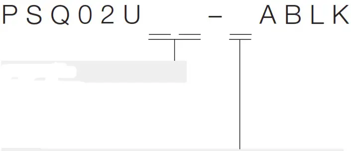
T-Series Model Number
W-case type

YS-case type
YN-case type
Case Type
• WN: W Case Type
• YS: YS Case Type
• YN: YN Case Type
LED Load Output Range: Class 2 Constant Current
(see the following pages for more detail)
• 5: 50 W Max, 0.20 – 1.50 A, 8 – 54 V![]() *
*
* Output voltage range changes with output current and according to power limits. Check driver specifications on the following pages carefully to understand output voltage range of a particular SKU. Purchaser is responsible for electrical compatibility between LED driver and LED load.
“5” Output Range
| Driver Type | Output Voltage | Output Current | Output Power | Standards Recognition | Maximum Rated Temp. g tc for Warranty | |
| W-Case | Constant Current Driver (Class 2) | 8-54 V= | 0.20-1.50 A* | 50 W” | 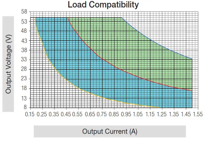 |
75 °C |
| Y-Case | Constant Current Driver (Class 2) | 8-54 V= | 0.20-1.50 A* | 50 W” | |
70 °C |
* QwikFig compatible model number PSQ02UWN-5ABLK is configurable to any current within this range in 0.005 A increments.
** Each channel is capable of delivering 50 W. The combined output of both channels must not exceed 50 W total.
Typical Performance Specifications:
| 277 | 120 V– | ||||
| Parameter | Value | Test Conditions | Value | Test Conditions | |
| Input Current | 0.25 A | 0.5 A | |||
| Power Factor (PF) | 0.95 | 0.99 | |||
| W-Case | Total Harmonic | 7% | 6% | ||
| Distortion (THD) | V; = 277 | V; = 120 | |||
| Driver Efficiency | 87% | ta = 25 °C la = 0.90 A | 87% | ta = 25 °C 10 = 0.90 A | |
| Input Current | 0.22 A | 0.48 A | |||
| Va = 54 V= | Va = 54 V= | ||||
| Power Factor | 0.96 | 0.99 | |||
| Y-Case | |||||
| THD | 9% | 9% | |||
| Driver Efficiency | 88% | 88% | |||
Please see the graphs on the following page.

Key:
Constant 25 W output
Constant 50 W output
Constant 10 W output
Shaded area meets both ENERGY STAR Luminaires V2.1 Specification and DLC Version 4.3 (W case only). Areas outside of shaded areas may not meet THD or PF requirements.
Shaded area meets only ENERGY STAR Luminaires V2.1 Specification. Areas outside of shaded areas may not meet THD or PF requirements.
Typical Power Factor vs Total Power Output
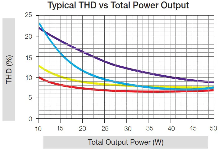
Typical THD vs Total Power Output
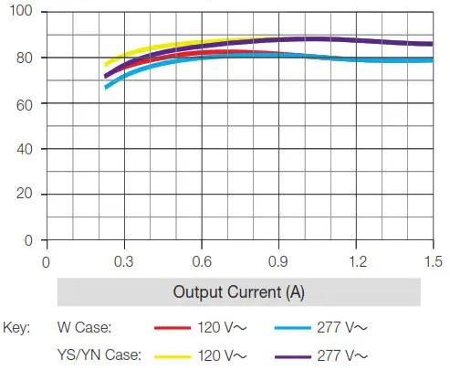
Typical Efficiency vs Output Current
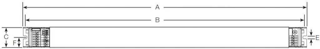
W Case Dimensions
All measurements are shown as: in (mm)
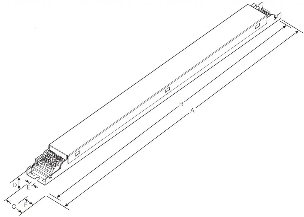
A = 16.06 (408)
B = 15.79 (401)
C = 1.18 (30)
D = 0.827 (21)
E = 0.165 (4)
F = 0.59 (15)
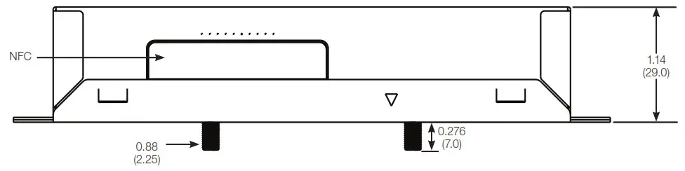
YS Case Dimensions
All measurements shown as: in (mm)
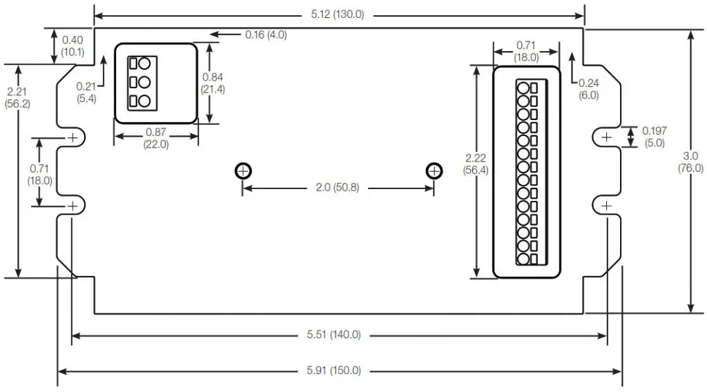
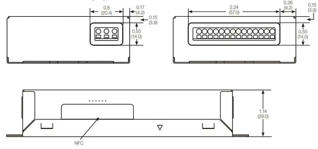
YN Case Dimensions
All measurements shown as: in (mm)
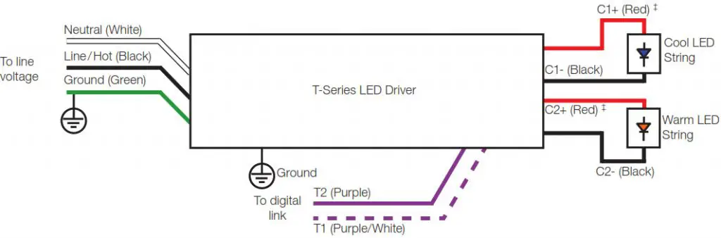
Wiring Diagram
‡C1+ and C2+ are electrically connected inside the driver. This supports the use of common anode loads.
Tunable White Considerations
- The driver will consume two digital addresses:
– Address N controls intensity*
– Address N+1 controls color temperature* - The highest kelvin light source must be connected to channel 1 (cool white).
- The lowest kelvin light source must be connected to channel 2 (warm white).
- The driver can accept LED light sources with a physical CCT value between 1500 K and 6500 K.
- The driver default minimum intensity level is set to 1%.
See the Tunable White Capability figure to the right for more information. - Operation below 1% may be acceptable in some applications. The minimum level can be adjusted below 1% through the Quantum software. See the Tunable White Capability figure to the right for understanding the general trade-off of dimming range versus color temperature range.
- For optimal tunable white performance, it is recommended to set high-end and low-end logical trims which reduce the overall CCT range to less than the maximum capacity of the light source.
Tunable White Capability
* This is the default behavior. During commissioning, the system may change the addresses to be non-consecutive.
Compatible Controls: Lutron T-Series Digital Controls
Guaranteed performance specifications with the controls listed in the chart below.
For assistance selecting controls, contact our LED Center of Excellence at 1.877.346.5338 or [email protected]
| Lutron T-Series Compatible Controls | Part Number | ||||
| 120 V~ | 277~ | T-Series Loops per Control |
T-Series Drivers per Loop |
Total T-Series Drivers per Control |
|
| T-Series Energi Savr Node* | QSN-TW | 2 | 32** | 64 | |
*Must be used as part of a Quantum system version 3.4 or higher.
**Each T-Series loop is capable of having 64 addresses. Each driver consumes two addresses.
T-Series Wiring
T-Series Digital Link Overview
- The T-Series digital link wiring (T1 and T2) connects the digital ballasts and drivers together to form a lighting control system.
- T1 and T2 (T-Series digital link wires) are polarity-insensitive and can be wired in any topology (e.g., T-tap and daisy-chain).
- Power is supplied to the T-Series digital link from the control system.
T-Series Digital Link Wiring - Make sure that the supply breaker to the drivers and T-Series digital link supply is OFF when wiring.
- Connect the two conductors to the two driver terminals T1 and T2 as shown.
- Using two different colors for T1 and T2 will reduce confusion when wiring several drivers together.
- There are two sets of T-Series digital link terminal blocks to support daisy chaining the link.
- The T-Series digital link may be wired Class 1 or Class 2. Consult applicable electrical codes for proper wiring practices. Please refer to Lutron Application Note #142 (048162) at www.lutron.com for more information.
- For emergency lighting wiring, please refer to Lutron Application Note #106 (048106) at www.lutron.com

Notes
• The T-Series digital link supply does not have to be located at the end of the digital link.
• The Maximum Wire Length table below gives the limits for each of the wires in the T-Series digital link pair.
• The T-Series digital link length is limited by the wire gauge used for T1 and T2 as follows:
| Wire Gauge | Maximum Wire Length |
| 12 AWG | 1000 ft |
| 14 AWG | 1000 ft |
| 16 AWG | 900 ft |
| 18 AWG | 550 ft |
| Wire Size | Maximum Wire Length |
| 4.0 mm2 | 300 m * |
| 2.5 mm2 | 300 m * |
| 1.5 mm2 | 300 m |
| 1.0 mm2 | 207 m |
| 0.75 mm2 | 155 m |
Service
Warranty
For warranty information, please visit 3601281_ENG_Web [PDF]
Replacement Parts
When ordering Lutron replacement parts, please provide the full model number. Consult Lutron if you have any questions.
Further Information
For further information, please visit us at
www.lutron.com or contact our LED Control Center of
Excellence at 1.877.346.5338 or [email protected]
 Lutron, Lutron, Energi Savr Node, Quantum, QwikFig, and QwikFig Air are trademarks or registered trademarks of Lutron Electronics Co., Inc. registered in the U.S. and other countries.
All product names, logos, and brands are the property of their respective owners.