![]()
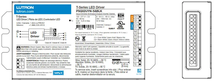
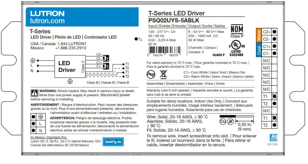
T-Series LED Driver
T-Series LED Driver
T-Series LED Drivers provide a high-performance tunable white solution.
Features
- ULR 8750 Listed Class P
- Each output capable of 100% to 0.1% dimming *
- For best tunable white performance, operate at 1% or higher. See page 10 for more details
- Dimming Method:
– Constant-current reduction (CCR) dimming to 200 mA
– Pulse-width modulation (
PWM) dimming below 200 mA
PWM Frequency = 3.6 kHz
outputs of the two channels are synchronized - Driver consumes two digital addresses: one for intensity and one for color temperature
- Guaranteed performance and compatibility when used with Lutron T-Series controls:
– T-Series Energi Savr Node unit as part of a Quantum system - Guaranteed compatibility with T-Series Energi Savr Node as a part of a Quantum system
- QwikFig Air compatible
- Protected from miswires of input power to T-Series control inputs up to 277 V~
- A rated lifetime of 50,000 hours at 167 °F (75 °C)
calibration point (TC) for W case and 158 °F (70 °C)
calibration point (TC) for Y case - FCC Part 15 Class A
- 100% performance tested at factory before shipping.
- RoHS compliant
- For more information please visit: www.lutron.com

Case Type W
1.18 in (30 mm) W x 0.83 in (21.0 mm) H x 16.06 in (408 mm) L

Case Type YS
3.0 in (76.0 mm) W x 1.14 in (29.0 mm) H x 5.91 in (150.0 mm) L
Case Type YN
3.0 in (76.0 mm) W x 1.14 in (29.0 mm) H x 5.91 in (150.0 mm) L
T-Series Digital Link Features
- Simpler to wire and more reliable than 0 –10 V
- Guarantees compatibility between Lutron controls and LED drivers
- Accommodates zone and control changes without rewiring
- Connect to Quantum Total Light Management Systems to monitor lighting power consumption
- Polarity-free and topology-free
- Allows easy code compliance
- T-Series digital link can be Class 1 or Class 2
- Non-volatile memory restores all settings after power failure

Specifications
Regulatory Approvals and Compliance
- cULus Listed Class P
- NOM certified
- Lutron Quality Systems registered to ISO 9001.2015
- Inrush current less than NEMA 410-2011 limit
- FCC Part 15 Class A
- Meets UL® 8750, “Light Emitting Diode (LED) Equipment For Use in Lighting Products”
- Class 2 outputs
- Compliant with performance criteria for ENERGY STAR for Luminaires Version 2.1 in designated areas (see Load Compatibility graph in Output Ranges page 6)
- Compliant with DLC version 4.3 in designated areas (see Load Compatibility graph in Output Ranges page 6) (for W case only)
Performance
- Dimming Range: 100% to 0.1%1
- Operating Voltage: 120 V~ / 277 V~ at 50 / 60 Hz
- Lifetime: 50,000 hours when calibration point (tc) at 167 °F (75 °C) for W case and 158 °F (70 °C) for Y case 2
- ULR allows operation of t c up to 90 °C
- For rated warranty, tc not to exceed 167 °F (75 °C) for W case and 158 °F (70 °C) for Y case (maximum rated temperature)2
- At turn-on, lighting goes to the desired level without decreasing or flashing to full brightness
- Typical standby power consumption: < 0.5 W at 120 V~ / 277 V~
- Open-circuit protected output
- Short-circuit protected output
- Over-temperature protected
Environmental
- Sound rated: Class A inaudible in 24 dBA ambient
- Relative Humidity: maximum 90% non-condensing
- Minimum Operating Ambient Temperature:
ta = 0 °C (32 °F)3 - Indoor use only
- Rated for dry and damp locations
OEM Notes
- For best dimming performance, Lutron recommends electrical insulation with 50 / 60 Hz impedance of at least 12 MΩ and minimum breakdown voltage of at least 1500 V~ between LEDs and fixture chassis
Driver Wiring and Mounting
- Driver is grounded by a mounting screw to the grounded fixture or by a terminal connection.
- It is possible to daisy-chain the T-Series digital link using the second set of terminal blocks. See example on page 10
- Fixture must be grounded in accordance with local and national electrical codes
- The positive terminals of both output channels are electrically connected inside the driver. This supports the use of common anode loads
- Terminal blocks on the driver accept one solid wire per terminal from 20 AWG to 16 AWG (0.5 mm)
- Maximum driver-to-LED light engine wire length for:
| Wire Gauge | Maximum Lead Length | ||
| 150 mA to 700 mA |
710 mA to 1.50 A |
1.51 A to 2.10 A |
|
| 18 AWG (0.75 mm2) | 30 ft (9 m) | 15 ft (4.5 m) | 10 ft (3 m) |
| 16 AWG (1.5 mm2) | 35 ft (10.5 m) | 25 ft (7.5 m) | 15 ft (4.5 m) |
| 14 AWG (2.5 mm2)4 | 50 ft (15 m) | 40 ft (12 m) | 25 ft (7.5 m) |
| 12 AWG (4.0 mm2)4 | 100 ft (30 m) | 60 ft (18 m) | 40 ft (12 m) |
- For best tunable white performance, operate at 1% or higher. Light output at the low-end depends on the efficacy of the LED light engine used with the driver.
- To maintain the warranty, the installer is responsible for ensuring that the driver calibration point does not exceed 167 ºF (75 ºC) for W case and 158 ºF (70 ºC) for Y case.
- Where ta is the temperature of the air directly surrounding the driver.
- Terminal blocks on the drivers accept only solid 20 AWG to 16 AWG (0.5 mm 2to 1.5 mm 2 ) wire. To use wire gauges larger than the terminal blocks’ rated gauge of 16 AWG (1.5 mm 2 ), connect up to 3 ft (1.0 m) of 20 AWG to 16 AWG (0.5 mm 2 to 1.5 mm 2 ) wire to the LED driver terminal blocks, then connect 12 AWG or 14 AWG
(4.0 or 2.5 mm 2) up to the length allowed in the above table.
How to Determine Compatibility Between an LED Driver and LED Load
- Review the specifications of the LED load.
- Identify the minimum and maximum operating voltage of the LED load at the desired operating current. This “current” will be the rated output current of the LED driver. Consult the LED load manufacturer for any questions.
Example: An LED load that is rated at 0.7 A and 30 V nominally, has an input (forward) voltage range of
25 – 35 V (at 0.7 A) due to unit-to-unit variation, temperature, etc. - Examine the LED driver Load Compatibility graphs below for each output range to ensure that the voltage range of the LED load is within the load compatibility range.
Example: Lines* marked below indicate two load specifications:
Load A (25 – 35 V) at 0.5 A
Load B (25 – 35 V) at 0.7 A
Load A (Compatible)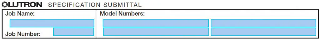
The operating voltage range for load A is 25 – 35 V at 0.5 A. Since the load specifications are within the operating range, the combination of LED load and LED driver is compatible.

Load B (Not Compatible)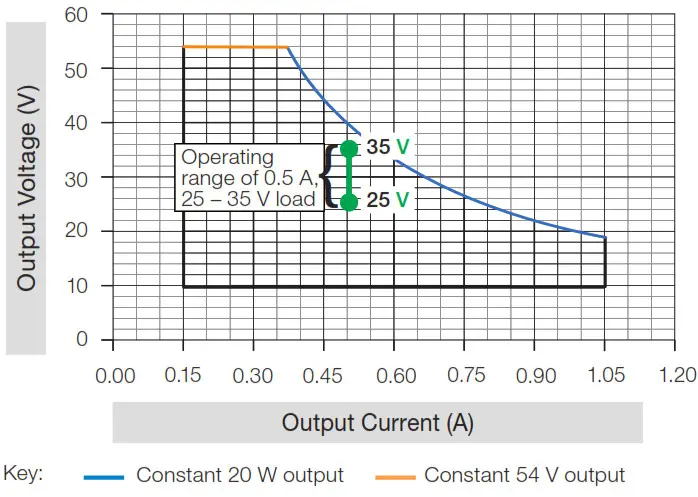
Since the maximum voltage of the load, 35 V, exceeds the 28.5 V allowable at 0.7 A, this combination of LED load and LED driver is not compatible.
Load Compatibility

4.The LED Driver Selection Tool (www.lutron.com/drivers) is a website compatibility tool that allows for a fast compatibility search of all Lutron LED drivers that are compatible with an LED load.
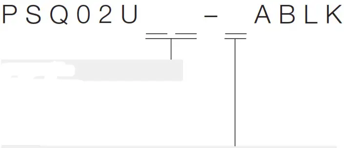
5See T-Series Model Number to create the appropriate model number for the desired driver. T-Series drivers are only available as “BLK” drivers for use with QwikFig Air.
* Lines are an example and not the range of the T-Series LED driver.
T-Series Model Number
W-case type

YS-case type
YN-case type
Case Type
• WN: W Case Type
• YS: YS Case Type
• YN: YN Case Type
LED Load Output Range: Class 2 Constant Current
(see the following pages for more detail)
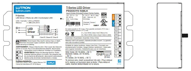
• 5: 50 W Max, 0.20 – 1.50 A, 8 – 54 V![]() *
*
* Output voltage range changes with output current and according to power limits. Check driver specifications on the following pages carefully to understand output voltage range of a particular SKU. Purchaser is responsible for electrical compatibility between LED driver and LED load.
“5” Output Range
| Driver Type | Output Voltage | Output Current | Output Power | Standards Recognition | Maximum Rated Temp. g tc for Warranty | |
| W-Case | Constant Current Driver (Class 2) | 8-54 V= | 0.20-1.50 A* | 50 W” | 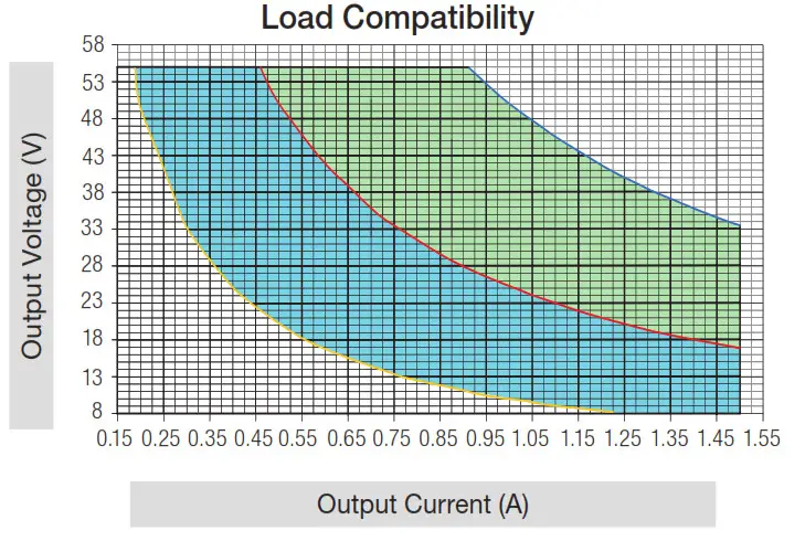 |
75 °C |
| Y-Case | Constant Current Driver (Class 2) | 8-54 V= | 0.20-1.50 A* | 50 W” | |
70 °C |
* QwikFig compatible model number PSQ02UWN-5ABLK is configurable to any current within this range in 0.005 A increments.
** Each channel is capable of delivering 50 W. The combined output of both channels must not exceed 50 W total.
Typical Performance Specifications:
| 277 | 120 V– | ||||
| Parameter | Value | Test Conditions | Value | Test Conditions | |
| Input Current | 0.25 A | 0.5 A | |||
| Power Factor (PF) | 0.95 | 0.99 | |||
| W-Case | Total Harmonic | 7% | 6% | ||
| Distortion (THD) | V; = 277 | V; = 120 | |||
| Driver Efficiency | 87% | ta = 25 °C la = 0.90 A | 87% | ta = 25 °C 10 = 0.90 A | |
| Input Current | 0.22 A | 0.48 A | |||
| Va = 54 V= | Va = 54 V= | ||||
| Power Factor | 0.96 | 0.99 | |||
| Y-Case | |||||
| THD | 9% | 9% | |||
| Driver Efficiency | 88% | 88% | |||
Please see the graphs on the following page.

Key:
Constant 25 W output
Constant 50 W output
Constant 10 W output
Shaded area meets both ENERGY STAR Luminaires V2.1 Specification and DLC Version 4.3 (W case only). Areas outside of shaded areas may not meet THD or PF requirements.
Shaded area meets only ENERGY STAR Luminaires V2.1 Specification. Areas outside of shaded areas may not meet THD or PF requirements.
Typical Power Factor vs Total Power Output
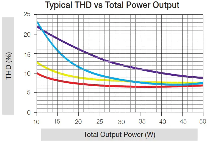
Typical THD vs Total Power Output
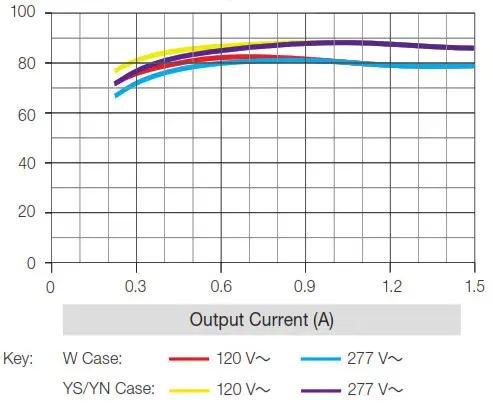
Typical Efficiency vs Output Current
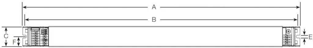
W Case Dimensions
All measurements are shown as: in (mm)
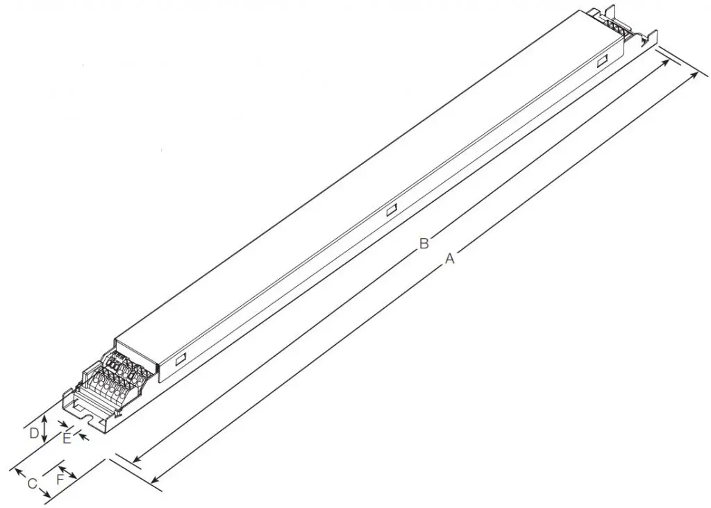
A = 16.06 (408)
B = 15.79 (401)
C = 1.18 (30)
D = 0.827 (21)
E = 0.165 (4)
F = 0.59 (15)
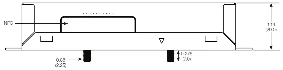
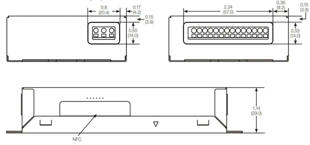
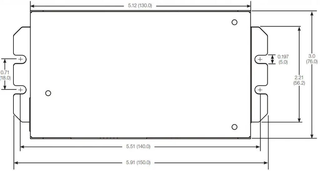
YS Case Dimensions
All measurements shown as: in (mm)
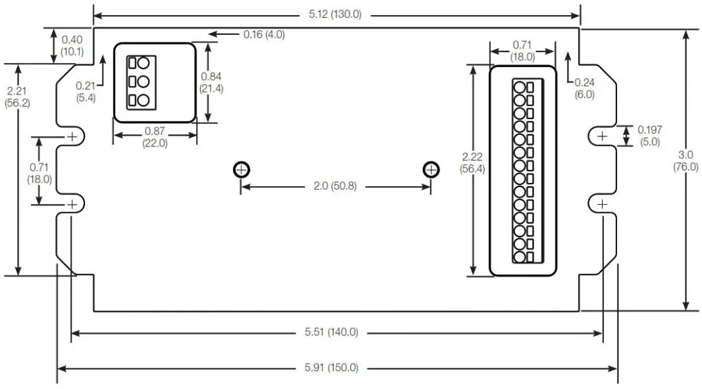
YN Case Dimensions
All measurements shown as: in (mm)
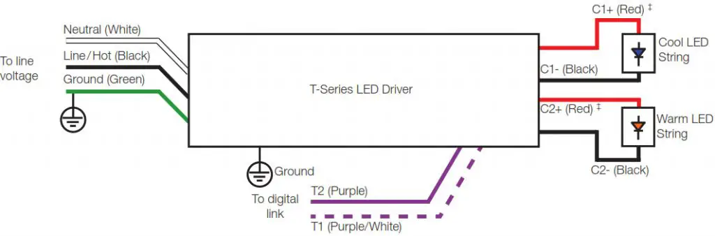
Wiring Diagram
‡C1+ and C2+ are electrically connected inside the driver. This supports the use of common anode loads.
Tunable White Considerations
- The driver will consume two digital addresses:
– Address N controls intensity*
– Address N+1 controls color temperature* - The highest kelvin light source must be connected to channel 1 (cool white).
- The lowest kelvin light source must be connected to channel 2 (warm white).
- The driver can accept LED light sources with a physical CCT value between 1500 K and 6500 K.
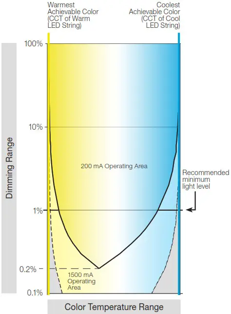
- The driver default minimum intensity level is set to 1%.
See the Tunable White Capability figure to the right for more information. - Operation below 1% may be acceptable in some applications. The minimum level can be adjusted below 1% through the Quantum software. See the Tunable White Capability figure to the right for understanding the general trade-off of dimming range versus color temperature range.
- For optimal tunable white performance, it is recommended to set high-end and low-end logical trims which reduce the overall CCT range to less than the maximum capacity of the light source.
Tunable White Capability
* This is the default behavior. During commissioning, the system may change the addresses to be non-consecutive.
Compatible Controls: Lutron T-Series Digital Controls
Guaranteed performance specifications with the controls listed in the chart below.
For assistance selecting controls, contact our LED Center of Excellence at 1.877.346.5338 or [email protected]
| Lutron T-Series Compatible Controls | Part Number | ||||
| 120 V~ | 277~ | T-Series Loops per Control |
T-Series Drivers per Loop |
Total T-Series Drivers per Control |
|
| T-Series Energi Savr Node* | QSN-TW | 2 | 32** | 64 | |
*Must be used as part of a Quantum system version 3.4 or higher.
**Each T-Series loop is capable of having 64 addresses. Each driver consumes two addresses.
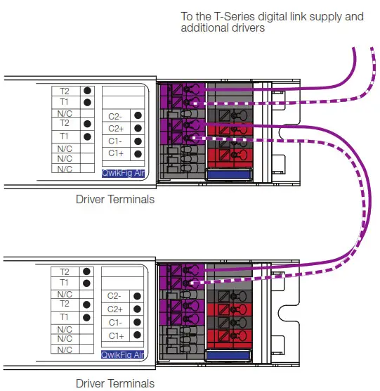
T-Series Wiring
T-Series Digital Link Overview
- The T-Series digital link wiring (T1 and T2) connects the digital ballasts and drivers together to form a lighting control system.
- T1 and T2 (T-Series digital link wires) are polarity-insensitive and can be wired in any topology (e.g., T-tap and daisy-chain).
- Power is supplied to the T-Series digital link from the control system.
T-Series Digital Link Wiring - Make sure that the supply breaker to the drivers and T-Series digital link supply is OFF when wiring.
- Connect the two conductors to the two driver terminals T1 and T2 as shown.
- Using two different colors for T1 and T2 will reduce confusion when wiring several drivers together.
- There are two sets of T-Series digital link terminal blocks to support daisy chaining the link.
- The T-Series digital link may be wired Class 1 or Class 2. Consult applicable electrical codes for proper wiring practices. Please refer to Lutron Application Note #142 (048162) at www.lutron.com for more information.
- For emergency lighting wiring, please refer to Lutron Application Note #106 (048106) at www.lutron.com

Notes
• The T-Series digital link supply does not have to be located at the end of the digital link.
• The Maximum Wire Length table below gives the limits for each of the wires in the T-Series digital link pair.
• The T-Series digital link length is limited by the wire gauge used for T1 and T2 as follows:
| Wire Gauge | Maximum Wire Length |
| 12 AWG | 1000 ft |
| 14 AWG | 1000 ft |
| 16 AWG | 900 ft |
| 18 AWG | 550 ft |
| Wire Size | Maximum Wire Length |
| 4.0 mm2 | 300 m * |
| 2.5 mm2 | 300 m * |
| 1.5 mm2 | 300 m |
| 1.0 mm2 | 207 m |
| 0.75 mm2 | 155 m |
Service
Warranty
For warranty information, please visit 3601281_ENG_Web [PDF]
Replacement Parts
When ordering Lutron replacement parts, please provide the full model number. Consult Lutron if you have any questions.
Further Information
For further information, please visit us at
www.lutron.com or contact our LED Control Center of
Excellence at 1.877.346.5338 or [email protected]
 Lutron, Lutron, Energi Savr Node, Quantum, QwikFig, and QwikFig Air are trademarks or registered trademarks of Lutron Electronics Co., Inc. registered in the U.S. and other countries.
All product names, logos, and brands are the property of their respective owners.