LUTRON QSW-DMX-IN Software License Instructions
DMX Input Software License for Quantum
This license for DMX input software allows a DMX lighting stage board (or other DMX source) to controlthe levels of lights that are part of a Quantum Total Light Management system. Users continue to experience the benefits of Quantum Total Light Management (e.g., scheduled events, occupancy sensing, daylighting, wall-station control) while also maintaining flexible DMX control for setting up light levels during special events.This feature is intended for flexible, static lighting zone adjustment; it is not intended to manage continuously changing light levels (e.g., theatrical lighting.
Model Number
QSW-DMX-IN
Features
- Supports up to 512 input channels per processor on a single universe.
- An input channel controls a single lighting zone in the system.
- DMX input control can be enabled and disabled on an area-by-area basis.
- Enabling and disabling DMX is achieved by activating or deactivating the DMX scene in an area.
- Enabling and disabling the DMX scene in an area can be activated through a timeclock event, contact closure input, or keypad button press.
- DMX control must be enabled by activating the specified DMX scene before DMX zone control can take place in that area. This can be accomplished via contact-closure input, wall station, keyswitch control, Quantum Vue or other programmable input.
- Supports zone chaining for partitioned spaces.
- Supports a sustained rate of up to five constantly changing channels at any one time.
Capabilities
- Adjusts a given zone level up to 10 times / second in response to DMX input.
- Supports a burst rate of up to 500 zone level adjustments / second for a maximum of 10 seconds.
- Each input channel can control a single lighting zone (dimmed or non-dimmed)
Requirements
- Requires a dedicated link on a Quantum processor that will be controlling zones using a DMX input. – Only one link per processor can be dedicated for DMX, with a maximum of 512 inputs on this link. – Each input can be mapped to only one zone. The zone must be in the same logical processor subsystem as the DMX input that is controlling it.
- When controlling the zones in an area from another source (e.g., a wall station, scheduled event, Quantum Vue software), the zones in that area will exit the DMX scene. To prevent this from happening, these sources must be locked or disabled.
- The lights in an area will not respond to DMXcommands unless the DMX scene is active in that area.
- One license is required for each processor. The license is only required for processors that manage the zones being controlled via a DMX input.
- This license must be activated by Lutron Field Service.
- Requires Quantum version 3.1 or higher.
Limitations
- If daylighting is enabled on all scenes in an area, the DMX scene will also be daylighted
- DMX inputs cannot be mapped to 3-channel DMX zones or to a GRAFIK Eye QS zone.
- The DMX input control is only compatible with the following Lutron lighting controllers:
- GP dimming panels
- LP dimming panels
- CCP dimming panels
- XP switching panels
- Energi Savr Node 0–10 V- modules
- Energi Savr Node switching modules
- Energi Savr Node phase-adaptive modules
- EcoSystem devices connected directly to QP2 hubs
Note: DALI devices, EcoSystem devices connected to a GRAFIK Eye QS unit, and Eco System devices connected to an Energi Savr Node with EcoSystem unit cannot be controlled via the DMX input control feature.
Best Practices
• See Application Note #592 Lutron Solutions for DMX512-A (www.lutron.com/TechnicalDocumentLibrary/048592.pdf)
SPECIFICATION SUBMITTAL
| Job Name:__________________ | Job Name:_________ |
| Job Name:_______________ | ________________ _________________ |
Wiring
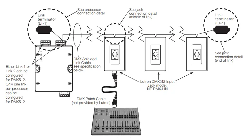
DMX512 Input Typical 1-Line Diagram

Note: If connecting more than one jack to the processor, only one DMX512 lighting control console can be connected to a link at the same time. If multiple consoles need to be connected at the same time, a merger should be used.
See Application Note # 592 (P/N 048592) for more information.
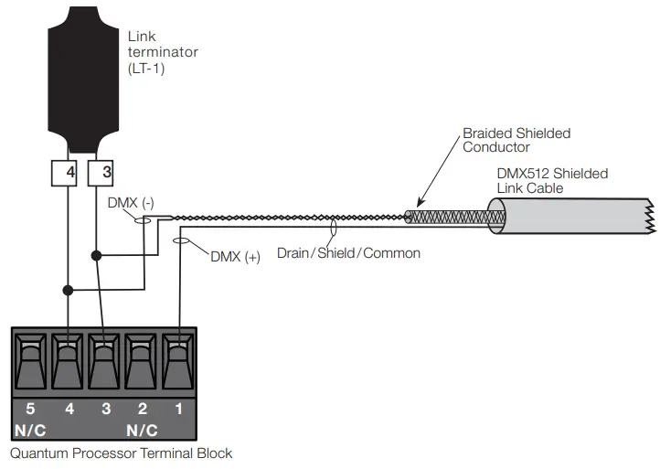
DMX512 Quantum Processor Connection Details
Wiring
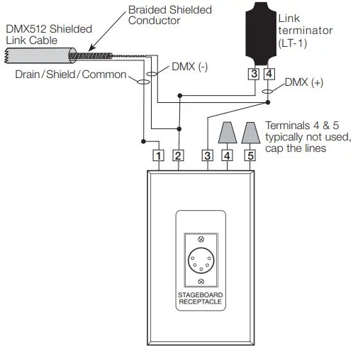
Jack Connection Detail (End of Link)
Jack Connection Detail (Middle of Link)
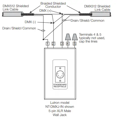
DMX XLR Jack Pinout Standard
- Drain/Shield/Common
- DMX (-) Primary Link
- DMX (+) Primary Link
- DMX (-) Secondary Link
- DMX (+) Secondary Link
DMX Cable Wiring Table
The table below provides information pertaining to Lutron-provided (optional) DMX cable and how it should be terminated. For third-party cable, consult with the manufacturer for their connection recommendations and always use shielded cable that complies with the ANSI E1.11-2008, USITT DMX512-A standard.
| Manufacturer | Model | Signal Name | Wire Color | Lutron model NT-DMXJ-IN connection | Lutron Quantum Procesor Connection |
| Lutron | GRX-CBL-DMX-250 or GRX-CBL-DMX-500 | Drain / Shield / Common | Use braided wire that surrounds the twisted pairs | Pin 1 – Drain / Shield / Common (white with black stripe) | Pin 1 – Common |
| DMX (-) Primary Link | White or pink | Pin 2 – DMX (-) Primary Link (red) | Pin 4 – _ | ||
| DMX (+) Primary Link | Black | Pin 3 – DMX (+) Primary Link (yellow) | Pin 3 – MUX | ||
| DMX (-) Secondary Link | Green | Pin 4 – DMX (-) Secondary Link (blue) | No connection (cap the wire) | ||
| DMX (+) Secondary Link | Red | Pin 5 – DMX (+) Secondary Link (black) | No connection (cap the wire) |