Vive Hub
Installation Instructions
Please Read Before Installing

P/N 041744
Rev B
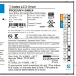
Power Supply (PS-J-20W-UNV):
Input: 120–277 V~ 50 / 60 Hz 0.6 A
Output: 24 V- 830 mA
Vive Hub (HJS-): 24-36 V- 350 mA
| Model Numbers | Description |
| HJS-0-FM | Starter hub, flush-mount adapter and power supply |
| HJS-1-FM | Vive hub, flush-mount adapter, and power supply |
| HJS-1-SM | Vive hub, surface-mount adapter and power supply |
| HJS-2-FM | Premium Vive hub, flush-mount adapter and power supply |
| HJS-2-SM | Premium Vive hub, surface-mount adapter and power supply |
| Replacement Parts | Description |
| PS-J-20W-UNV | Vive hub external power supply |
| H-MOUNT-FM | Flush-mount installation bracket |
| H-MOUNT-SM | Surface-mount installation bracket |
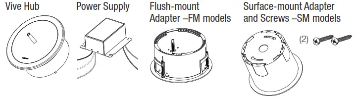
Included Components
Important Notes
General
- For installation by a qualified electrician in accordance with all local and national electrical codes.
- In Canada, separate over-current protection is required to be in accordance with the Canadian
Electrical Code, Part 1. - The primary branch circuit must be protected by a 15 A or 20 A breaker (as applicable).
- The primary wiring must be 18 AWG to 14 AWG (1.0 mm2 to 2.5 mm2) and rated for at least 167 ˚F (75 ˚C).
- If moisture or condensation is evident, allow the product to dry completely before installation.
- Operate between 32 °F and 104 °F (0 °C and 40 °C).
- 0% to 90% humidity, non-condensing.
- For indoor use only.
Vive Hub
- Clean the Vive hub with a soft damp cloth only. DO NOT use any chemical cleaners.
- DO NOT paint the Vive hub.
- The Vive hub is part of a system and cannot be used to control a load without a compatible system device. Please refer to the system device(s) instruction sheet or www.lutron.com for installation information.
- Up to 700 Lutron wireless devices can be associated with the Vive hub.
- Installation near metal, other than a junction box, may reduce RF range. The Vive hub should be at least 12 in (305 mm) away from metal objects.
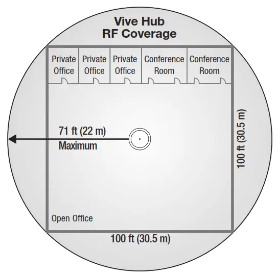
- All wireless devices must be within 71 ft (22 m) of the Vive hub. This range applies to both Clear Connect devices and Wi-Fi.
- A corporate Wi-Fi network can interfere with the Wi-Fi on the Vive hub. Where a corporate Wi-Fi network exists, it is recommended to connect the Vive hub to the corporate network using the Ethernet connection on the hub and disable the hub’s Wi-Fi.
- Must be mounted a minimum of 10 ft (3 m) from Wi-Fi router.
- For a secure way to de-commission the Vive hub, please contact Lutron Customer Assistance.
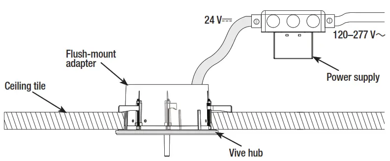
Typical Application
Instructions
Product Overview
(Flush-mount Adapter shown)
Installation
Turn OFF power at circuit breaker.
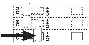
 WARNING! Shock Hazard. May result in serious injury or death. Turn off power at circuit breaker before installing the unit.
Installing the Mounting Adapter
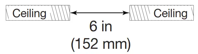
The Vive hub can be mounted on a variety of ceiling materials (thickness ranging from 1/4 in to 11⁄4 in (6 mm to 32 mm) with the mounting bracket provided.
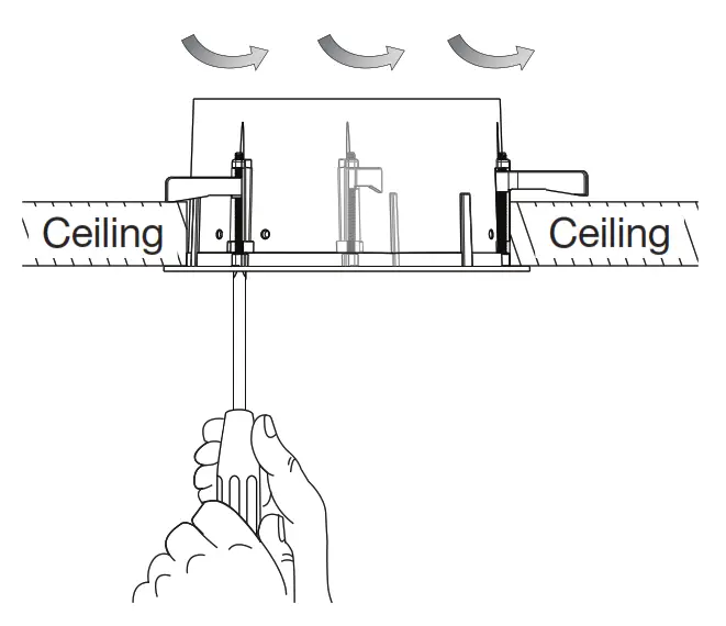
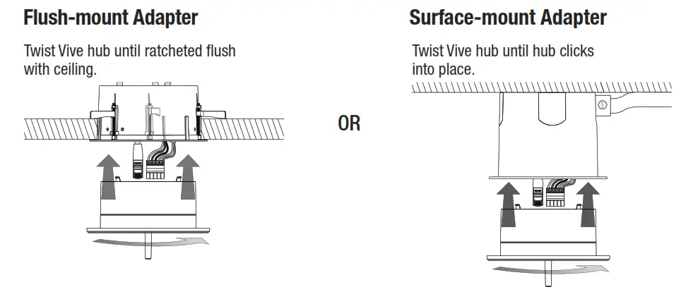
Flush-Mount adapter
A. Cut a 6 in (152 mm) diameter mounting hole in the ceiling to insert the mounting bracket.
B. Insert the flush-mount Adapter into the hole and rotate the three brackets outwards by turning screws.
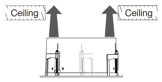
C. Using a Phillips head screwdriver, hand-tighten the brackets, clamping the adapter to the ceiling. DO NOT overtighten.
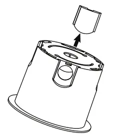
Surface-Mount adapter
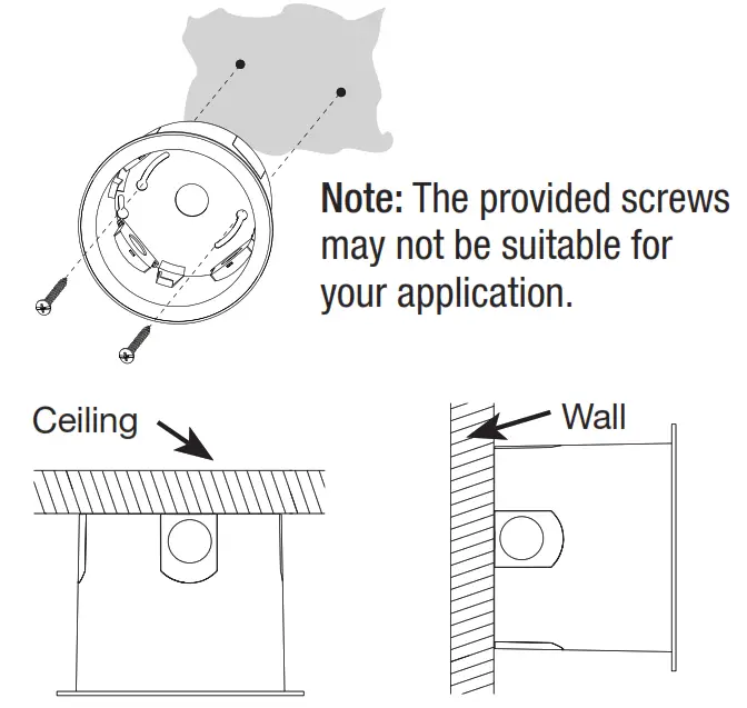
A. 1. Remove installed doors to access the optional conduit knockouts. The knockouts provide a connection point for 1/2` in or 3/4 in (13 mm or 19 mm) conduit.
2. Attach the surface-mount adapter to the wall or ceiling using the included screws or appropriate screws that will securely mount the device.
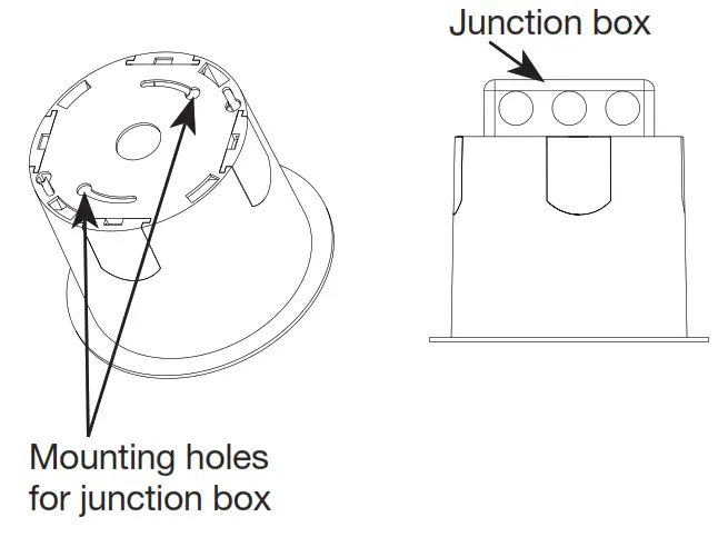
B. Alternate installation methods: Attach the surface-mount adapter to a junction box (4 in x 4 in (102 mm x 102 mm) square or 4 in(102 mm) octagonal).
Wiring
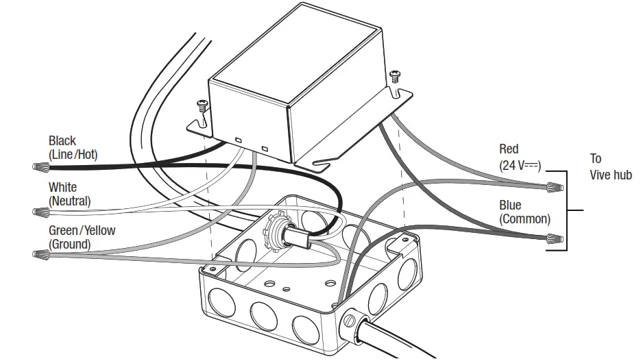
A. Power Supply
- Ground the junction box in accordance with NEC® / local codes.
- Mount the power supply to the junction box. The power supply must be mounted within 100 ft (30 mm) of the Vive hub.
- Make wiring connections as shown.
Note: DO NOT power the Vive hub with an Uninterruptable Power Supply (UPS) or emergency generator power. The Vive hub must be powered with normal power only when emergency PowPak /Fixture Controllers are utilized in the system. If the Vive hub is powered from UPS or emergency generator power any emergency PowPak utilized in the system will either not enter emergency mode, or exit emergency mode prematurely.
Note: Maintain separation of the power supply Class 2 output wiring from all other conductors by a minimum of 1/4 in (6.4 mm) or by a non-conductive sleeve or non-conductive barrier.
B. Vive Hub
- Run the low-voltage wiring from the power supply to the Vive hub. Most applications will require an additional length of wire to connect the junction box with the Vive hub. Wiring should be 24 AWG–12 AWG (0.2 mm 2–2.5 mm 2).
- Wire the Vive hub terminal block. Contact Closure Input 1 (CCI1) is programmed by default to meet Title 24 Automatic Demand Response (where applicable). Closing this input will shed the lighting load by 20% for connected Vive compatible lighting devices. Contact Closure Input 2 (CCI2) is programmed by default to have no effect. CCI2 can be configured during programming.
Note: Terminal blocks are removable for ease of wiring.
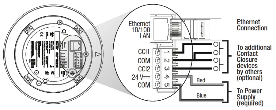
3. Connect the Ethernet cable to connect to Building Management Systems, wired networks, and other Vive hubs.
Attaching the Vive Hub to the Adapter
Note: Prior to installing the hub, record the Wi-Fi SSID printed on the label. Attach the Vive hub into the ceiling-mount adapter by inserting and twisting in a clockwise direction until the hub locks into place.
Turn ON power at circuit breaker.
Programming
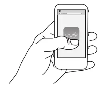
The Vive hub can be set-up easily with any Wi-Fi enabled iOS® or Android® compatible device.
a. Download the Lutron Vive app.

b. Open the app and follow the instructions.
| LED Feedback | |
| Mode / Error | LED Pattern Description |
| Normal Operation | Blink White once every 10 seconds |
| Software update | Blink alternately between Blue and White |
| Reset to factory defaults | Blink alternately between Green and Amber |
| Recovery | Solid Blue |
| Troubleshooting | www.lutron.com/vive |
| Symptom | Possible Solutions |
| Forgot password | • Hold the button on the back of the Vive hub for 30 seconds or until the LED flashes white. |
| Cannot connect over Wi-Fi | • Move closer to the Vive hub. • Verify that the power is connected to the hub. • Check Wi-Fi settings on the smart device. • Connect over the Ethernet and verify that the Wi-Fi is enabled on the hub (see Wi-Fi settings). |
| Cannot connect over Ethernet | • Verify that the power is connected to the Vive hub. • Verify that the wired Ethernet is connected properly. • Verify that the Ethernet cable is less than 328 ft (100 m) in length. |
| LED is Off | • Verify that the power is connected to the Vive hub. • LED should blink once every 10 seconds if the Vive hub is powered properly. |
| LED is red | • Contact Lutron only if maintained more than 30 seconds or occurs periodically. |
| LED is blue | • Contact Lutron. |
| External events (such as Automatic Demand Response) are not triggering | • Verify the contact closure input 1 is connected. • Check the programming for contact closure inputs. |
Customer Assistance:
U.S.A. / Canada / Caribbean: 1.844.LUTRON1
Mexico: +1.888.235.2910
Others: +1.610.282.3800
www.lutron.com/support
Limited Warranty: warranty [PDF]
For FCC/IC information: Please visit: Lutron FCC ID Filings

Lutron Electronics Co., Inc.
7200 Suter Road
Coopersburg, PA 18036-1299 USA
Lutron, Clear Connect, PowPak, and Vive are trademarks or registered trademarks of Lutron Electronics Co., Inc. in the US and/or other countries. Safari is a trademark of Apple Inc., registered in the U.S. and other countries. All other product names, logos, and brands are property of their respective owners.
© 2015-2021 Lutron Electronics Co., Inc.