Introduction
Congratulations on the purchase of your new appliance. You have selected a high-quality product. The operating instructions are part of this product. They contain important information about safety, usage and disposal. Before using the product, please familiarise yourself with all operating and safety instructions. Use the product only as described and for the range of applications specified. Please also pass these operating instructions on to any future owner
Intended use
This appliance is designed for painting indoor walls as well as outdoor objects. Permissible materials for use include: – water-based paints and varnishes
Do not use for:
- Flammable coatings, materials containing acetone or nitro thinners,
- Materials that contain highly abrasive components,
- Facade paint, lyes and acidic coating materials. Do not use the appliance in areas where there is a risk of explosion. Any other usage or modification of the appliance is deemed to be improper and carries a significant risk of accidents. The manufacturer accepts no responsibility for damage(s) resulting from improper usage. This appliance is intended for domestic use only.
Equipment
- Return hose
- Suction hose
- Pressure regulator dial
- Storage compartment for nozzles and HEA filters
- Nozzle
- Safety catch
- Paint spray gun
- Handle
- Trigger
- Connecting thread for paint spray gun
- HEA filter
- High-pressure hose
- Function switch
- Connecting thread
- Intake filter
- Valve trigger
- Filter plate
- Plastic ring
- Holder
- Nozzle chamber
- Nozzle holder
- Spring
- Washer
- Ball
- O-ring
- Inlet valve
- Fastening screw
- Hex screw
- Hose clips

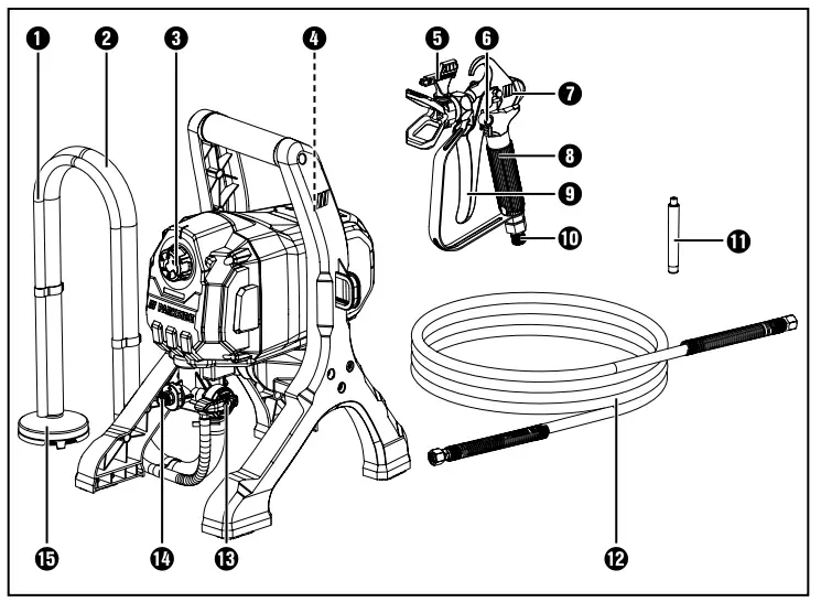
Package contents
- 1 airless paint sprayer
- 1 paint spray gun
- 1 intake hose, 1 m, (pre-fitted) including return hose
- 1 high-pressure hose, 9 m
- 1 white HEA filter (pre-fitted)
- 1 yellow HEA filter
- 2 nozzles 311 and 517* (*pre-fitted)
- 1 set of operating instructions
Technical specifications
Motor unit
- Rated voltage 230 V ∼, 50 Hz (AC)
- Rated power consumption 550 W
- Max. paint flow rate 1250 ml/min
- Max. working pressure 110 bar
- Max. temperature of coating material 40°C
- Protection class : I
- Protection rating IPX3 Protection against water spray, up to 60° compared to normal operating position
Paint spray gun
- Max. surface temperature 43°C
- Max. temperature of coating material 40°C
Noise and vibration data
Noise measurement value determined in accordance with EN 62841. The A-rated noise level of the power tool is typically
- Sound pressure level LpA = 88 dB (A)
- Uncertainty K = 3 dB
- Sound power level LWA = 101 dB (A)
- Uncertainty K = 3 dB
Noise measurement value determined in accordance with EN 14462. The rated noise level of the paint spray gun is typically:
- Sound pressure level LpA = 78.4 dB
- Uncertainty K = 2.5 dB (A)
- Sound power level LWA = 91.2 dB
- Uncertainty K = 2.5 dB (A)
Wear ear muffs!
Total vibration value of the
- handle ah < 5.1 m/s2
- Uncertainty K = 1.5 m/s2
Symbols on the appliance

NOTE
- The vibration emission values and the noise emission values given in these instructions have been measured in accordance with a standardised test procedure and can be used for comparison of the power tool with another tool.
- The specified total vibration values and the noise emission values can also be used to make a provisional load estimate.
WARNING
- Depending on the manner in which the power tool is being used, and in particular the kind of workpiece being worked, the vibration and noise emission values can deviate from the values given in these instructions during actual use of the power tool.
- Try to keep the vibration load as low as possible. Measures to reduce the vibration load are, e.g. wearing gloves and limiting the working time. Wherein all states of operation must be included (e.g. times when the power tool is switched off and times where the power tool is switched on but running without load).
General power tool safety warnings
WARNING
Read all safety warnings, instructions, illustrations and specifications provided with this power tool. Failure to follow all instructions listed below may result in electric shock, fire and/or serious injury.
Save all warnings and instructions for future reference.
The term “power tool” in the warnings refers to your mains-operated (corded) power tool or battery operated (cordless) power too
Work area safety
- Keep work area clean and well lit. Cluttered or dark areas invite accidents.
- Do not operate power tools in explosive atmospheres, such as in the presence of flammable liquids, gases or dust. Power tools create sparks which may ignite the dust or fumes.
- Keep children and bystanders away while operating a power tool. Distractions can cause you to lose control.
Electrical safety
- Power tool plugs must match the outlet. Never modify the plug in any way. Do not use any adapter plugs with earthed (grounded) power tools. Unmodified plugs and matching outlets will reduce risk of electric shock.
- Avoid body contact with earthed or grounded surfaces, such as pipes, radiators, ranges and refrigerators. There is an increased risk of electric shock if your body is earthed or grounded.
- Do not expose power tools to rain or wet conditions. Water entering a power tool will increase the risk of electric shock.
- Do not abuse the cord. Never use the cord for carrying, pulling or unplugging the power tool. Keep cord away from heat, oil, sharp edges or moving parts. Damaged or entangled cords increase the risk of electric shock.
- When working outdoors with an electrical power tool always use extension cords that are also suitable for use outdoors. Use of a cord suitable for outdoor use reduces the risk of electric shock.
- If operating a power tool in a damp location is unavoidable, use a residual current device (RCD) protected supply. Use of an RCD reduces the risk of electric shock.
Personal safety
- Stay alert, watch what you are doing and use common sense when operating a power tool. Do not use a power tool while you are tired or under the influence of drugs, alcohol or medication. A moment of inattention while operating a power tool may result in serious personal injury.
- Use personal protective equipment. Always wear safety goggles. Protective equipment such as a dust mask, non-skid safety shoes, hard hat or hearing protection used for appropriate conditions will reduce personal injuries.
- Prevent unintentional starting. Ensure the switch is in the off-position before connecting to power source and/or battery pack, picking up or carrying the tool. Carrying power tools with your finger on the switch or energising power tools that have the switch on invites accidents.
- Remove any adjusting key or wrench before turning the power tool on. A wrench or a key left attached to a rotating part of the power tool may result in personal injury.
- Do not overreach. Keep proper footing and balance at all times. This enables better control of the power tool in unexpected situations.
- Dress properly. Do not wear loose clothing or jewellery. Keep your hair and clothing away from moving parts. Loose clothes, jewellery or long hair can be caught in moving parts.
- If devices are provided for the connection of dust extraction and collection facilities, ensure these are connected and properly used. Use of dust collection can reduce dust-related hazards.
- Do not allow yourself to get lulled into a false sense of security and do not ignore the safety regulations for power tools, even if you are familiar with the power tool after repeated use. A careless action can cause severe injury within a fraction of a second.
Power tool use and care
- Do not force the power tool. Use the correct power tool for your application. The correct power tool will do the job better and safer at the rate for which it was designed.
- Do not use the power tool if the switch does not turn it on and off. Any power tool that cannot be controlled with the switch is dangerous and must be repaired.
- Disconnect the plug from the power source and/or remove the battery pack, if detachable, from the power tool before making any adjustments, changing accessories, or storing power tools. Such preventive safety measures reduce the risk of starting the power tool accidentally.
- Store idle power tools out of the reach of children and do not allow persons unfamiliar with the power tool or these instructions to operate the power tool. Power tools are dangerous in the hands of untrained users.
- Maintain power tools and accessories. Check for misalignment or binding of moving parts, breakage of parts and any other condition that may affect the power tool’s operation. If damaged, have the power tool repaired before use. Many accidents are caused by poorly maintained power tools.
- Keep cutting tools sharp and clean. Properly maintained cutting tools with sharp cutting edges are less likely to bind and are easier to control.
- Use the power tool, accessories and tool bits, etc. in accordance with these instructions, taking into account the working conditions and the work to be performed. Use of the power tool for operations different from those intended could result in a hazardous situation.
- Keep handles and grasping surfaces dry, clean and free from oil and grease. Slippery handles and grasping surfaces do not allow for safe handling and control of the tool in unexpected situations.
Service
- Have your power tool serviced by a qualified repair person using only identical replacement parts. This will ensure that the safety of the power tool is maintained.
Additional safety instructions
RISK OF EXPLOSION AND FIRE!
Make sure there are no ignition sources in the vicinity. There is a risk of explosion due to the potential formation of an explosive atmosphere in combination with ignition sources (e.g. by electrostatic discharge, electric sparks, hot surfaces)!
- RISK OF INJURY! DUE TO MISUSE! Do not
point the appliance towards people or animals. - RISK OF EXPLOSION/FIRE! SMOKING PROHIBITED! Do not cause any sparks or ignite a naked flame. Make sure there are no ignition sources in the vicinity, such as open fires, smoking cigarettes, cigars and tobacco pipes, sparks, glowing wires, hot surfaces, etc.RISK OF INJURY! DUE TO MISUSE! Do not point the appliance towards people or animals.
- RISK OF EXPLOSION/FIRE! SMOKING PROHIBITED! Do not cause any sparks or ignite a naked flame. Make sure there are no ignition sources in the vicinity, such as open fires, smoking cigarettes, cigars and tobacco pipes, sparks, glowing wires, hot surfaces, etc.
WARNING
Keep your distance from the nozzle tip!
- Do not spray yourself, other people or animals. Keep your hands and other body parts out of the spray jet. If the spray jet pierces your skin, seek medical assistance immediately. The sprayed material can even penetrate through a glove and into the skin and thus into your body.
- Do not treat an injection wound as a simple cut. A high-pressure jet can inject toxins into the body and cause serious injuries (e.g. necrosis, loss of limbs). In the event of a chemical penetration of the skin, seek medical assistance immediately.
- Before each use, the following points must be observed in accordance with the operating instructions:
- Do not use an appliance if it is faulty.
- Secure the hand spray gun against accidental activation using the safety catch on the trigger.
- Ensure earthing – The connection must be made via a properly earthed safety socket (Schuko).
- Check the maximum permissible operating pressure of the high-pressure hose and spray gun.
- Check all connections for leaks
- Strictly follow the instructions on regular cleaning and maintenance of the appliance. Observe the following rules before carrying out any work on the appliance and at every work break:
- Depressurise the spray gun and the high-pressure hose.
- Secure the hand spray gun against accidental activation using the safety catch on the trigger.
- Switch off the appliance.
- Do not use the appliance in areas that fall under the explosion protection ordinance.
- Keep your work area clean, well lit and free of paint and solvent containers, cloths and other inflammable materials. Possible risk of spontaneous combustion. Make sure you have functional fire extinguishers available at all times.
- Do not spray or clean with materials whose ignition point is lower than 21°C. Use waterbased materials, non volatile hydrocarbons or similar materials. The evaporation of volatile solvents will cause an explosive environment.
- Do not spray near ignition sources such as static electric sparks, open flames, ignition flames, hot items, motors, cigarettes or sparks caused by plugging in/unplugging power cables or by operating switches. These kinds of ignition sources could ignite a fire in the environment.
- Do not spray any material if you do not know whether it is potentially dangerous. Unknown materials can cause hazards.
- To avoid potential risks, damaged mains cables should be replaced by the manufacturer, their customer service department or someone similarly qualified.
- Wear additional personal protective equipment such as suitable gloves and a protective mask/respirator when spraying or when handling chemicals. Wearing appropriate protective equipment for the conditions reduces your exposure to dangerous substances.
- Be aware of the potential hazards of the sprayed material. Follow the markings on the container and the manufacturer’s information on the spray material you are using, including the instructions to use personal protective equipment. Follow the manufacturer’s instructions to reduce the risk of fire and injuries caused by poisons, carcinogens, etc.
- The spray gun must not be used for spraying flammable substances. Do not clean spray guns with flammable solvents.
- Secure the appliance and the spray gun.
- Secure all hoses, connections and filter parts before starting up the spray pump. Unsecured parts can come loose with great force or fluid can escape at high pressure, causing serious injury. Always secure the spray gun when assembling or disassembling the nozzle and during any breaks in work.
- Be prepared for recoil from the spray gun during operation. At high operating pressure, pulling the trigger causes a recoil force of up to 15 N. If you are not prepared for this, your hand may be pushed back or you may lose your balance. This can lead to injuries. Continuous exposure to this recoil can lead to permanent damage to health.
- Max. operating pressure: the permissible operating pressure for the spray gun, high-pressure hose and spray gun accessories must not be less than the maximum operating pressure of 110 bar (11 MPa) indicated on the appliance.
- The appliance must be connected via a properly earthed safety socket (Schuko). The connection must be equipped with a residual current device INF ≤ 30 mA.
- Make sure that the mains supply being connected corresponds to the values indicated on the type plate.
- Before carrying out any work on the appliance, relieve the pressure and disconnect the mains plug from the socket.
- You must earth the object that you are intending to spray!
- Observe the user manual when installing, maintaining and repairing the appliance.
- The appliance must be earthed during installation.
- Ensure adequate ventilation in the spray area and sufficient fresh air in the entire room. Wear a mask!
- Always wear suitable safety goggles to keep hazardous vapours and liquids away from your eyes.
- Wear protective clothing to keep paint away
from your skin and hair.
WARNING
- Under certain circumstances, the flow rate of the coating material may cause electrostatic charges to occur on the appliance during spraying. They can cause sparks or flames when discharged. Therefore, make sure that the appliance is always earthed via the electrical installation. The connection must be made via a properly earthed safety socket (Schuko).
- Pay attention to the hazards that may be caused by the sprayed substance and also observe the labels on the containers or the instructions given by the manufacturer of the substance.
- When working indoors: Ensure that no vapours containing solvents form in the area around the appliance. Place the appliance on the side facing away from the spray object. Keep a minimum distance of 5 m between the motor unit and the spray gun.
- When working outdoors: Do not allow vapours containing solvents to drift towards the appliance. Pay attention to the wind direction! Position the appliance so that no vapours containing solvents can reach and build up around the appliance. Keep a minimum distance of 5 m between the appliance and the spray gun.
- There is a risk of a short-circuit if water penetrates the appliance! Never clean the appliance with a high-pressure or steam cleaner.
- Do not use a solvent container with a small opening to clean the appliance. An explosive atmosphere could form. Earth the container beforehand.
Safety instructions for the highpressure hose
DANGER
- Caution: Risk of injury from injection! Leaks can develop in the high-pressure hose due to wear, kinking and improper use. Fluid from the leak can be injected into the skin.
- The electrostatic charge from the spray gun and high-pressure hose is discharged via the high-pressure hose.
- Check the high-pressure hose thoroughly before each use.
- Never pull on the high-pressure hose to move the appliance.
- Never try to repair a defective high-pressure hose yourself!
- Replace a damaged high-pressure hose immediately.
- Avoid sharp bending or kinking; the smallest bending radius is about 20 cm.
- Protect the high-pressure hose from sharp objects and edges.
- Never twist the high-pressure hose.
- Do not immerse the high-pressure hose in solvent. Wipe the outside only with a soaked cloth.
- Route the high-pressure hose so that there is no risk of tripping.
- Do not drive over the high-pressure hose.
NOTE
The risk of damage increases with old highpressure hoses. We recommend replacing the high-pressure hose every 6 years.
Original accessories/attachments
WARNING
Do not use any accessories that are not recommended by PARKSIDE. You can order spare parts and accessories from the telephone numbers given in the section “Service”.
RESIDUAL RISKS!
When using the tool, additional residual risks may occur that are not listed in the enclosed safety instructions. These risks can arise from misuse, prolonged use, etc.
Even if you follow the relevant safety regulations and use safety equipment, certain residual risks cannot be avoided.
These include:
- Lung damage, if no suitable breathing protection is worn;
- Hearing damage, if hearing protection is not worn;
- Eye damage, if suitable eye protection is not worn;
- Damage to health due to swinging of your hands and arms during prolonged operation of the appliance or if the appliance is not properly held or maintained. If you use an appliance for a long period of time, take regular breaks.
WARNING! HAZARDS CAUSED BY MATERIALS AND SUBSTANCES!
- There is a risk of coming into contact with or absorbing coating materials and/or cleaning fluids. There is also a risk of inhaling vapours from liquids. This can cause permanent damage under certain conditions.
- Always wear personal protective equipment when working on the appliance!
- Ensure sufficient technical or natural ventilation.
- Follow the manufacturers’ safety instructions for the respective coating materials and cleaning liquids.
- If you experience any symptoms, seek medical advice!
Working procedures
NOTE
- Ensure that the spray material and thinning agent are compatible. Using an unsuitable thinning agent may cause clots that clog the appliance.
- To find out which thinning agent is suitable for your spray material (water, paint thinner), refer to the manufacturer’s notes provided with the spray material.
- Granular products and products containing solids must not be sprayed. Their abrasive effect will shorten the service life of the appliance.
Preparing the spray surface
WARNING
Risk of electric shock due to penetrating spray material! Be sure to mask any sockets and switches
- Cover any surfaces around the spray area extensively and thoroughly. Any surface that is not masked could become contaminated.
- Make sure that the spray surface is clean, dry and free of grease.
- Polished surfaces should be lightly sanded and the sanding dust removed.
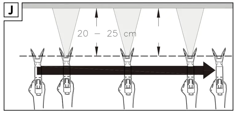
Spraying technique
- Always hold the paint spray gun at the same distance and at a right angle to the object. The ideal spraying distance is approx. 20–25 cm. Move the paint spray gun evenly with your whole arm (see fig. J).
- Determine the appropriate settings in each case by experimenting, e.g. on a piece of cardboard.
- Do not switch the appliance on/off above the spray area, but start and stop the spraying process approx. 10 cm outside the spray area.
Before use
Assembly
NOTE
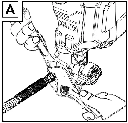
- You can assemble the appliance using two adjustable spanners (not supplied).
- Alternatively, you can also use a 16 mm and 19 mm wrench (not supplied).
- Fit the high-pressure hose w onto the connecting thread r on the appliance. Tighten the nut using an adjustable spanner. Counter the nut of the connection thread r with a second adjustable spanner (see fig. A).
- Fit the other end of the high-pressure hose w to the connecting thread of the paint spray gun 0. Tighten the nut using an adjustable spanner. Counter the nut of the connection thread of the paint spray gun with a second adjustable spanner.
- Insert the corresponding nozzle 5 with the arrow tip in the spraying direction into the nozzle chamber
Selecting/changing the nozzle
| Nozzle | Use |
| Nozzle 311 | low viscosity spray material |
| Nozzle 517 | viscous spray material |
Replacing the HEA filter
WARNING
The system must be depressurised in order to carry out the following work. To do this, follow the instructions in the section “Depressurising the appliance”.
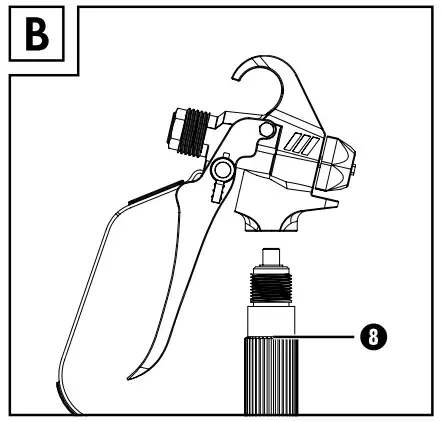
- Remove the high-pressure hose w from the paint spray gun 7.
- Turn the handle 8 clockwise until the upper end can be detached from the paint spray gun 7 (see fig. B). You can attach an adjustable spanner to the lower end of the handle to help.
- Insert the appropriate HEA filter q for the installed nozzle 5:
- white HEA filter (pre-fitted): nozzle 517
- yellow HEA filter: nozzle 311
- Turn the handle 8 anticlockwise back into the thread of the paint spray gun 7.
NOTE
Clean the HEA filters q regularly and replace them, if necessary. You can obtain replacement filters from the service hotline given in the section “Service”.
Use
- Place the suction hose 2 and return hose 1 in the paint bucket.
- Press the valve trigger z to ensure that the valve is free of any blockages.
- Insert the plug into a mains power socket.
- Turn the function switch e to the vertical position (PRIME).
- Turn the pressure regulator dial 3 to position 2 to ensure that the paint is pumped through the system.
- Wait until the paint runs through the return hose 1 back into the paint bucket. Turn the pressure regulator dial 3 to position 0 (off).
NOTE
- If no paint comes out, follow the measures described in the section “Eliminating suction problems”.
- Turn the function switch e to the horizontal position (SPRAY).
- Turn the pressure regulator dial 3 to a level corresponding to the viscosity of the sprayed material.
- Hold the paint spray gun 7 over an empty container.
- Unlock the paint spray gun 7 by turning the safety catch 6 so that its tip is facing down.
- Pull the trigger 9 until the paint comes out in a straight stream.
- Lock the paint spray gun 7 by turning the safety catch 6 with the tip as far back and up as possible
Settings
- You can use the pressure regulator dial 3 to switch the appliance on by setting a level greater than 0. The level you choose depends on the spray material used. Determine the best setting by carrying out a spray test.
- The function switch e has two settings:
- PRIME (vertical position): This setting allows you to pre-fill the system with paint or to depressurise the appliance.
- SPRAY (horizontal position): You can use this setting to work with the appliance.
Spraying
- Unlock the paint spray gun 7 by turning the safety catch 6 so that its tip is facing down.
- To spray, press the trigger 9 and hold it down.
- To stop spraying, release the trigger 9 again
WARNING
- Always secure the paint spray gun 7 while you are not actually spraying.
- Lock the paint spray gun 7 by turning the safety catch 6 with the tip as far back and up as possible.
Overheating protection
The appliance has an overheating protection. It switches the appliance off if overheating is imminent. If this happens, carry out the following steps
- Turn the pressure regulator dial 3 to position 0 (off).
- Turn the function switch e to the vertical position (PRIME).
- Let the appliance cool down for at least 30 minutes and, if necessary, remove the cause of the overheating. This could be, for example, an item that is covering the ventilation slots or if the appliance is too close to a wall.
- Put the appliance back into operation
Depressurising the appliance
Always depressurise the appliance when you want to take it out of operation. Depressurise the system as follows:
- Turn the pressure regulator dial 3 to position 0 (off).
- Turn the function switch e to the vertical position (PRIME).
- Unlock the paint spray gun 7 by turning the safety catch 6 so that its tip is facing down.
- Release the pressure by pulling the trigger 9. Hold the paint spray gun 7 over an empty container while doing so.
- Wait until all pressure and paint has been dispelled from the system. To stop spraying, release the trigger 9 again.
- Lock the paint spray gun 7 by turning the safety catch 6 with the tip as far back and up as possible.
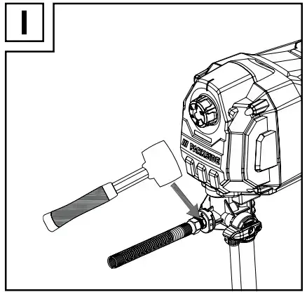
Eliminating suction problems
- Press the valve trigger z 3–4 times to remove any blockages or deposits from the valve.
- If the problem persists: tap the connecting thread r several times extremely carefully with a rubber mallet (see fig. I) to loosen harder deposits.
Blow out the nozzle
WARNING
Always secure the paint spray gun 7 while you are not actually spraying.
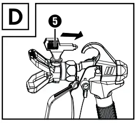
- Turn the inserted nozzle 5 180 degrees towards the rear (see fig. D). If the nozzle cannot be turned, try depressurising the appliance.
- Press the trigger 9 to blow out the nozzle 5. Hold the paint spray gun 7 over an empty container while doing so. As soon as a straight spray jet comes out, the nozzle 5 is blown out.
- Turn the inserted nozzle 5 180 degrees towards the front.
NOTE
Use an appropriate HEA filter q to minimise blockages.
Work breaks
- Depressurise the appliance.
- Turn the pressure regulator dial 3 to position 0 (off).
- Remove the plug from the mains socket.
- Place the paint spray gun 7 in a plastic bag, which you then seal airtight.
- Wet the paint in the paint bucket with water so that no skin forms on the top
Shutting down, maintenance and cleaning
ATTENTION
- Do not use flammable materials such as nitro thinners for cleaning.
- Please refer to the manufacturer’s information of the respective spray material to find out which cleaning agents are suitable
NOTE
- Thorough cleaning directly after every use is very important for safety and operation. Otherwise, the proper functioning of the appliance can no longer be guaranteed.
- Wear suitable protective gloves during cleaning work.
- Remove coating material residues at appropriate intervals. Remove any sprayed material that has got onto unwanted surfaces before it dries
- Depressurise the appliance.
- Lock the paint spray gun 7 by turning the safety catch 6 with the tip as far back and up as possible.
- Unscrew the nozzle holder a from the paint spray gun 7.
- Place the suction hose 2 together with the return hose 1 in a container with water or a suitable cleaning agent.
- Turn the function switch to the horizontal position (SPRAY).
- Turn the pressure regulator dial 3 to position 5.
- Unlock the paint spray gun 7 by turning the safety catch 6 so that its tip is facing down.
- Drain off the remaining paint by pulling the trigger 9. Hold the paint spray gun 7 over a paint bucket while doing so.
ATTENTION
If you are using a metal container, earth the paint spray gun 7 beforehand.
- Release the trigger 9 as soon as the cleaning fluid starts flowing out.
- Lock the paint spray gun 7 by turning the safety catch 6 with the tip as far back and up as possible.
- Turn the function switch e to the vertical position (PRIME).
- Unlock the paint spray gun 7 by turning the safety catch 6 so that its tip is facing down.
Drain off the remaining paint by pulling the trigger 9. Hold the paint spray gun 7 over the detergent container while doing so. - Release the trigger 9 as soon as clear cleaning fluid starts flowing out.
- Lock the paint spray gun 7 by turning the safety catch 6 with the tip as far back and up as possible.
- Turn the pressure regulator dial 3 to position 0 (off). Remove the plug from the mains socket.
- Depressurise the appliance.
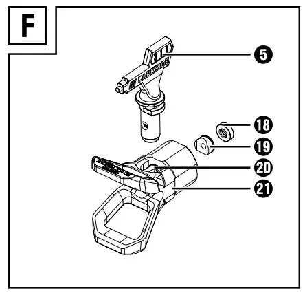
- Remove the high-pressure hose w from the paint spray gun 7 with the aid of an adjustable spanner.
- Disassemble the nozzle holder a along with the nozzle 5, holder o and plastic ring i (see fig. F). Clean all parts thoroughly using suitable cleaning agents.
- Lock the paint spray gun 7 by turning the safety catch 6 with the tip as far back and up as possible.
NOTE
Clean the HEA filters q regularly. Replace them if cleaning is no longer sufficient.
- Disconnect the suction hose 2 and the return hose 1 from the appliance using the hose clips l. Clean the outsides of the hoses.
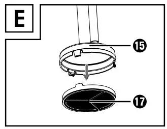
- Remove the filter plate u of the intake filter t (see fig. E).
- Clean the filter plate u thoroughly under running water.
- Remove the high-pressure hose w from the connecting thread r using an adjustable spanner. Counter the connection thread r using a second adjustable spanner.
- Dip the inlet valve h into a container filled with conservation agent (e.g. fine mechanical oil)so that the fluid can be sucked up. Insert the plug into a mains power socket.
- Hold a cloth in front of the connecting thread r. Turn the pressure regulator dial 3 to position 1 for about 5 seconds. This helps to preserve the appliance. Turn the pressure regulator dial 3 to position 0 (off).
- Remove the plug from the mains socket.
Cleaning the inlet valve
WARNING! RISK OF INJURY!
Before carrying out any work on the appliance, switch it off, disconnect the mains plug and depressurise the appliance!
NOTE
If there are irremediable problems with the paint suction, you should clean the inlet valve h or replace it, if necessary
- Disconnect the suction hose 2 from the appliance.
- Remove the inlet valve h using an adjustable spanner.
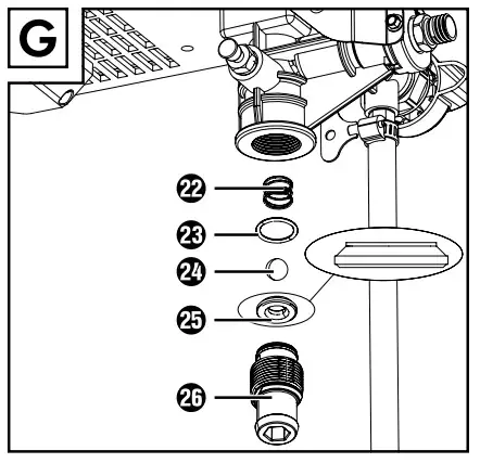
- Remove the O-ring g, ball f, washer d and spring s (see fig. G).
- Clean the parts thoroughly using suitable cleaning agents. Replace them, if necessary.
NOTE
You can obtain replacement parts not listed here from the service hotline given in the section “Service”.
- Grease the O-ring g.
- Replace the parts into the inlet valve h (see fig. G).
- Screw the inlet valve h back into the appliance. Tighten it using an adjustable spanner.
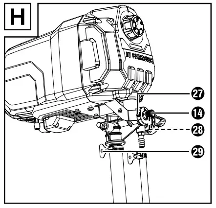
Cleaning the connecting thread
WARNING! RISK OF INJURY!
Before carrying out any work on the appliance, switch it off, disconnect the mains plug and depressurise the appliance!
If you are still experiencing a poor spray pattern after cleaning the nozzle, you should clean the connecting thread 14.
- Remove the high-pressure hose w from the connecting thread 14 using an adjustable spanner. Counter the nut of the connection thread 14 with a second adjustable spanner.
- Loosen the fastening screw 27 with a Phillips screwdriver (not supplied).
- Loosen the hex screw 28 with a 2 mm hex key (not supplied).
- Remove the connection thread 14 using an adjustable spanner.
- Clean the connecting thread 14 using a suitable cleaning agent. Replace it, if necessary.
- Screw the connecting thread 14 back into the appliance and tighten it using an adjustable spanner.
- Retighten the fastening screw 27 with a Phillips screwdriver.
- Turn the hex screw k with a 2 mm hex key.
Storage and transportation
- Store the appliance in a dry, dust-free location.
- Transport the appliance only when you have taken it completely out of service. Transport the appliance in such a way that it cannot be damaged or soiled. Preferably, use the original packaging.
Troubleshooting
| Fault | Possible cause | Remedy |
| The paint spray gun does not spray. | The inserted nozzle is clogged. | Clean the nozzle and use a suitable HEA filter. |
| The HEA filter is clogged. | Clean or replace the HEA filter. | |
| The paint spray gun is locked. | Unlock the paint spray gun. | |
| The motor is not running. | The appliance is not plugged in. | Insert the mains plug into an appropriate mains socket. |
| The appliance has overheated. | Follow the instruo lions in the section “Overheating protection”. | |
| There is no volt-age on the
mains socket. |
Check the mains socket. | |
| The appliance has been operated and main. tained according to the operating instructions, but still does not work. | Contact our Customer Service C
department. |
Disposal
 The packaging is made from environmentally friendly material and can be disposed of at your local recycling plant.
 Do not dispose of power tools in the normal domestic waste!
According to the European Directive 2012/19/EU, used power tools must be collected separately and recycled in an environmentally sound manner.
 Dispose of the packaging in an environmentally friendly manner. Note the labelling on the packaging and separate the packaging material components for disposal, if necessary. The packaging materials are labelled with abbreviations (a) and numbers (b) with the following meanings: 1–7: plastics, 20–22: paper and cardboard, 80–98: composites.
 Your local community or municipal authorities can provide information on how to dispose of the worn-out product.
 The product is recyclable, subject to extended producer responsibility and is collected separately
Environmental compatibility and material disposal
- Paints and lacquers … are considered hazardous waste and must be disposed of accordingly.
- Observe the local regulations.
- Observe the manufacturer’s instructions.
- Environmentally harmful chemicals must not be allowed to get into the ground, groundwater or any body of water.
- Spraying work next to bodies of water or adjoining surfaces thereof (catchment area) is therefore not permitted.
- When purchasing paints or lacquers … pay attention to their environmental compatibility.
Kompernass Handels GmbH warranty
Dear Customer,
This appliance has a 3-year warranty valid from the date of purchase. If this product has any faults, you, the buyer, have certain statutory rights. Your statutory rights are not restricted in any way by the warranty described below
Dear Customer,
This appliance has a 3-year warranty valid from the date of purchase. If this product has any faults, you, the buyer, have certain statutory rights. Your statutory rights are not restricted in any way by the warranty described below
Warranty conditions
The warranty period starts on the date of purchase. Please keep your receipt in a safe place. This will be required as proof of purchase.
If any material or manufacturing fault occurs within three years of the date of purchase of the product, we will either repair or replace the product for you or refund the purchase price (at our discretion). This warranty service requires that you present the defective appliance and the proof of purchase (receipt) within the three year warranty period, along with a brief written description of the fault and of when it occurred.
If the defect is covered by the warranty, your product will either be repaired or replaced by us. The repair or replacement of a product does not signify the beginning of a new warranty period.
X 12 V and X 20 V Team Series battery packs come with a 3-year warranty valid from the date of purchase
Warranty period and statutory claims for defects
The warranty period is not prolonged by repairs effected under the warranty. This also applies to replaced and repaired components. Any damage and defects present at the time of purchase must be reported immediately after unpacking. Repairs carried out after expiry of the warranty period shall be subject to a fee.
Scope of the warranty
This appliance has been manufactured in accordance with strict quality guidelines and inspected meticulously prior to delivery.
The warranty covers material faults or production faults. The warranty does not extend to product parts subject to normal wear and tear or to fragile parts which could be considered as consumable parts such as switches or parts made of glass.
The warranty does not apply if the product has been damaged, improperly used or improperly maintained. The directions in the operating instructions for the product regarding proper use of the product are to be strictly followed. Uses and actions that are discouraged in the operating instructions or which are warned against must be avoided.
This product is intended solely for private use and not for commercial purposes. The warranty shall be deemed void in cases of misuse or improper handling, use of force and modifications / repairs which have not been carried out by one of our authorised Service centres.
The warranty period does not apply to
- Normal reduction of the battery capacity over time
- Commercial use of the product
- Damage to or alteration of the product by the customer
- Non-compliance with safety and maintenance instructions, operating errors
- Damage caused by natural hazards
Warranty claim procedure
To ensure quick processing of your case, please observe the following instructions:
- Please have the till receipt and the item number (e.g. IAN 12345) available as proof of purchase.
- You will find the item number on the type plate on the product, an engraving on the product, on the front page of the operating instructions (below left) or on the sticker on the rear or bottom of the product.
- If functional or other defects occur, please contact the service department listed either by telephone or by e-mail.
- You can return a defective product to us free of charge to the service address that will be provided to you. Ensure that you enclose the proof of purchase (till receipt) and information about what the defect is and when it occurred.
You can download these instructions along with many other manuals, product videos and installation software at www.lidl-service.com.

This QR code will take you directly to the Lidl service page (
www.lidl-service.com) where you can open your operating instructions by entering the item number (IAN) 360098_2010.
WARNING!
Have the power tool repaired by the Service Centre or a qualified technician and only using genuine replacement parts. This will ensure that the safety of the appliance is maintained.
NOTE
Replacement parts that are not listed (such as carbon brushes, compressed air hoses, filters, nozzles) can be ordered via our call centre.
Service
Service Great Britain
Tel.: 0800 404 7657
E-Mail: [email protected]
Service Ireland
Tel.: 1890 930 034
(0,08 EUR/Min., (peak))
(0,06 EUR/Min., (off peak))
E-Mail: [email protected]
Importer
Please note that the following address is not the service address. Please use the service address provided in the operating instructions.
KOMPERNASS HANDELS GMBH
BURGSTRASSE 21
44867 BOCHUM
GERMANY
www.kompernass.com
Original declaration of conformity
We, KOMPERNASS HANDELS GMBH, document officer: Mr Semi Uguzlu, BURGSTR. 21, 44867 BOCHUM, GERMANY, hereby declare that this product complies with the following standards, normative documents and EC directives:
Machinery Directive
(2006/42/EC)
EMC (Electromagnetic Compatibility)
(2014/30/EU)
RoHS Directive (2011/65/EU)*
The manufacturer bears the full responsibility for compliance with this conformity declaration. The object of the declaration described above complies with the requirements of the Directive 2011/65/EU of the European Parliament and Council of 8 June 2011 on the limitations of use of certain dangerous substances in electrical and electronic appliances.
Applied harmonised standards
EN ISO 12100:2010
EN 60204-1:2018
EN 1953 :2013
EN 55014-1 :2017/A11:2020
EN 55014-2:2015
EN IEC 63000:2018
EN IEC 61000-3-2:2019
EN 61000-3-3:2013+A1 :2019
Type designation of the machine: Airless Paint Sprayer PAFS 550 A1
Year of manufacture: 03–2021
Serial number: IAN 360098_2010
Bochum, 06/01/2021
Semi Uguzlu
– Quality Manager

We reserve the right to make technical changes in the context of further product development.
]]>
BENCH PILLAR DRILL PTBMOD 710 B2

BENCH PILLAR DRILL
Operating and Safety Instructions
Translation of Original Operating Manual Before reading, unfold the page containing the illustrations and familiarise yourself with all functions of the device.
Operating and Safety Instructions

1. Explanation of the symbols on the device
 |
Warning! Non-adherence poses a risk of death, the danger of injury, or the risk of damage to the tool! |
| Before commissioning, read and observe the operating manual and safety instructions! | |
| Wear safety goggles! | |
| Wear hearing protection! | |
| If dust builds up, wear respiratory protection! | |
 |
Do not leave long hair loose. Use a hairnet. |
 |
Do not wear gloves. |
 |
Protection class II (double shielded) |
 |
Attention! Laser beam |
Introduction
MANUFACTURER:
scheppach
Fabrikation von Holzbearbeitungsmaschinen GmbH
Günzburger Straße 69
D-89335 Ichenhausen
DEAR CUSTOMER,
We hope your new tool brings you much enjoyment and success.
NOTE:
In accordance with the applicable product liability laws, the manufacturer of this device assumes no liability for damage to the device or caused by the device arising from:
- Improper handling
- Failure to comply with the operating instructions.
- Repairs are carried out by third parties, unauthorized specialists.
- Installing and replacing non-original spare parts,
- Improper use
- Failures of the electrical system in the event of the electrical regulations and VDE provisions 0100, DIN 57113 / VDE0113 not being observed.
Note: Read the whole text of the operating manual before assembly and commissioning.
This operating manual should help you to familiarise yourself with your device and to use it for its intended purpose.
The operating manual includes important instructions for the safe, proper, and economic operation of the device, for avoiding danger, for minimizing repair costs and downtimes, and for increasing the reliability and extending the service life of the device.
In addition to the safety instructions in this operating manual, you must also observe the regulations applicable to the operation of the device in your country.
Keep the operating manual at the device, in a plastic sleeve, protected from dirt and moisture. They must be read and carefully observed by all operating personnel before starting the work.
The device may only be used by personnel who have been trained to use it and who have been instructed with respect to the associated hazards. The required minimum age must be observed. In addition to the safety instructions in this operating manual and the separate regulations of your country, the generally recognized technical rules relating to the operation of such machines must also be observed.
We accept no liability for accidents or damage that occur due to a failure to observe this manual and the safety instructions.
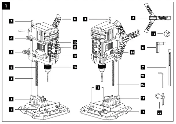
Device description (fig. 1-11
- Base plate
- Quick clamp
- Column
- Toothed rack for height adjustment
- Clamping lever for height adjustment
- Clamping lever for depth stop
- Depth stop
- Handle
- Pointer, depth stop
- Off switch
- On switch
- Speed control
- Spacer
- Chuck
- Wing screws for parallel stop
- Parallel stop
- Quick-clamp screw
- Laser ON/OFF switch
- Phillips screw (pointer)
- Scale
- Allen key, 4 mm
- Chuck key
- Marking
Scope of delivery
- 1 Drilling machine
- 1 Quick clamp (2)
- 1 Base plate (1)
- 1 Parallel stop (16)
- 1 Spacer (13)
- 1 handle (8)
- 1 Depth stop (7)
- 1 Clamping lever (6)
- 1 Allen key, 4 mm (21)
- 1 Chuck key (22)
- 1 Operating manual
- 1 Assembly material
Proper use
The bench drill is designed for drilling in metal, wood, plastic, and tiles.
Chuck clamping range: 1.5 – 13 mm.
The device is only intended to be used for DIY purposes. It was not designed for continuous commercial use. The device is not intended for use by people under the age of 16. Children under the age of 16 may only use the device when supervised.
The manufacturer is not liable for damage caused by improper use or incorrect operation.
Please observe that our equipment was not designed with the intention of use for commercial or industrial purposes. We as- some no guarantee if the equipment is used in commercial or industrial applications, or for equivalent work.
Safety instructions
General power tool safety warnings
![]() WARNING! Read all safety warnings, instructions, illustrations, and specifications provided with this power tool.
WARNING! Read all safety warnings, instructions, illustrations, and specifications provided with this power tool.
Failure to follow all instructions listed below may result in electric shock, fire, and/or serious injury.
Save all warnings and instructions for future reference. The term “power tool” in the warnings refers to your mains-operated (corded) power tool or battery-operated (cordless) power tool.
Work area safety
a) Keep the work area clean and well-lit.
Cluttered or dark areas invite accidents.
b) Do not operate power tools in explosive atmospheres, such as in the presence of flammable liquids, gases, or dust. Power tools create sparks that may ignite dust or fumes.
c) Keep children and bystanders away while operating a power tool. Distractions can cause you to lose control.
Electrical safety
a) Power tool plugs must match the outlet. Never modify the plug in any way. Do not use any adapter plugs with earthed (grounded) power tools. Unmodified plugs and matching outlets will reduce the risk of electric shock.
b) Avoid body contact with earthed or grounded surfaces, such as pipes, radiators, ranges, and refrigerators. There is an increased risk of electric shock if your body is earthed or grounded.
c) Do not expose power tools to rain or wet conditions. Water entering a power tool will increase the risk of electric shock.
b) Do not abuse the cord. Never use the cord for carrying, pulling, or unplugging the power tool. Keep cord away from heat, oil, sharp edges, or moving parts. Damaged or entangled cords increase the risk of electric shock.
e) When operating a power tool outdoors, use an extension cord suitable for outdoor use. Using a cord suitable for outdoor use reduces the risk of electric shock.
f) If operating a power tool in a damp location is unavoidable, use a residual current device (RCD) protected supply. The use of an RCD reduces the risk of electric shock.
Personal safety
a) Stay alert, watch what you are doing, and use common sense when operating a power tool. Do not use a power tool while you are tired or under the influence of drugs, alcohol, or medication. A moment of inattention while operating power tools may result in serious personal injury.
b) Use personal protective equipment. Always wear eye protection. Protective equipment such as a dust mask, non-skid safety shoes, hard hat, or hearing protection used for appropriate conditions will reduce personal injuries.
c) Prevent unintentional starting. Ensure the switch is in the off-position before connecting to a power source and/or battery pack, picking up or carrying the tool. Carrying power tools with your finger on the switch or energizing power tools that have the switch on invites accidents.
d) Remove any adjusting key or wrench before turning the power tool on. A wrench or a key left attached to a rotating part of the power tool may result in personal injury.
e) Do not overreach. Keep proper footing and balance at all times. This enables better control of the power tool in unexpected situations.
f) Dress properly. Do not wear loose clothing or jewelry. Keep your hair and clothing away from moving parts. Loose clothes, jewelry, or long hair can be caught in moving parts.
g) If devices are provided for the connection of dust extraction and collection facilities, ensure these are connected and properly used. The use of dust collection can reduce dust-related hazards.
h) Do not let familiarity gained from frequent use of tools allow you to become complacent and ignore tool safety principles. A careless action can cause severe injury within a fraction of a second.
Power tool uses and cares
a) Do not force the power tool. Use the correct power tool for your application. The correct power tool will do the job better and safer at the rate at which it was designed.
b) Do not use the power tool if the switch does not turn on and off. Any power tool that cannot be controlled with the switch is dangerous and must be repaired.
c) Disconnect the plug from the power source and/or remove the battery pack, if detachable, from the power tool before making any adjustments, changing accessories, or storing power tools. Such preventive safety measures reduce the risk of starting the power tool accidentally.
d) Store idle power tools out of the reach of children and do not allow persons unfamiliar with the power tool or these instructions to operate the power tool. Power tools are dangerous in the hands of untrained users.
e) Maintain power tools and accessories. Check for misalignment or binding of moving parts, breakage of parts, and any other condition that may affect the power tool’s operation. If damaged, have the power tool repaired before use. Many accidents are caused by poorly maintained power tools.
f) Keep cutting tools sharp and clean. Properly maintained cutting tools with sharp cutting edges are less likely to bind and are easier to control.
g) Use the power tool, accessories and tool bits, etc. in accordance with these instructions.
h) Keep handles and grasping surfaces dry, clean, and free from oil and greases, taking into account the working conditions and the work to be performed. Use of the power tool for operations different from those intended could result in a hazardous site. Slippery handles and grasping surfaces do not allow for safe handling and control of the tool in unexpected situations.
Service
a) Have your power tool serviced by a qualified repair person using only identical replacement parts. This will ensure that the safety of the power tool is maintained.
Drill safety warnings
a) The drill must be secured. An incorrectly secured drill can move or topple and this can result in injuries.
b) The workpiece must be clamped or fastened to the workpiece support. Do not drill into workpieces that are too small to be securely clamped. Holding the workpiece by hand can lead to injuries.
c) Do not wear gloves. Gloves can be caught by rotating parts or drilling debris and thus cause injuries.
d) Keep your hands away from the drilling area whilst the electrical tool is running. Contact with rotating parts or drilling debris can cause injuries.
e) The drill must be turning before it makes contact with the workpiece. Otherwise, the drill bit can catch in the workpiece and this can result in an unexpected movement of the workpiece and cause injuries.
f) If the drill becomes jammed, stop pressing downwards and switch the electrical tool off. Investigate and rectify the cause of the jamming. Jamming can result in an unexpected movement of the workpiece and can result in serious injuries.
g) Avoid long pieces of drill swarf by interrupting the downward pressure at regular intervals. Sharp metal swarf can become tangled and lead to injuries.
h) Never remove drilling debris from the drilling area whilst the electrical tool is running. To remove the swarf, move the drill away from the workpiece, switch off the electrical tool and wait until the drill has come to a standstill. Use an aid such as a brush or a hook to remove the swarf. Contact with rotating parts or drilling debris can cause injuries.
i) The permissible rotational speed for drill bits with a rated speed must be at least as high as the highest speed cited on the electrical tool. Accessories that rotate faster than permitted can break and fly off at high speed.
 Attention: Laser radiation Do not look into the beam Laser class 2
Protect yourself and your environment from accidents using suitable precautionary measures
Do not look directly into the laser beam with unprotected eyes.
- Never look into the path of the beam.
- Never point the laser beam towards reflecting surfaces and persons or animals. Even a laser beam with a low output can cause damage to the eyes.
- Caution – methods other than those specified here can result in dangerous radiation exposure.
- Never open the laser module. Unexpected exposure to the beam can occur.
- The laser may not be replaced with a different type of laser.
- Repairs of the laser may only be carried out by the laser manufacturer or an authorized representative.
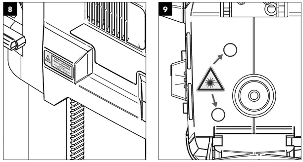
- Labeling and placement of warning stickers, see fig. 8 and9.
![]() WARNING! This electric tool generates an electromagnetic field during operation. This field can impair active or passive medical implants under certain conditions. In order to prevent the risk of serious or deadly injuries, we recommend that persons with medical implants consult with their physician and the manufacturer of the medical implant prior to operating the electric tool.
WARNING! This electric tool generates an electromagnetic field during operation. This field can impair active or passive medical implants under certain conditions. In order to prevent the risk of serious or deadly injuries, we recommend that persons with medical implants consult with their physician and the manufacturer of the medical implant prior to operating the electric tool.
Residual risks
Even when this electric tool is operated properly, residual risks still remain. The following hazards may arise in connection with the design and construction of this electric tool:
- Lung damage if a suitable dust protection mask is not worn.
- Hearing damage if suitable hearing protection is not worn.
- Damage to health resulting from hand/arm vibration if the device is used over an extended period of time or if it is not properly operated and maintained.
Technical data
AC motor…………………………………………….220 – 240 V~50 Hz
Nominal power S1 ……………………………………………… 710 Watt
Operating mode ………………………………………..S2 5min* 900W
Idle speed n0 …………………………………………….500 – 2600 min-1
Drill chuck clamping range ……………………………….1.5 – 13 mm.
Max. drill stroke………………………………………………………..70 mm
Size of base plate ………………………………………..320 x 305 mm
Distance chuck to bottom plate ………………………………. 280 mm
Weight approx. …………………………………………………………8,3 kg
Protection class …………………………………………………………. II /
Laser class ……………………………………………………………………….. 2
Laser wavelength ……………………………………………………. 650 nm
Laser power ……………………………………………………………< 1 mW
* After an uninterrupted operating period of 5 minutes, the device should be allowed to rest until its temperature has dropped to within 2 K (2° C) of room temperature.
The workpiece must have a minimum height of 3 mm and a minimum width of 45 mm. Make sure that the workpiece is always secured with the clamping device. Overhanging workpieces may have to be supported laterally by additional supports.
Noise
The noise levels have been determined in accordance with EN 62841.
Sound pressure level LpA …………………………………….. 89,6 dB(A)
Uncertainty KpA …………………………………………………………….3 dB
Sound power level LWA ……………………………………..102,6 dB(A)
Uncertainty KWA ……………………………………………………………3 dB
Wear hearing protection.
Excessive noise can result in a loss of hearing.
The above-mentioned noise emission values were measured in accordance with a standardised test procedure and can be used to compare one power tool with another. The pecified device emissions values can also be used for an initial estimation of the load.
Warning:
- The noise emission values can vary from the specified values during the actual use of the electric tool, depending on the type and the manner in which the electric tool is used, and in particular the type of workpiece being processed.
- Try to keep the stress as low as possible. For example, Limit working time. In doing so, all parts of the operating cycle must be taken into account (such as times in which the electric tool is switched off or times in which it is switched on, but is not running under a load).
Before commissioning
- Open the packaging and carefully remove the device.
- Remove the packaging material as well as the packaging and transport bracing (if available).
- Check whether the scope of delivery is complete.
- Check the device and accessory parts for transport damage.
- If possible, keep the packaging until the expiry of the warranty period.
ATTENTION
The device and the packaging are not children‘s toys! Do not let children play with plastic bags, films or small parts! There is a danger of choking or suffocating!
Before connecting the machine, make certain that the data on the type plate matches with the mains power data.
- Check the device for transport damage. Immediately report any damage to the transport company that delivered the electrical tool.
- Long supply cables (extension cable) should be avoided.
- Do not operate the electrical tool in damp or wet areas.
- Operate the electrical tool only in suitable areas (well ventilated).
Assembly
![]() Attention!
Attention!
Always make sure the device is fully assembled before com-missioning!
![]() Before connecting the machine to the mains power, make certain that the data on the type plate matches with the mains power data.
Before connecting the machine to the mains power, make certain that the data on the type plate matches with the mains power data.
![]() Warning! Always pull out the mains plug before carrying out adjustments on the device.
Warning! Always pull out the mains plug before carrying out adjustments on the device.
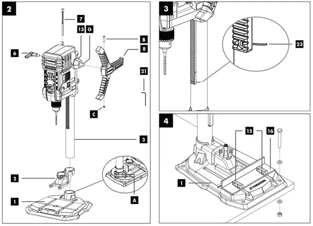
9.1 Assembling the base plate and column (fig. 2)
- Slide the quick clamp (2) over the column (3).
- Set the column (3) into the base plate (1) such that the guide pins on the bottom end of the column (3) engage with the groove in the mount on the base plate (1).
- Tighten the pre-assembled fastening screws (A) on the rear of the base plate (1) with the Allen key (21).
9.2 Fitting the parallel stop (fig. 4)
- Slide the parallel stop (16) into the grooves in the base plate (1).
- Ensure that the sliding blocks underneath the wing screws of the parallel stop (15) are properly engaged in the grooves of the base plate.
- Move the parallel stop (16) to the desired position and tighten the wing screws of the parallel stop (15) firmly.
9.3 Assembling the handle (fig. 2)
- Remove the pre-assembled fastening screw (B).
- Ensure that the spacer (13) is seated correctly.
- Slide the handle (8) onto the retainer (G) as shown in fig. 2.
- Place the nut (C) in the recess in the handle (8) and tighten the fixing screw (B).
9.4 Fitting the depth stop (fig. 2)
- Insert the depth stop (7) from above into the recess in the housing.
- Assemble the clamping lever for depth stop (6) as shown in fig. 2.
9.5 Fastening to a work surface (fig. 4)
Fasten the device to the work surface by bolting the base plate
(1) to the work surface.
Operation
10.1 Height adjustment (fig. 2, 3)
The position of the machine head can be adjusted to suit the workpiece height or the workpiece length.
- Hold the handle (8) firmly.
- Release the clamping lever for the height adjustment (5).
- Set the position of the machine head with the handle (8).
- Secure the position of the machine head with the height adjustment clamping lever (5).
Attention! In the lowest position of the machine head make sure that it does not move beyond the marking (23).
Use the clamping lever for height adjustment (5) to secure the machine head in this position. Otherwise, the guide could be damaged.
10.2 Setting the drilling depth (fig. 1, 11)
The drilling depth can be set with the depth stop (7).
- Release the clamping lever on the depth stop (6).
- Carry out a test drilling. Once the desired depth is reached, tighten the depth stop clamping lever (6) again.
- The depth stop (7) is now locked in the desired drilling depth.
- Then check the position of the depth stop. If the indicated dimension does not correspond to the actual drilling depth, the pointer (9) can be readjusted.
• Loosen the Phillips screw (19) on the pointer (9).
• Set the pointer (9) to the correct position to the scale (20).
• Re-tighten the Phillips screw (19).
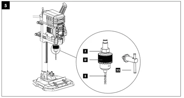
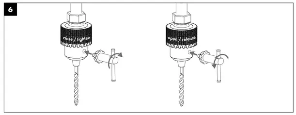
10.3 Clamping/releasing tools (fig. 5, 6) Caution! Do not leave the chuck key in the clamp hole. Doing so will cause the chuck key to be catapulted out, which could cause injury.
10.3.1 Clamping
- Insert the chuck key (22).
- Turn the chuck key (22) counterclockwise to open the clamping sleeve (D).
- Insert the insert tool (E).
- Hold the insert tool (E) in place.
- Turn the chuck key (22) clockwise to close the clamping sleeve (D) and to secure the insert tool.
- Check that the insert tool (E) is tight.
- Pull out the chuck key (22).
10.3.2 Releasing
- Insert the chuck key (22).
- Turn the chuck key (22) counterclockwise until the drill bit (E) can be removed.
- Pull out the chuck key (22).
10.4 Aligning workpieces (fig. 1)
- Switch on the laser cross using the On/off switch laser (18).
- The intersection of the two laser lines exactly indicates the centre point of the drill.
- Align your marking on the workpiece with the laser cross.
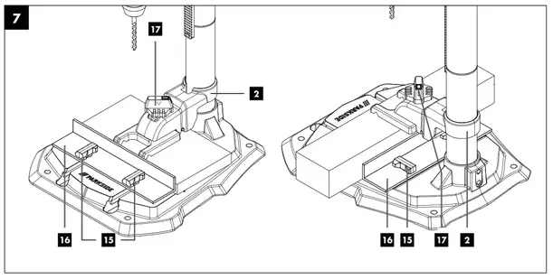
10.5 Clamping the workpiece (fig. 7)
It must be possible to clamp the workpiece securely. Do not work with workpieces that cannot be clamped securely.
The cut-out of the quick clamp must be centrally aligned with the hole to be drilled. Otherwise, the drill bit or the chuck could be obstructed by the quick clamp.
- Position the workpiece with the help of the laser cross.
- Loosen the quick clamp screw (17).
- Place the quick clamp (2) on the workpiece.
- Turn the quick clamp screw (17) clockwise to clamp the workpiece.
- Turn the quick clamp screw (17) anticlockwise to loosen the quick clamp (2).
10.6 Clamping larger workpieces (fig. 7)
Use the parallel stop (16) for larger workpieces:
- Loosen the wing screws for the parallel stop (15) and insert the parallel stop (16) into the grooves of the base plate.
- Tighten the wing screws for the parallel stop (15).
- Align your workpiece against the parallel stop (16) and clamp it with the quick clamp (2).
Warning! With workpieces that are wider or longer than the tabletop, ensure that these are adequately supported, e.g. through trestles or saw horses.
Workpieces that are longer or wider than the base plate of the tabletop drill can tip if they are not properly supported. If the workpiece tips, this can damage the chuck guard or the cutting tool.
10.7 Setting the drilling speed (fig. 1)
The correct speed must be set to suit the workpiece to be drilled and the tool diameter.
10.7.1 Electronic speed control
Use the electronic speed control to steplessly set the speed: Set the speed with the help of the speed control (12). The current speed can be seen using the mark on the speed control (12).
10.8 Switching on/off (fig. 1)
Switching on: Press the on switch (11) to switch the device on.
Switching off: Press the off switch (10) to switch the device off.
10.9 Drilling procedure (fig. 1, 7)
- Align the workpiece and clamp it.
- Start the device and set the speed.
- For drilling, move the handle (8) with uniform feed until the desired drilling depth is reached. When drilling into metal, interrupt the downward pressure briefly to break the swarf.
- After reaching the drilling depth, return the handle (8) to the starting position.
- Switch the device off.
Transport
![]() Warning! Unplug the mains plug prior to transpor• To transport the device hold it by the base plate (1).
Warning! Unplug the mains plug prior to transpor• To transport the device hold it by the base plate (1).
Cleaning and maintenance
![]() Warning! Pull out the mains plug before carrying out anadjustments, maintenance or repair work!
Warning! Pull out the mains plug before carrying out anadjustments, maintenance or repair work!
12. 1 General maintenance tasks
![]() Have tasks that are not described in this opering manual performed by a specialist workshop.Use only original parts. Let the device cool down
Have tasks that are not described in this opering manual performed by a specialist workshop.Use only original parts. Let the device cool down
before all maintenance and cleaning tasks.
![]() There is a risk of burn!
There is a risk of burn!
Before using the device each time, check the device for obvious defects such as worn or damaged parts, correct seating of screws or other parts. Replace damaged parts.
12.2 Cleaning
Do not use cleaning agents or solvents. Chemical substances could damage the plastic parts of the device. Never clean the device under running water.
- Clean the device thoroughly after each use.
- Clean the ventilation holes and the surface of the device with a soft brush or cloth.
- Remove swarf, dust and dirt with a vacuum cleaner if necessary.
- Lubricate the moving parts regularly.
12.3 Maintenance
The device has no parts that require maintenance.
12.4 Replacing the chuck (fig. 1, 5, 10)
![]() Warning! Pull out the mains plug!
Warning! Pull out the mains plug!
Tools required (not included in the scope of delivery):
1x open-ended wrench 27 mm
- Remove the insert tool as described in 10.3.2.
- Tighten the clamping sleeve (D) firmly by turning the chuck key (22) clockwise.
- Hold the chuck (14) with one hand while using the openended wrench (27 mm) to lower the nut (F) clockwise.
- Once the chuck (14) is loosened from the shaft seat, it can be removed.
- Fasten the new chuck in reverse order. When replacing the chuck, use only chucks approved by the manufacturer.
Order number: 390 6814 001
12.5 Service information
With this product, it is necessary to note that the following parts are subject to natural or usage-related wear, or that the following parts are required as consumables. Wear parts*: Carbon brushes, drill bit * may not be included in the scope of supply!
Storage
Store the device and its accessories in a dark, dry and frosfree place that is inaccessible to children. The optimum storage temperature lies between 5 and 30 °C. Store the electric ool in its original packaging. Cover the electric tool to protect it from dust or moisture. Store the operating manual with the electric tool.
Electrical connection
The electrical motor installed is connected and ready for operation. The connection complies with the applicable VDE and DIN provisions. The customer‘s mains connection s well as the extension cable used must also comply with these regula- tions.
14.1 Important information
In the event of overloading, the motor will switch itself off. After a cool-down period (time varies) the motor can be switched back on again.
14.2 Faulty power supply cables
The insulation on electrical connection cables is often damaged. This may have the following causes:
- Pressure points, where connection cables are passed through windows or doors.
- Kinks where the connection cable has been improperly fastened or routed.
- Places where the connection cables have been cut due to being driven over.
- Insulation damage due to being ripped out of the wall outlet.
- Cracks due to the insulation ageing.
Such damaged electrical connection cables must not be used and are life-threatening due to the insulation damage.
Check the electrical connection cables for damage regularly. Ensure that the connection cables are disconnected from electrical power when checking for damage.
Electrical connection cables must comply with the applicable VDE and DIN provisions. Only use connection cables with the marking H05VV-F. The printing of the type designation on the connection cable is mandatory.
If it is necessary to replace the connection cable, this must be done by the manufacturer or their representative to avoid safety hazards.
14.3 AC motor
The mains voltage must be 220 – 240 V~ 50Hz.
• Extension cables up to 25 m long must have a cross-section of 1.5 mm2
.Connections and repair work on the electrical equipment may only be carried out by electricians.
Please provide the following information in the event of any enquiries:
• Type of current for the motor
• Engine data – type plate
Disposal and recycling
The device is supplied in packaging to avoid transport damages. This packaging is raw material and can thus be used again or can be reintegrated into the raw material cycle. The device and its accessories are made of different materials, such as metals and plastics. Take defective components to special waste disposal sites. Check with your specialist dealer or municipal administration!
Do not throw old equipment away with household waste!
![]() This symbol indicates that this product must not be disposed of in household waste as per Waste Electrical and Electronic Equipment directive (2012/19/EU) and national laws. This product must be handed over at the intended collection point. This can be done, for example, by returning it when purchasing a similar product or delivering it to an authorised collection point for the recycling of old electrical and electronic devices. Improper handling of old devices can have negative effects on the environment and on human health due to potential hazardous materials which are often contained in old electrical and electronic devices. By disposing of this product properly, you are also contributing to the effective use of natural resources. Information about collection points for old devices can be found at your municipal authority, the local disposal provider, an authorised location for the disposal of old electrical and electronic devices or your waste collection service.
This symbol indicates that this product must not be disposed of in household waste as per Waste Electrical and Electronic Equipment directive (2012/19/EU) and national laws. This product must be handed over at the intended collection point. This can be done, for example, by returning it when purchasing a similar product or delivering it to an authorised collection point for the recycling of old electrical and electronic devices. Improper handling of old devices can have negative effects on the environment and on human health due to potential hazardous materials which are often contained in old electrical and electronic devices. By disposing of this product properly, you are also contributing to the effective use of natural resources. Information about collection points for old devices can be found at your municipal authority, the local disposal provider, an authorised location for the disposal of old electrical and electronic devices or your waste collection service.
Troubleshooting
| Fault | Possible cause | Remedy |
| Device does not start | Motor, cable or plug defective, building circuit breaker tripped | Check power outlet, mains connection cable, mains plug. Have repair carried out by electrical specialist. Check building circuit breakers. |
| On/off switch (11/10) defective | Repair by customer service department | |
| Motor defective | Repair by customer service department | |
| Heavy vibrations | Base plate (1) not fastened in place. | Secure machine to a work bench or similar |
| Drill bit not clamped centrally | Check drill bit in chuck (14) | |
| Motor overheats easily | Overloading of the motor, insufficient cooling of the motor. | Avoid overloading the motor while drilling,
remove dust from the motor in order to ensure optimal cooling of the motor. |
| Motor makes excessive noise | Coils damaged, motor defective. | Have checked by customer service department |
Warranty certificate
Dear Customer,
All of our products undergo strict quality checks to ensure that they reach you in perfect condition. In the unlikely event that your device develops a fault, please contact our service department at the address shown on this guarantee card. Of course, if you would prefer to call us then we are also happy to offer our assistance under the service number printed below. Please note the following terms under which guarantee claims can be made:
- These guarantee terms cover additional guarantee rights and do not affect your statutory warranty rights. We do not charge you for this guarantee.
- Our guarantee only covers problems caused by material or manufacturing defects, and it is restricted to the rectification of these defects or replacement of the device. Please note that our devices have not been designed for use in commercial, trade or industrial applications. Consequently, the guarantee is invalidated if the equipment is used in commercial, trade or industrial applications or for other equivalent activities. The following are also excluded from our guarantee: compensation for transport damage, damage caused by failure to comply with the installation/assembly instructions or damage caused by unprofessional installation, failure to comply with the operating instructions (e.g. connection to the wrong mains voltage or current type), misuse or inappropriate use (such as overloading of the device or use of non-approved tools or accessories), failure to comply with the maintenance and safety regulations, ingress of foreign bodies into the device (e.g. sand, stones or dust), effects of force or external influences (e.g. damage caused by the device being dropped) and normal wear resulting from proper operation of the device. The guarantee is rendered null and void if any attempt is made to tamper with the device.
- The guarantee is valid for a period of 3 years starting from the purchase date of the device. Guarantee claims should be submitted before the end of the guarantee period within two weeks of the defect being noticed. No guarantee claims will be accepted after the end of the guarantee period. The original guarantee period remains applicable to the device even if repairs are carried out or parts are replaced. In such cases, the work performed or parts fitted will not result in an extension of the guarantee period, and no new guarantee will become active for the work performed or parts fitted. This also applies when an on-site service is used.
- In order to assert your guarantee claim, please contact the service partner shown below. If the complaint is within the guarantee period, we will provide you with a return slip, with which you can return your defective device free of charge to us. It would help us if you could describe the nature of the problem in as much detail as possible. If the defect is covered by our guarantee then your device will either be repaired immediately and returned to you, or we will send you a new device. Of course, we are also happy offer a chargeable repair service for any defects which are not covered by the scope of this guarantee or for units which are no longer covered. To take advantage of this service, please send the device to our service address.
Service-Hotline (GB):
+800 4003 4003
(0,00 EUR/Min.)
Service-Email (GB):
[email protected]
Service Address (GB):
Forest Park & Garden
Coed Court, Taffsmead Road
Treforest, Ind. Estate, Pontypridd CF375SW
At www.lidl-service.com you can download this and many more manuals, product videos plus installation software.
The QR code takes you directly to the Lidl service page (www.lidl-service.com) and you can open your operating manual by entering the article number (IAN) 361816 _ 2010.


SCHEPPACH FABRIKATION VON HOLZBEARBEITUNGSMASCHINEN GMBH
Günzburger Str. 69
D-89335 Ichenhausen
Last Information Update


RECHARGEABLE BATTERY 20V 2 Ah + CHARGER PAP 20 B1 / PLG 20 C1
RECHARGEABLE BATTERY 20V 2 Ah + CHARGER
Translation of the original instructions
IAN 377764_2010


Before reading, unfold the page containing the illustrations and familiarise yourself with all functions of the device.
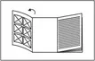
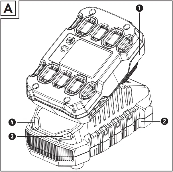
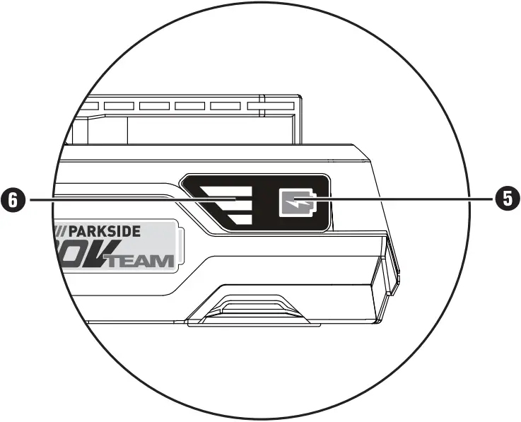
High-performance Li-Ion battery
Cell Balancing - longer battery life, increased battery lifespan.
Higher battery resources due to evenly used cells.
Maximises the charge potential.
| All Parkside tools and the chargers PLG 20 A1/PLG 20 C1/PLG 20 A4/PLG 20 A2/ PLG 20 A3/PLG 20 C3/PDSLG 20 A1 of the X20V Team series are compatible with the PAP 20 A1/PAP 20 A2/PAP 20 A3/PAP 20 B1/PAP 20 B3 battery pack. | |||
| Charging times
Charging currents |
2 Ah Battery pack PAP 20 A1/B1 |
3 Ah Battery pack PAP 20 A2 |
4 Ah Battery pack PAP 20 A3/B3 |
| max. 2,4 A PLG 20 A1/A4/C1 Charger |
60 min______ 2,4 A |
90 min______ 2,4 A |
120 min______ 2,4 A |
| max. 3,5 A PLG 20 A2 Charger |
45 min______ 3,5 A |
60 min______ 3,5 A |
80 min______ 3,5 A |
| max. 4,5 A PLG 20 A3/C3 Charger |
35 min______ 3,8 A |
45 min______ 4,5 A |
60 min______ 4,5 A |
| max. 4,5 A PDSLG 20 A1 Charger |
35 min______ 3,8 A |
45 min______ 4,5 A |
60 min______ 4,5 A |
Introduction
Congratulations on the purchase of your new appliance. You have chosen a high-quality product. The operating instructions are part of this product. They contain important information about safety, usage and disposal. Before using the product, please familiarise yourself with all operating and safety instructions. Use the product only as described and for the range of applications specified. Please also pass these operating instructions on to any future owner.
Intended use
This charger is exclusively intended for loading of PARKSIDE batteries of the PAP 20 A1/A2/A3/ B1/B3 series.
This rechargeable battery is suitable for:

The appliance is not intended for commercial use. Any other usage or modification of the appliance is deemed to be improper and carries a significant risk of accidents. The manufacturer accepts no responsibility for damage(s) attributable to misuse.
Features
- Battery pack
- High-speed charger
- Red charge control LED
- Green charge control LED
- Battery charge level button
- Battery display LED
Package contents
1 rechargeable battery 20V 2Ah
1 quick charger
1 operating manual
Technical data
Rechargeable Battery 20V 2Ah PAP 20 B1
Type LITHIUM ION
Rated voltage 20 V ⎓ (DC)
Capacity 2.0 Ah
Cells 5
Charger PLG 20 C1
INPUT
Rated voltage 230 - 240 V ~, 50 Hz (AC)
Rated power consumption 65 W
Fuse (internal) 3.15 A 
OUTPUT
Rated voltage 21.5 V ⎓ (DC)
Rated current 2.4 A
Charging time approx. 60 min
Protection class II /  (double insulation)

 WARNING!
■ Read all safety warnings and all instructions. Failure to follow the warnings and instructions may result in electric shock, fire and/or serious injury. Save all warnings and instructions for future reference.
Use and handling of the cordless electrical power tool
a) Charge a rechargeable battery unit using only the charger recommended by the manufacturer. Chargers are often designed for a particular type of rechargeable battery unit. There is the danger of fire if other types of rechargeable battery units are used.
b) Only the rechargeable battery units supplied are to be used with an electrical power tool. The use of other rechargeable battery units may lead to the danger of injury or fire.
c) When they are not being used, store rechargeable battery units away from paperclips, coins, keys, nails, screws or other small metal objects that could cause the contacts to be bridged. Short-circuiting the contacts of a rechargeable battery unit may result in heat damage or fire.
d) Fluids may leak out of rechargeable battery units if they are misused. If this happens, avoid contact with the fluid. If contact occurs, flush the affected area with water. Seek additional medical help if any of the fluid gets into your eyes. Escaping battery fluid may cause skin irritation or burns.
CAUTION! RISK OF EXPLOSION!
Never charge non-rechargeable batteries.


 Protect the rechargeable battery from heat; for example, from continuous exposure to sunlight, fire, water and moisture. There is a risk of explosion.
Extended safety guidelines
■ Do not use a damaged or modified battery. Damaged or modified batteries may behave unexpectedly and cause fires, explosions or pose a risk of injury.
■ Do not expose a battery to fire or excessively high temperatures. Fire or temperatures in excess of 130°C (265°F) can cause an explosion.
■ Follow all instructions regarding charging and never charge the battery or the cordless tool outside the temperature range given in the operating instructions.
Incorrect charging or charging outside of the permissible temperature range can destroy the battery and increase the risk of fire.
Safety guidelines for battery chargers
■ This appliance may be used by children aged 8 years and above and by persons with limited physical, sensory or mental capabilities or lack of experience and knowledge, provided that they are under supervision or have been told how to use the appliance safely and are aware of the potential risks. Do not allow children to use the appliance as a toy. Cleaning and user maintenance tasks may not be carried out by children unless they are supervised.
■ To avoid potential risks, damaged mains cables should be replaced by the manufacturer, their customer service department or a similarly qualified person.
 The charger is suitable for indoor use only.
WARNING!
■ To avoid potential risks, damaged mains cables should be replaced by the manufacturer, their customer service department or a similarly qualified person.
ATTENTION!
► This charger can only charge the following batteries: PAP 20 A1/PAP 20 A2/ PAP 20 A3/PAP 20 B1/PAP 20 B3.
► A current list of battery compatibility can be found at www.lidl.de/akku.
Before use
Charging the battery pack (see fig. A)
CAUTION!
► Always unplug the appliance before you remove the battery pack from or connect the battery pack to the charger.
NOTE
► Never charge the battery pack if the ambient temperature is below 10°C or above 40°C. If a lithium-ion battery is to be stored for an extended period, the charge level should be checked regularly. The optimum charge level is between 50% and 80%. The storage climate should be cool and dry and the ambient temperature should be between 0°C and 50°C.
♦ Connect the battery pack 1 to the high-speed battery charger 2 (see fig. A).
♦ Insert the power plug into the socket. The control LED 3 lights up red.
♦ The green control LED 4 indicates that the charging process is complete and the battery pack 1 is ready.
CAUTION!
♦ If the red control LED 3 flashes, this means that the battery pack 1 has overheated and cannot be charged.
♦ If the red and green control LEDs 3 4 both flash, this means that the battery pack 1 is broken.
♦ Push the battery pack 1 into the appliance.
♦ Switch off the charger for at least 15 minutes between successive charging sessions. Also disconnect the power plug from the mains power socket.
Checking the battery charge level
♦ Press the battery charge level button 5 to check the status of the battery (see also main diagram).
The status/remaining charge will be shown on the battery display LED 6 as follows:
RED/ORANGE/GREEN = maximum charge
RED/ORANGE = medium charge
RED = low charge - charge the battery
Maintenance and storage
■ If you do not intend to use the appliance for an extended period, remove the batteries and store it in a clean, dry place away from direct sunlight.
■ If a lithium-ion battery is to be stored for an extended period, the charge level should be checked regularly. The optimum charge level is between 50% and 80%. The optimum storage environment is cool and dry.
■ Never try to repair damaged batteries. Maintenance of batteries should only be carried out by the manufacturer or an approved customer service centre.
Kompernass Handels GmbH warranty
Dear Customer,
This appliance has a 3-year warranty valid from the date of purchase. If this product has any faults, you, the buyer, have certain statutory rights. Your statutory rights are not restricted in any way by the warranty described below.
Warranty conditions
The warranty period starts on the date of purchase. Please keep your receipt in a safe place. This will be required as proof of purchase.
If any material or manufacturing fault occurs within three years of the date of purchase of the product, we will either repair or replace the product for you or refund the purchase price (at our discretion). This warranty service requires that you present the defective appliance and the proof of purchase (receipt) within the three-year warranty period, along with a brief written description of the fault and of when it occurred.
If the defect is covered by the warranty, your product will either be repaired or replaced by us. The repair or replacement of a product does not signify the beginning of a new warranty period.
X 12 V and X 20 V Team Series battery packs come with a 3-year warranty valid from the date of purchase.
Warranty period and statutory claims for defects
The warranty period is not prolonged by repairs effected under the warranty. This also applies to replaced and repaired components. Any damage and defects present at the time of purchase must be reported immediately after unpacking. Repairs carried out after expiry of the warranty period shall be subject to a fee.
Scope of the warranty
This appliance has been manufactured in accordance with strict quality guidelines and inspected meticulously prior to delivery.
The warranty covers material faults or production faults. The warranty does not extend to product parts subject to normal wear and tear or to fragile parts which could be considered as consumable parts such as switches or parts made of glass.
The warranty does not apply if the product has been damaged, improperly used or improperly maintained. The directions in the operating instructions for the product regarding proper use of the product are to be strictly followed. Uses and actions that are discouraged in the operating instructions or which are warned against must be avoided.
This product is intended solely for private use and not for commercial purposes. The warranty shall be deemed void in cases of misuse or improper handling, use of force and modifications / repairs which have not been carried out by one of our authorised Service centres.
The warranty period does not apply to
■ Normal reduction of the battery capacity over time
■ Commercial use of the product
■ Damage to or alteration of the product by the customer
■ Non-compliance with safety and maintenance instructions, operating errors
■ Damage caused by natural hazards
Warranty claim procedure
To ensure quick processing of your case, please observe the following instructions:
■ Please have the till receipt and the item number (e.g. IAN 12345) available as proof of purchase.
■ You will find the item number on the type plate on the product, an engraving on the product, on the front page of the operating instructions (below left) or on the sticker on the rear or bottom of the product.
■ If functional or other defects occur, please contact the service department listed either by telephone or by e-mail.
■ You can return a defective product to us free of charge to the service address that will be provided to you. Ensure that you enclose the proof of purchase (till receipt) and information about what the defect is and when it occurred.

You can download these instructions along with many other manuals, product videos and installation software at www.lidl-service.com.
This QR code will take you directly to the Lidl service page (www.lidl-service.com) where you can open your operating instructions by entering the item number (IAN) 377764_2010.
WARNING!
► Have your appliances repaired by the Service Centre or a qualified electrician and only using genuine replacement parts. This will ensure that the safety of the appliance is maintained.
► Always ensure that the power plug and power cord are replaced only by the manufacturer of the appliance or the company customer service. This will ensure that the safety of the appliance is maintained.
Service
 Service Great Britain
Tel.: 0800 404 7657
E-Mail: [email protected]
 Service Ireland
Tel.: 1890 930 034
(0,08 EUR/Min., (peak))
(0,06 EUR/Min., (off peak))
E-Mail: [email protected]
IAN 377764_2010
Importer
Please note that the following address is not the service address. Please use the service address provided in the operating instructions.
KOMPERNASS HANDELS GMBH
BURGSTRASSE 21
44867 BOCHUM
GERMANY
www.kompernass.com
Disposal
 The packaging protects the appliance from damage during transport. The packaging materials have been selected for their environmental friendliness and disposal attributes, and are therefore recyclable.
Returning the packaging to the material cycle conserves raw materials and reduces the amount of waste that is generated. Dispose of packaging materials that are no longer needed in accordance with applicable local regulations.
 Do not dispose of power tools in your normal domestic waste!
European Directive 2012/19/EU requires that worn-out power tools be collected separately and recycled in an environmentally compatible manner.
 Do not dispose of batteries in your normal household waste!
Defective or worn-out rechargeable batteries must be recycled according to Directive 2006/66/EC.
Take the battery pack and/or tool to a nearby collection facility.
Please consult your local authorities regarding suitable disposal of worn-out power tools/battery packs.
 Dispose of the packaging in an environmentally friendly manner. Note the labelling on the packaging and separate the packaging material components for disposal if necessary. The packaging material is labelled with abbreviations (a) and numbers (b) with the following meanings:
1-7: plastics, 20-22: paper and cardboard, 80-98: composites.
 Your local community or municipal authorities can provide information on how to dispose of the worn-out product.
 The product is recyclable, subject to extended producer responsibility and is collected separately.
Notes on the EC Declaration of Conformity
This appliance complies with the basic requirements and other relevant provisions of the Electromagnetic Compatibility Directive 2014/30/EU and the Low-Voltage Directive 2014/35/EU.
The complete original Declaration of Conformity is available from the importer.

RoHS Directive
(2011/65/EU)*
* The manufacturer bears the full responsibility for compliance with this conformity declaration. The object of the declaration described above complies with the requirements of the Directive 2011/65/EU of the European Parliament and Council of 8 June 2011 on the limitations of use of certain dangerous substances in electrical and electronic appliances.
Ordering a replacement battery
If you want to order a replacement battery for your appliance, you can do so easily via the Internet on www.kompernass.com or by telephone.
Due to limited stocks, this item may sell out in a relatively short time.

NOTE
► Online ordering of replacement parts is not possible in all countries. In this case, please contact the Service hotline.
Telephone ordering
 Service Great Britain
Tel.: 0800 404 7657
 Service Ireland
Tel.: 1890 930 034
(0,08 EUR/Min., (peak))
(0,06 EUR/Min., (off peak))
To ensure a fast processing of your order, have the article number of your appliance to hand (e.g. IAN 377764) in case of questions. The article number can be found on the type plate or the title page of these instructions.
PAP 20 B1 + PLG 20 C1

KOMPERNASS HANDELS GMBH
BURGSTRASSE 21
44867 BOCHUM
GERMANY
www.kompernass.com
Last Information Update:
03 / 2021 Ident.-No.: PAP20B1+PLG20C1-122020-1
IAN 377764_2010 ![]()
Instruction Manual
2Ah 12V BATTERY 12-V-AKKU 2 Ah BATTERIE 12 V, 2 Ah PAPK 12 A3

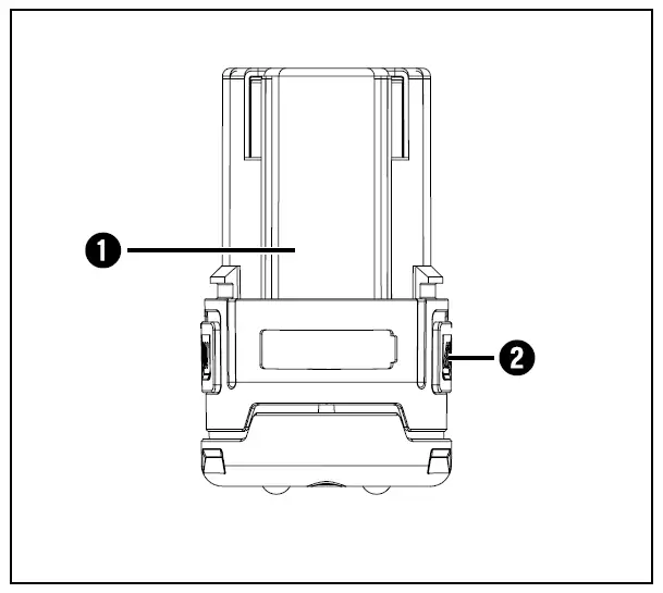
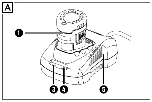
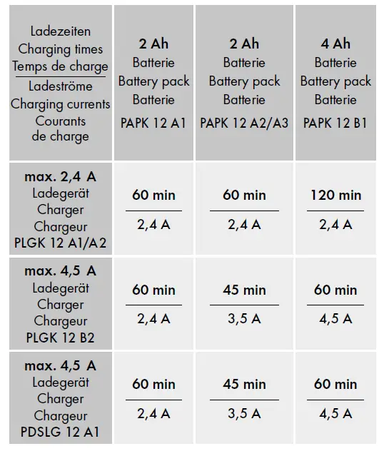
High-performance Li-Ion battery
Cell Balancing – longer battery life, increased battery lifespan. Higher battery resources due to evenly used cells. · Maximises the charge potential.
All Parkside tools and the chargers PLGK 12 A1/A2/B2/PDSLG 12 A1 of the X12V Team series are compatible with the PAPK 12 A1/A2/A3/B1 battery pack.
Introduction
Congratulations on the purchase of your new appli-ance. You have chosen a high-quality product. The operating instructions are part of this product. They contain important information about safety, usage and disposal. Before using the product, please familiarise yourself with all of the operating and safety instruc-tions. Use the product only as described and for the range of applications specified. Please also pass these operating instructions on to any future owner.
Intended use
This rechargeable battery is suitable for:
This rechargeable battery is not intended for commercial use. Any other usage of or modification to the appliance is deemed to be improper and carries a significant risk of accidents. The manufacturer accepts no responsibility for damage attributable to misuse.
Features
- Battery pack
- Release buttons
- Red charge control LED
- Green charge control LED
- High-speed charger (not supplied)
Package contents
- 1 2Ah 12V battery
- 1 set of operating instructions
Technical specifications
PAPK 12 A3
- Type: LITHIUM ION
- Rated voltage: 12 V (DC)
- Capacity: 2000 mAh/24 Wh
- Cells : 3
Use only X12V Team Series high-speed battery chargers to charge the battery pack:
High-speed battery charger: PLGK 12 A1 INPUT
INPUT
Rated current: 220–240 V ∼, 50–60 Hz (AC)
Rated power consumption: 50 W
OUTPUT
Rated voltage: 12 V (DC)
Rated current: 2400 mA
Charging time: approx. 60 min
Fuse (internal): 2 A T2A
Protection class II / (double insulation)
ATTENTION!
- This charger can only charge the following batteries: PAPK 12 A1/PAPK 12 A2/PAPK 12 A3/PAPK 12 B1.
- A current list of battery compatibility can be found at www.lidl.de/akku.
General Power Tool Safety Warnings
WARNING!
Read all safety warnings and all instructions. Failure to follow the warnings and instructions may result in electric shock, fire and/or serious injury. Save all warnings and instructions for future reference.
a) Charge a rechargeable battery unit using only the charger recommended by the manufacturer. Chargers are often designed for a particular type of rechargeable battery unit. There is the danger of fire if other types of rechargeable battery units are used.
b) Only the rechargeable battery units supplied are to be used with an electrical power tool. The use of other rechargeable battery units may lead to the danger of injury or fire.
c) When they are not being used, store rechargeable battery units away from paperclips, coins, keys, nails, screws or other small metal objects that could cause the contacts to be bridged. Short-circuiting the contacts of a rechargeable battery unit may result in heat damage or fire.
d) Fluids may leak out of rechargeable battery units if they are misused. If this happens, avoid contact with the fluid. If contact occurs, flush the affected area with water. Seek additional medical help if any of the fluid gets into your eyes. Escaping battery fluid may cause skin irritation or burns.
CAUTION! RISK OF EXPLOSION!
Never charge non-rechargeable batteries!

Protect the rechargeable battery from heat, for example from continuous exposure to sunlight, fire, water and moisture. There is a risk of explosion.
Extended safety guidelines
- Do not use a damaged or modified battery. Damaged or modified batteries may behave unexpectedly and cause fires, explosions or pose a risk of injury.
- Do not expose a battery to fire or excessively high temperatures. Fire or temperatures in excess of 130°C (265°F) can cause an explosion.
- Follow all instructions regarding charging and never charge the battery or the cordless tool outside the temperature range given in the operating instructions.
Incorrect charging or charging outside of the permissible temperature range can destroy the battery and increase the risk of fire.
Charging the battery pack (see fig. A)
CAUTION!
Always unplug the appliance before you remove the battery pack from or connect the battery pack to the charger.
NOTE
Never charge the battery pack if the ambient temperature is below 10°C or above 40°C. If a lithium-ion battery is to be stored for an extended period, the charge level should be checked regularly. The optimum charge level is between 50% and 80%. The storage climate should be cool and dry and the ambient temperature should be between 0°C and 50°C.
- Insert the battery pack 1 into the high-speed charger 5.
- Insert the power plug into the socket. The charge control LED 3 lights up red.
- The green charge control LED 4 indicates that charging is complete and the battery pack is ready for use.
- Push the battery pack 1 into the appliance.
- You should always switch the high-speed charger 5 off for at least 15 minutes between successive charging processes. Also disconnect the power plug from the mains power socket.
Maintenance and storage
- If you do not intend to use the battery for an extended period, remove it from the appliance and store it in a clean, dry place out of direct sunlight.
- If a lithium-ion battery is to be stored for an extended period, the charge level should be checked regularly. The optimum charge level is between 50% and 80%. The optimum storage environment is cool and dry.
- Never try to repair damaged batteries. Maintenance of batteries should only be carried out by the manufacturer or an approved customer service centre.
Kompernass Handels GmbH warranty
Dear Customer,
This appliance has a 3-year warranty valid from the date of purchase. If this product has any faults, you, the buyer, have certain statutory rights. Your statutory rights are not restricted in any way by the warranty described below.
Warranty conditions
The warranty period starts on the date of purchase. Please keep your receipt in a safe place. This will be required as proof of purchase.
If any material or manufacturing fault occurs within three years of the date of purchase of the product, we will either repair or replace the product for you or refund the purchase price (at our discretion). This warranty service requires that you present the defective appliance and the proof of purchase (receipt) within the three-year warranty period, along with a brief written description of the fault and of when it occurred.
If the defect is covered by the warranty, your product will either be repaired or replaced by us. The repair or replacement of a product does not signify the beginning of a new warranty period.
X 12 V and X 20 V Team Series battery packs come with a 3-year warranty valid from the date of purchase.
Warranty period and statutory claims for defects
The warranty period is not prolonged by repairs effected under the warranty. This also applies to replaced and repaired components. Any damage and defects present at the time of purchase must be reported immediately after unpacking. Repairs carried out after expiry of the warranty period shall be subject to a fee.
Scope of the warranty
This appliance has been manufactured in accord-ance with strict quality guidelines and inspected meticulously prior to delivery.
The warranty covers material faults or production faults. The warranty does not extend to product parts subject to normal wear and tear or to fragile parts which could be considered as consumable parts such as switches or parts made of glass.
The warranty does not apply if the product has been damaged, improperly used or improperly main-tained. The directions in the operating instructions for the product regarding proper use of the product are to be strictly followed. Uses and actions that are discouraged in the operating instructions or which are warned against must be avoided.
This product is intended solely for private use and not for commercial purposes. The warranty shall be deemed void in cases of misuse or improper handling, use of force and modifications / repairs which have not been carried out by one of our authorised Service centres.
The warranty period does not apply to:
- Normal reduction of the battery capacity over time
- Commercial use of the product
- Damage to or alteration of the product by the customer
- Non-compliance with safety and maintenance instructions, operating errors
- Damage caused by natural hazards
Warranty claim procedure
To ensure quick processing of your case, please observe the following instructions:
- Please have the till receipt and the item number (e.g. IAN 12345) available as proof of purchase.
- You will find the item number on the type plate on the product, an engraving on the product, on the front page of the operating instructions (below left) or on the sticker on the rear or bottom of the product.
- If functional or other defects occur, please contact the service department listed either by telephone or by e-mail.
You can return a defective product to us free of charge to the service address that will be provided to you. Ensure that you enclose the proof of purchase (till receipt) and information about what the defect is and when it occurred.
 You can download these instructions along with many other manuals, product videos and installation soft-ware at www.lidl-service.com.
This QR code will take you directly to the Lidl service page (www.lidl-service.com) where you can open your operating instructions by entering the item number (IAN) 351899_2007.
Service
Service Great Britain
Tel.: 0800 404 7657
E-Mail: [email protected]
Service Ireland
Tel.: 1890 930 034
(0,08 EUR/Min., (peak))
(0,06 EUR/Min., (off peak)) E-Mail: [email protected]
IAN 351899_2007
Importer
Please note that the following address is not the service address. Please use the service address provided in the operating instructions.
KOMPERNASS HANDELS GMBH BURGSTRASSE 21
44867 BOCHUM
GERMANY
www.kompernass.com
Disposal
 The packaging protects the device from damage during transport. The packaging materials have been selected for their environmental friendliness and disposal attributes, and are therefore recyclable.
Returning the packaging into the material cycle conserves raw materials and reduces the amount of waste generated. Dispose of packaging materials that are no longer needed in accordance with applicable local regulations.
 Do not dispose of batteries in your normal household waste!
Defective or worn-out rechargeable batteries must be recycled according to Directive 2006/66/EC. Take the battery pack and/or appliance to a nearby collection facility. Please consult your local authorities regarding suit-able disposal of worn out power tools/battery packs.
 Dispose of the packaging in an environ-mentally friendly manner.
Note the labelling on the packaging and separate the packaging material components for disposal if necessary. The packaging mate-rial is labelled with abbreviations (a) and numbers (b) with the following meanings: 1–7: Plastics, 20–22: Paper and cardboard, 80–98: Composites.
 Your local community or municipal authorities can provide information on how to dispose of the worn-out product.
 The product is recyclable, subject to extended producer
responsibility and is collected separately.
Notes on the EC Declaration of Conformity
This appliance complies with the essential requirements and other relevant provisions of the RoHS Directive 2011/65/EU*.
The complete original Declaration of Conformity is available from the importer.
* The manufacturer bears the full responsibility for compliance with this conformity declaration. The object of the declaration described above complies with the requirements of the Directive 2011/65/EU of the European
Parliament and Council of 8 June 2011 on the limitations of use of certain dangerous substances in electrical and electronic appliances.
Ordering a replacement battery
 If you want to order a replacement battery for your appliance, you can do so easily via the Internet on www.kompernass.com or by telephone.
Due to limited stocks, this item may sell out in a relatively short time.
NOTE
Online ordering of replacement parts might not be possible in some countries. If this is the case, please contact the Service hotline.
- The promotion is limited to one battery per customer/appliance and also to a period of two months after the promotion. Thereafter, the replacement battery can still be ordered as a replacement part under other conditions.
Telephone ordering
Service Great Britain Tel.: 0800 404 7657
Service Ireland Tel.: 1890 930 034
0,08 EUR/Min., peak · 0,06 EUR/Min., off peak
To ensure fast processing of your order, have the article number of your appliance to hand (e.g. IAN 351899) in case of questions. The article number can be found on the type plate or the title page of these instructions.
]]>Instruction Manual


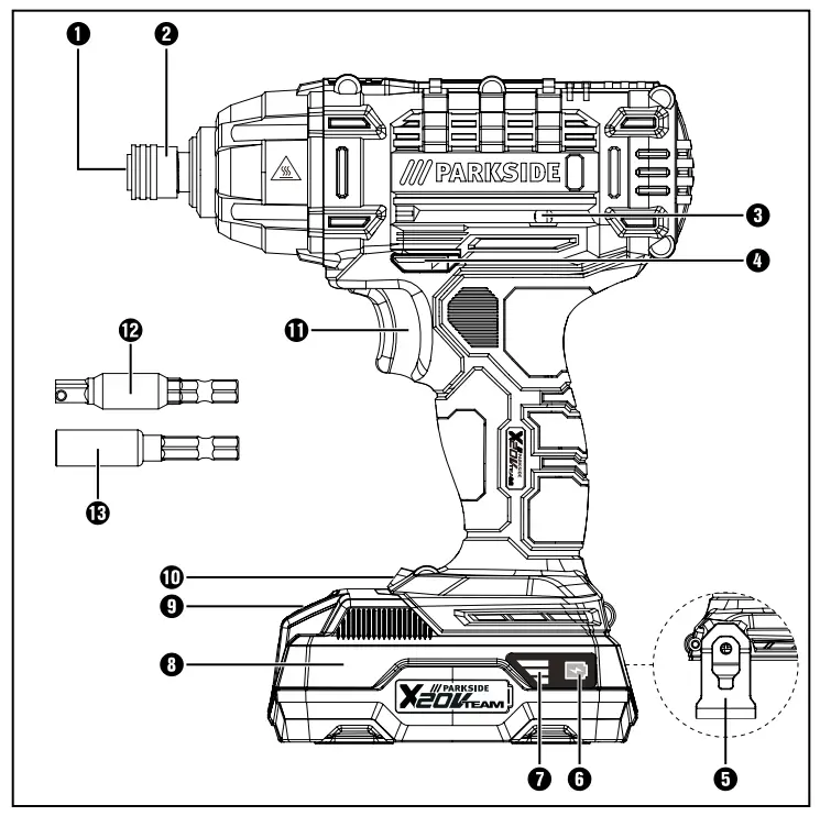
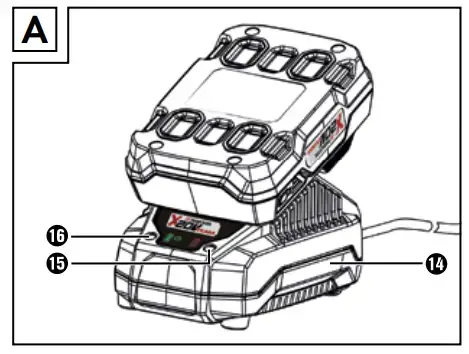
Todas las herramientas de Parkside y los cargadores PLG 20 A1/PLG 20 A4/PLG 20 B1/
PLG 20 A2/PLG 20 A3/PDSLG 20 A1 de la serie X20V Team son compatibles con el paquete
de baterías PAP 20 A1/PAP 20 A2/PAP 20 A3/PAP 20 B1/PAP 20 B3.
Tutti gli strumenti Parkside e i caricabatterie PLG 20 A1/PLG 20 A4/PLG 20 B1/PLG 20 A2/
PLG 20 A3/PDSLG 20 A1 della serie X20V Team sono compatibili con il pacco batteria
PAP 20 A1/PAP 20 A2/PAP 20 A3/PAP 20 B1/PAP 20 B3.
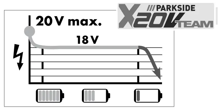
Introduction
Congratulations on the purchase of your new appliance. You have chosen a high-quality product . The operating instructions are part of this product . They contain important information about safety, usage, and disposal. Before using the product, please familiarise yourself with all operating and safety instructions. Use the product only as described and for the range of applications specified. Please also pass these operating instructions on to any future owner.
Intended use
This appliance is intended for screwing in and unscrewing screws as well as for tightening and loosening nuts. The appliance has clockwise/ anticlockwise rotation, a 1/4″ hexagon socket bit holder and an LED working light. The light on this appliance is intended to illuminate the immediate work area of the appliance. The rotary impact function of the appliance enables the power of the motor to be converted into uniform rotary impacts. The impact mechanism comes into effect during tightening and loosening.
The appliance is designed for use by adults. Young people under 16 years of age may only use the appliance under supervision. The manufacturer accepts no liability for damages caused by improper use or incorrect operation of the appliance.
Use this product only as described and for the areas of applications specified. The appliance is not intended for commercial use. Any other usage or modification of the appliance is deemed to be improper and carries a significant risk of accidents. The manufacturer accepts no responsibility for damage(s) attributable to misuse.
Features
- Tool holder
- Locking sleeve
- Bit holder (magnetic)
- Rotation direction switch/lock
- Belt clip
- Battery charge level button
- Battery display LED
- Battery pack*
- Release button for battery pack
- LED work light
- ON/OFF switch/Speed control
- Adapter to 1/4” square
- Bit holder
- High-speed charger*
- Red charge control LED
- Green charge control LED
Package contents
1 cordless impact driver PDSSA 20-Li A1
1 adapter from hex (1/4”) to square
1 1/4” extension (50 mm)
1 belt clip
1 carrying case
1 set of operating instructions
Technical data
Cordless impact driver PDSSA 20-Li A1
| Rated voltage | 20 V |
| Idle speed | n 0–2800 rpm |
| Rated stroke rate | 0–3600 ipm |
| Max . torque | 180 Nm |
| Suitable for metal screws | ≤ M8 |
| Suitable for wood screws | ≤ 8 mm Ø |
| Tool holder | 1/4” |
Battery: PAP 20 A1*
| Type | LITHIUM ION |
| Rated voltage | 20 V |
| Capacity | 2 Ah |
| Cells | 5 |
High-speed battery charger: PLG 20 A1*
INPUT
| Rated voltage | 230–240 V ∼, 50 Hz(AC) |
| Rated power consumption | 65 W |
| Fuse (internal) | 3 .15 A |
OUTPUT
| Rated voltage | 21 .5 V (DC) |
| Rated current | 2 .4 A |
| Charging time | approx . 60 min |
| Protection class | II / |
* BATTERY AND CHARGER NOT INCLUDED IN DELIVERY
Noise emission value
Noise measurement value determined in accordance with EN 62841 . The A-rated noise level of the tool is typically:
| Sound pressure level | LPA = 83 dB (A) |
| Uncertainty | KPA = 3 dB |
| Sound power level | LWA = 94 dB (A) |
| Uncertainty | KWA = 3 dB |
Vibration emission value
Total vibration values (vector total of three directions) determined in accordance with EN 62841:
Tightening screws and nuts of maximum
| permissible size | ah = 5 .677 m/s² |
| Uncertainty | K = 1 .5 m/s² |
Wear hearing protection!
NOTE
- The vibration emission values and the noise emission values given in these instructions have been measured in accordance with a standardised test procedure and can be used for comparison of the power tool with another tool .
- The specified total vibration values and the noise emission values can also be used to make a provisional load estimate .
 WARNING!
- Depending on the manner in which the power tool is being used, and in particular the kind of workpiece that is being worked, the vibration and noise emission values can deviate from the values given in these instructions during actual use of the power tool.
- Try to keep the load as low as possible . Measures to reduce the vibration load are, e .g . wearing gloves and limiting the working time . Wherein all states of operation must be included (e .g . times when the power tool is switched off and times where the power tool is switched on but running without load) .
![]() General power tool safety warnings
General power tool safety warnings
WARNING!
- Read all safety warnings, instructions, illus trations and specifications provided with this power tool. Failure to follow all instructions listed below may result in electric shock, fire and/or serious injury.
Save all warnings and instructions for future reference.
The term „power tool“ in the warnings refers to your mains-operated (corded) power tool or battery-operated (cordless) power tool .
Work area safety
a) Keep work area clean and well lit. Cluttered or dark areas invite accidents .
b) Do not operate power tools in explosive atmospheres, such as in the presence of flammable liquids, gases or dust. Power tools create sparks which may ignite the dust or fumes .
c) Keep children and bystanders away while operating a power tool. Distractions can cause you to lose control .
Electrical safety
a) Power tool plugs must match the outlet. Never modify the plug in any way. Do not use any adapter plugs with earthed (grounded) power tools. Unmodified plugs and matching outlets will reduce risk of electric shock .
b) Avoid body contact with earthed or grounded surfaces, such as pipes, radiators, ranges and refrigerators. There is an increased risk of electric shock if your body is earthed or grounded .
c) Do not expose power tools to rain or wet conditions. Water entering a power tool will increase the risk of electric shock .
d) Do not abuse the cord. Never use the cord for carrying, pulling or unplugging the power tool. Keep cord away from heat, oil, sharp edges or moving parts. Damaged or entangled cords increase the risk of electric shock.
e) When operating a power tool outdoors, use an extension cord suitable for outdoor use. Use of a cord suitable for outdoor use reduces the risk of electric shock .
f) If operating a power tool in a damp location is unavoidable, use a residual current device (RCD) protected supply. Use of an RCD reduces the risk of electric shock .
Personal safety
a) Stay alert, watch what you are doing and use common sense when operating a power tool. Do not use a power tool while you are tired or under the influence of drugs, alcohol or medication. A moment of inattention while operating power tools may result in serious personal injury .
b) Use personal protective equipment. Always wear eye protection. Protective equipment such as a dust mask, non-skid safety shoes, hard hat or hearing protection used for appropriate conditions will reduce personal injuries .
c) Prevent unintentional starting. Ensure the switch is in the offposition before connecting to power source and/or battery pack, picking up or carrying the tool. Carrying power tools with your finger on the switch or energising power tools that have the switch on invites accidents .
d) Remove any adjusting key or wrench before turning the power tool on. A wrench or a key left attached to a rotating part of the power tool may result in personal injury .
e) Do not overreach. Keep proper footing and balance at all times. This enables better control of the power tool in unexpected situations .
f) Dress properly. Do not wear loose clothing or jewellery. Keep your hair and clothing away from moving parts. Loose clothes, jewellery or long hair can be caught in moving parts .
g) If devices are provided for the connection of dust extraction and collection facilities, ensure these are connected and properly used. Use of dust collection can reduce dust- related hazards .
h) Do not let familiarity gained from frequent use of tools allow you to become complacent and ignore tool safety principles. A careless action can cause severe injury within a fraction of a second .
Power tool use and care
a) Do not force the power tool. Use the correct power tool for your application. The correct power tool will do the job better and safer at the rate for which it was designed .
b) Do not use the power tool if the switch does not turn it on and off. Any power tool that cannot be controlled with the switch is dangerous and must be repaired .
c) Disconnect the plug from the power source and/or remove the battery pack, if detach able, from the power tool before making any adjustments, changing accessories, or storing power tools. Such preventive safety measures 00reduce the risk of starting the power tool accidentally .
d) Store idle power tools out of the reach of children and do not allow persons unfamiliar with the power tool or these instructions to operate the power tool. Power tools are
dangerous in the hands of untrained users .
e) Maintain power tools and accessories. Check for misalignment or binding of moving parts, breakage of parts and any other condition that may affect the power tool’s operation.
If damaged, have the power tool repaired before use. Many accidents are caused by poorly maintained power tools .
f) Keep cutting tools sharp and clean. Properly maintained cutting tools with sharp cutting edges are less likely to bind and are easier to control .
g) Use the power tool, accessories and tool bits etc. in accordance with these instructions, taking into account the working conditions and the work to be performed. Use of the power tool for operations different from those intended could result in a hazardous situation .
h) Keep handles and grasping surfaces dry, clean and free from oil and grease. Slippery handles and grasping surfaces do not allow for safe handling and control of the tool in unexpected situations .
Battery tool use and care
a) Recharge only with the charger specified by the manufacturer. A charger that is suitable for one type of battery pack may create a risk of fire when used with another battery pack .
b) Use power tools only with specifically desig nated battery packs. Use of any other battery packs may create a risk of injury and fire .
c) When battery pack is not in use, keep it away from other metal objects, like paper clips, coins, keys, nails, screws or other small metal objects, that can make a connection from one terminal to another. Shorting the battery terminals together may cause burns or afire.
d) Under abusive conditions, liquid may be ejected from the battery; avoid contact. If contact accidentally occurs, flush with water.
If liquid contacts eyes, additionally seek medical help. Liquid ejected from the battery may cause irritation or burns .
e) Do not use a battery pack or tool that is damaged or modified. Damaged or modified batteries may exhibit unpredictable behaviour resulting in fire, explosion or risk of injury .
f) Do not expose a battery pack or tool to fire or excessive temperature. Exposure to fire or temperature above 130 °C (265°F) may cause explosion .
g) Follow all charging instructions and do not charge the battery pack or tool outside the temperature range specified in the instruc tions. Charging improperly or at temperatures outside the specified range may damage the battery and increase the risk of fire.
CAUTION! RISK OF EXPLOSION!
Never charge non-rechargeable batteries!
![]() Protect the rechargeable battery from heat, for example from continuous exposure to sunlight, fire, water and moisture. There is a risk of explosion .
Protect the rechargeable battery from heat, for example from continuous exposure to sunlight, fire, water and moisture. There is a risk of explosion .
Service
a) Have your power tool serviced by a qualified repair person using only identical replace ment parts. This will ensure that the safety of the power tool is maintained.
b) Never service damaged battery packs. Service of battery packs should only be performed by the manufacturer or authorized service providers.
Safety instructions specifically for impact screwdrivers
- Wear hearing protection when impact screwing. Exposure to loud noise can lead to hearing loss .
- Secure the workpiece! A workpiece securely held by a clamping device or vice is much safer than one held in your hand .
- Hold the power tool firmly. High torques can occur for brief periods while tightening and loosening screws .
- Wait until the power tool has come to a stand still before putting it down. The tool can jam, this leading to loss of control of the appliance .
- Always hold the tool by its insulated handles when working with power tools that may come into contact with hidden electrical cables.
Fasteners contacting a “live” wire may make exposed metal parts of the power tool “live” and could give the operator an electric shock .
Original accessories/additional equipment
Only use the accessories and additional equipment that are specified in the operating instructions and are compatible with the appliance.
WARNING!
- Do not use any accessories which are not recommended by PARKSIDE . This can lead to an electric shock and fire .
Safety guidelines for battery chargers
- This appliance may be used by children aged 8 years and above and by persons with limited phys-ical, sensory or mental capabilities or lack of experience and know-ledge, provided that they are under supervision or have been told how to use the appliance safely and are aware of the potential risks. Do not allow children to use the appliance as a toy. Cleaning and user mainte-nance tasks may not be carried out by children unless they are super-vised.
- To avoid potential risks, damaged mains cables should be replaced by the manufacturer, their customer service department or a similarly qualified person.
![]() The charger is suitable for indoor use only .
The charger is suitable for indoor use only .
WARNING!
- To avoid potential risks, damaged mains cables should be replaced by the manufacturer, their customer service department or a similarly qualified person.
ATTENTION!
- This charger can only charge the following batteries: PAP 20 A1/PAP 20 A2/ PAP 20 A3/PAP 20 B1/PAP 20 B3 .
- A current list of battery compatibility can be found at www .lidl .de/Akku .
![]() ATTENTION!
ATTENTION!
Hot surface . Risk of burns .
Before use
Charging the battery pack (see fig . A)
CAUTION!
- Always unplug the appliance before you remove the battery pack from or connect the battery pack to the charger .
NOTE
- Never charge the battery pack if the ambient temperature is below 10°C or above 40°C . If a lithium-ion battery is to be stored for an extended period, the charge level should be checked regularly . The optimum charge level is between 50% and 80% . The storage climate should be cool and dry and the ambient temperature should be between 0°C and 50°C .
- Connect the battery pack 8 to the rapid battery charger 14 (see Fig . A) .
- Insert the power plug into the socket . The control LED 15 lights up red .
- The green control LED indicates that the charging process is complete and the battery pack 8 is ready .
CAUTION!
- If the red control LED 15 flashes, this means that the battery pack 8 has overheated and cannot be charged.
- If the red and green control LEDs 15 16 both flash, this means that the battery pack 0 is defective.
- Insert the battery pack 8 back into the appliance.
- Switch off the charger for at least 15 minutes between successive charging sessions. Also disconnect the power plug from the mains power socket.
Attaching/disconnecting the battery pack to/from the appliance
Inserting the battery pack
♦ Push the rotation direction switch 4 into the middle position (lock) . Allow the battery pack 8 to click into the handle .
Removing the battery pack
- Press the release button 9 and remove the battery pack .
Checking the battery charge level
♦ Press the battery charge level button 6 to check the status of the battery (see also main diagram) .
The status/remaining charge will be shown on the battery display LED 7 as follows:
RED/ORANGE/GREEN = maximum charge
RED/ORANGE = medium charge
RED = low charge – charge the battery
Use
Switching on and off
Switching on
♦ To start the appliance, press the ON/OFF switch 11 and keep it pressed in . The LED work light 10 lights up when the ON/OFF switch 11 is depressed lightly or fully.
This allows for illumination of the work area in low lighting.
Switching off
♦ Release the ON/OFF switch 11 to switch off the appliance .
Setting the speed/tightening torque
- Press the ON/OFF switch 11 lightly for a low speed/tightening torque . Increasing the pressure increases the speed/tightening torque .
- The tightening torque depends on the selected speed and impact duration .
CAUTION!
- The tightening torque actually attained must always be checked with a torque wrench!
NOTE
- The integrated motor brake ensures rapid stoppage .
Changing the direction of rotation
- Change the direction of rotation by pressing the rotational direction switch 4 towards the left or right .
Inserting the bits
♦ Insert the adapter 12 or bit holder 12 into the tool holder 1.
♦ To do this, pull the locking sleeve 2 backwardsand allow the adapter 12 or bit holder 13 to engage .
Maintenance and cleaning
WARNING! RISK OF INJURY! Always switch the appliance off and remove the battery before carrying out any work on the appliance.
The appliance is maintenance-free .
- The appliance must always be kept clean, dry and free from oil or grease .
- Never allow liquids to get into the appliance .
- Use a soft, dry cloth to clean the housing .
Never use petrol, solvents or cleansers which can damage plastic . - If a lithium-ion battery is to be stored for an extended period, the charge level should be checked regularly . The optimum charge level is between 50% and 80% . The optimum storage environment is cool and dry .
NOTE
- Replacement parts not listed (such as carbon brushes, switch) can be ordered via our service hotline .
Kompernass Handels GmbH warranty
Dear Customer,
This appliance has a 3-year warranty valid from the date of purchase . If this product has any faults, you, the buyer, have certain statutory rights . Your statutory rights are not restricted in any way by the warranty described below .
Warranty conditions
The warranty period starts on the date of purchase .
Please keep your receipt in a safe place . This will be required as proof of purchase .
If any material or manufacturing fault occurs within three years of the date of purchase of the product, we will either repair or replace the product for you or refund the purchase price (at our discretion) .
This warranty service requires that you present the defective appliance and the proof of purchase (receipt) within the three-year warranty period, along with a brief written description of the fault and of when it occurred .
If the defect is covered by the warranty, your product will either be repaired or replaced by us .
The repair or replacement of a product does not signify the beginning of a new warranty period .
X 12 V and X 20 V Team Series battery packs come with a 3-year warranty valid from the date of purchase .
Warranty period and statutory claims for defects
The warranty period is not prolonged by repairs effected under the warranty . This also applies to replaced and repaired components . Any damage and defects present at the time of purchase must be reported immediately after unpacking . Repairs carried out after expiry of the warranty period shall be subject to a fee .
Scope of the warranty
This appliance has been manufactured in accordance with strict quality guidelines and inspected meticulously prior to delivery .
The warranty covers material faults or production faults. The warranty does not extend to product parts subject to normal wear and tear or to fragile parts which could be considered as consumable parts such as switches or parts made of glass. The warranty does not apply if the product has been damaged, improperly used or improperly maintained. The directions in the operating instruc-tions for the product regarding proper use of the product are to be strictly followed. Uses and actions that are discouraged in the operating instructions or which are warned against must be avoided.
This product is intended solely for private use and not for commercial purposes. The warranty shall be deemed void in cases of misuse or improper handling, use of force and modifications/repairs which have not been carried out by one of our authorised Service centres.
The warranty period does not apply to
- Normal reduction of the battery capacity over time
- Commercial use of the product
- Damage to or alteration of the product by the customer
- Non-compliance with safety and maintenance instructions, operating errors
- Damage caused by natural hazards
Warranty claim procedure
To ensure quick processing of your case, please observe the following instructions:
- Please have the till receipt and the item number (e .g . IAN 12345) available as proof of purchase .
- You will find the item number on the type plate on the product, an engraving on the product, on the front page of the operating instructions (below left) or on the sticker on the rear or bottom of the product.
- If functional or other defects occur, please contact the service department listed either by telephone or by e-mail.
- You can return a defective product to us free of charge to the service address that will be provided to you . Ensure that you enclose the proof of purchase (till receipt) and information about what the defect is and when it occurred.

You can download these instructions along with many other manuals, product videos and installation software at www.lidl-service.com .
This QR code will take you directly to the Lidl service page (www.lidl-service.com) where you can open your operating instructions by entering the item number (IAN) 360584_2010 .
WARNING!
- Have the power tool repaired by the service centre or a qualified electrician and only using genuine replacement parts. This will ensure that the safety of the appliance is maintained .
- Always ensure that the power plug or the mains cable is replaced only by the manu facturer of the appliance or by an approved customer service provider. This will ensure that the safety of the appliance is maintained .
Service
Service Great Britain
Tel .: 0800 404 7657
E-Mail: [email protected]
Service Malta
Tel .: 80062230
E-Mail: [email protected]
IAN 360584_2010
Importer
Please note that the following address is not the service address . Please use the service address provided in the operating instructions .
KOMPERNASS HANDELS GMBH
BURGSTRASSE 21
44867 BOCHUM
GERMANY
www.kompernass.com
Disposal
![]() The packaging is made from environmentally friendly material and can be disposed of at your local recycling plant .
The packaging is made from environmentally friendly material and can be disposed of at your local recycling plant .
![]() Do not dispose of power tools in your normal domestic waste!
Do not dispose of power tools in your normal domestic waste!
European Directive 2012/19/EU requires that worn-out power tools be collected separately and recycled in an environmentally compatible manner.
![]() Do not dispose of batteries in your normal household waste!
Do not dispose of batteries in your normal household waste!
Defective or worn-out rechargeable batteries must be recycled according to Directive 2006/66/EC . Take the battery pack and/or appliance to a nearby collection facility.
Please consult your local authorities regarding suitable disposal of worn out power tools/battery packs.
![]() Dispose of the packaging in an environmentally friendly manner. Note the labelling on the packaging and separate the packaging material components for disposal if necessary. The packaging material is labelled with abbreviations (a) and numbers (b) with the following meanings: 1–7: plastics, 20–22: paper and cardboard, 80–98: composites.
Dispose of the packaging in an environmentally friendly manner. Note the labelling on the packaging and separate the packaging material components for disposal if necessary. The packaging material is labelled with abbreviations (a) and numbers (b) with the following meanings: 1–7: plastics, 20–22: paper and cardboard, 80–98: composites.
![]() Your local community or municipal authorities can provide information on how to dispose of the worn-out product.
Your local community or municipal authorities can provide information on how to dispose of the worn-out product.
Translation of the original Conformity Declaration
We, KOMPERNASS HANDELS GMBH, docu ment officer: Mr . Semi Uguzlu, BURGSTR . 21, 44867 BOCHUM, GERMANY, hereby declare that this product complies with the following standards, normative documents and EC directives:
Machinery Directive
(2006/42/EC)
EC Low Voltage Directive (charger only)
(2014/35/EU)
EMC (Electromagnetic Compatibility)
(2014/30/EU)
RoHS Directive
(2011/65/EU)*
* The manufacturer bears the full responsibility for compliance with this conformity declaration . The object of the eclaration described above complies with the requirements of the Directive 2011/65/EU of the European Parliament and Council of 8 June 2011 on the limitations of use of certain dangerous substances in electrical and electronic appliances .
Applied harmonised standards
EN 62841-1:2015
EN 62841-2-2:2014
EN 60335-1:2012/A13:2017
EN 60335-2-29:2004/A2:2010
EN 62233:2008
EN 55014-1:2017
EN 55014-2:2015
EN 61000-3-2:2014
EN 61000-3-3:2013
EN 50581:2012
Type/appliance designation: Cordless impact driver PDSSA 20-Li A1
Year of manufacture: 01–2021
Serial number: IAN 360584_2010
Bochum, 09/12/2020

Semi Uguzlu
– Quality Manager –
We reserve the right to make technical changes in the context of further product development .
Ordering a replacement battery
If you want to order a replacement battery for your appliance, you can do so easily via the Internet on www .kompernass .com or by telephone.
Due to limited stocks, this item may sell out in a relatively short time.
NOTE
- Online ordering of replacement parts might not be possible in some countries . In this is the case, please contact the Service hotline .
Telephone ordering
Service Great Britain Tel .: 0800 404 7657
Service Malta Tel .: 80062230
To ensure a fast processing of your order, have the article number of your appliance to hand (e .g.
IAN 360584) in case of questions . The article number can be found on the type plate or the title page of these instructions.
KOMPERNASS HANDELS GMBH
BURGSTRASSE 21
44867 BOCHUM
GERMANY
www.kompernass.com
Last Information Update · Stand der Informationen:
12 / 2020 · Ident.-No.: PDSSA20-LiA1-122020-1
IAN 360584_2010
]]>
Introduction
Congratulations on the purchase of your new tool. You have chosen a high-quality product. The operating instructions are a part of this product. They contain important information about safety, usage and disposal. Before using the product, please familiarise yourself with all operating and safety instructions. Use the product only as described and for the range of applications specified. Please also pass these operating instructions on to any future owner.
Intended use
Long-handled hedge trimmer
This tool is intended for cutting and trimming hedges, bushes and flowering shrubs in the home garden. This is a hand-held tool with an integrated engine unit and linear reciprocating cutting blades.
WARNING
Hedge trimmers are not suitable for use by children.
Pole pruner
This tool is intended for trimming branches in trees
3-tooth cutting blade/strimmer
Use with 3-tooth cutting blade: for cutting high grass, undergrowth and light scrub.
Use with strimmer: for cutting grass and small weeds.
Extension attachment
ATTENTION
Do not use the extension attachment/boom53 in combination with the 3-tooth cutting blade/strimmer attachment!
Any other use that is not expressly permitted in these operating instructions may damage the tool and represents a serious risk for the user. Please observe the restrictions in the safety instructions. Comply with all national regulations that may restrict the use of the appliance. Any other usage of or modification to the tool is deemed to be improper and carries the risk of serious personal injury.
Not intended for commercial use.
PROHIBITED APPLICATIONS!
Due to the physical risk posed to the user, the tool may not be used to perform the following activities: cleaning footpaths and as a shredder for shredding tree and hedge sections. Furthermore, the tool may not be used to level ground elevations such as molehills. For safety reasons, the tool may not be used as a drive unit for any other devices. The user, not the manufacturer, is liable for any resulting damage or injuries of any kind.
Features
Engine unit PBK 4 A2-1
- Safety lock-out
- On/Off switch
- Carrying lug
- Round handle
- Rubber ring
- Clamping shell
- Locking screw
- Locking screw
- Boom
- Throttle control
- Spark plug connector
- Choke lever
- Starter pull cord
- Petrol tank
- Filler cap
- Fuel pump (primer)
- Air filter housing cover
Hedge trimmer attachment PBK 4 A2-3 - Handle
- Lock/release
- Gearbox casing
- Cutter bar
- Base plate (hedge trimmer)
- Control lever
- Front boom (hedge trimmer)
- Locking pin
- Drive shaft
Pole pruner attachment PBK 4 A2-4 - Front boom (pole pruner)
- Safety ring
- Oil filler cap
- Oil tank
- Blade
- Saw chain
- Bench grinder support
- Stop
- Locking pin
- Drive shaft
- Nut
- Thread
- Sprocket cover
- Blade guide
- Blade hole
- Guide rail
- Oil dispenser
- Chain sprocket
- Oil adjusting screw
- Chain tensioner pin
- Chain tensioning screw
Strimmer/cutter attachment PBK 4 A1-2 - 4 x screws (with washer)
- Protective guard
- 3-tooth cutting blade
- Strimmer with cutting filament
- Front boom (strimmer/3-tooth cutting blade)
- Locking pin
- Drive shaft
Extension attachment - Boom
- Locking screw
- Locking pin
- Drive shaft
Accessories - Carrying harness
- Protective cover for blade
- Chain guard
- Organic chain oil
- Oil/petrol mixing canister
- Safety goggles
- 4 mm hex key
- Spark plug wrench/flat-head screwdriver
- Tool bag
- Nut M19 x 1.0 (left-hand thread)
- Pressure plate cover
- Pressure plate
- Drive plate
- Cutting filament
- Funnel
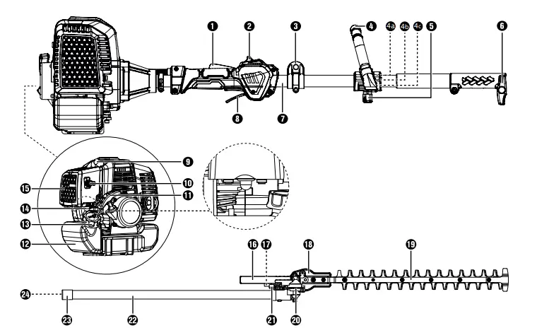
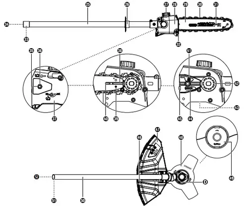
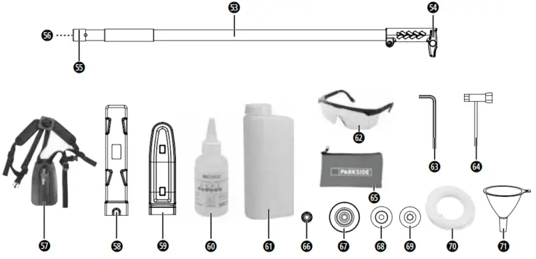
Package contents
- 1 engine unit
- 1 hedge trimmer attachment PBK 4 A2-3 (hereinafter hedge trimmer)
- 1 pole pruner attachment PBK 4 A2-4 (hereinafter pole pruner)
- 1 strimmer/cutter attachment PBK 4 A2-2
- 1 extension attachment
- 1 handle with barrier bar
- 1 strimmer with cutting filament
- 1 cutting filament (filament Ø: 2.4 mm/filament length: 6 m)
- 1 3-tooth cutting blade
- 1 carrying harness
- 1 chain guard
- 1 blade guard
- 1 oil/petrol mixing canister
- 1 100 ml organic chain oil
- 1 tool bag
- 1 4 mm hex key
- 1 spark plug wrench/flat-head screwdriver
- 1 safety goggles PBKZ 1 A1
- 1 funnel
- 1 set of operating instructions
Technical specifications
Engine unit PBK 4 A2-1
- Engine type 2-stroke engine, air-cooled,
- chrome cylinder
- Engine output (max.) 1.45 kW/1.97 hp
- Cylinder capacity 51.7 cm³
- Engine idle speed 3000 rpm
- Max. engine speed
- with 3-tooth cutting blade 9200 rpm
- with strimmer 8700 rpm
- with chainsaw 9200 rpm
- with hedge trimmer 9200 rpm
- Max. cutting speed
- with 3-tooth cutting blade 6900 rpm
- with strimmer 6525 rpm
- with chainsaw 20 m/s
- with hedge trimmer 1490 strokes/min
- Ignition electronic
- Drive centrifugal clutch
- Weight (empty tank) approx. 5.6 kg
- Tank capacity 1200 cm3
- Spark plug CDK L8RTC
- Fuel consumption at maximum engine output 0.78 kg/h
- Specific fuel consumption at maximum engine output 560 g/kWh
Hedge trimmer PBK 4 A2-3
- Cut length 480 mm
- Tooth spacing 27 mm
- Weight (ready for use) approx. 2.24 kg
Pole pruner PBK 4 A2-4
- Weight (ready for use) approx. 1.6 kg Oil tank, recommended fill level 140 ml3
- Cut length approx. 300 mm
- Blade Oregon type 120SDEA041
- Saw chain Oregon 91P045X
Strimmer/cutting blade attachment PBK 4 A2-2
Strimmer with cutting filament (IAN 352083)
- Filament cutting circle Ø 430 mm
- Filament length 6.0 m
- Filament Ø 2.4 mm
3-tooth cutting blade (IAN 352083)
- Cutting blade cutting diameter Ø 255 mm
Noise and vibration information:
Noise measurement determined in accordance with ISO 22868, EN ISO 10517. The A-rated noise level is typically as follows:
Hedge trimmer
| Sound pressure level | LpA = | 98.8 | dB(A) |
| Uncertainty | KWA= | 3 | dB(A) |
| Sound power level | LWA = | 109.7 | dB(A) |
| Guaranteed sound power level | LWA = | 114.00 | dB(A) |
| Pole pruner | |||
| Sound pressure level | LpA = | 99.0 | dB(A) |
| Uncertainty | KWA= | 1.98 | dB(A) |
| Sound power level | LWA = | 108.8 | dB(A) |
| Uncertainty | KWA= | 3 | dB(A) |
| 3-tooth cutting blade | |||
| Sound pressure level | LpA = | 98.9 | dB(A) |
| Uncertainty | KpA = | 3 | dB(A) |
| Sound power level | LWA = | 109.6 | dB(A) |
| Uncertainty | KWA= | 1.98 | dB(A) |
| Strimmer | |||
| Sound pressure level | LpA = | 99.5 | dB(A) |
| Uncertainty | KpA = | 3 | dB(A) |
| Sound power level | LWA = | 110.10 | dB(A) |
| Uncertainty | KWA= | 1.98 | dB(A) |
 Wear ear muffs to prevent hearing damage!
Vibration values (vector total of three directions) determined in accordance with EN 11806-1, EN ISO 10517, EN ISO 11680-1
Hedge trimmer
| Vibration on the front handle | vibration emission value ah,D = 6.15 m/s2 Uncertainty K = 1.5 m/s |
| Vibration on the rear handle | vibration emission value ah,D = 8.37 m/s2 Uncertainty K = 1.5 m/s2 |
| Pole pruner Vibration on the front handle | vibration emission value ah,D = 7.96 m/s2 Uncertainty K = 1.5 m/s2 |
| Vibration on the rear handle | ibration emission value ah,D = 7.41 m/s2 Uncertainty K = 1.5 m/s2 |
| Strimmer Vibration on the front handle | Vibration emission value ah,D = 7.99 m/s2 Uncertainty K = 1.5 m/s |
| Vibration on the rear handl | vibration emission value ah,D = 7.39 m/s2 Uncertainty K = 1.5 m/s |
| 3-tooth cutting blade Vibration on the front handle | vibration emission value ah,D = 6.2 m/s2 Uncertainty K = 1.5 m/s2 |
| Vibration on the rear handle | vibration emission value ah,D = 8.49 m/s2 Uncertainty K = 1.5 m/s2 |
NOTE
The vibration level specified in these instructions has been measured in accordance with the standardised measuring procedure specified in EN 11806-1,EN ISO 10517, EN ISO 11680-1 and can be used to make equipment comparisons. The specified vibration emission value can also be used to make an initial exposure estimate.
WARNING
The vibration level varies in accordance with use and may be higher than the value specified in these instructions in some cases. There is a risk of underestimation of the vibration load if the tool is used regularly in this manner. To estimate the vibration load during a specific working period accurately, periods during which the tool is switched off (or running, but not being used) must also be taken into account. This can significantly reduce the vibration load over the total working period.
WARNING
You can reduce the vibration risk, for example, the risk of Raynaud’s phenomenon, by taking regular breaks during which you rub your hands together.
Explanation of the symbols used


Safety instructions
MPORTANT! READ CAREFULLY BEFORE USE! KEEP FOR YOUR RECORDS.
Operational safety instructions for hedge trimmers
NOTE
- The hedge trimmer is supplied completely assembled.
- Instructions and illustrations regarding the settings and use of the hedge trimmer and/or its controls, maintenance and lubrication by the user can be found in these instructions and on the fold-out page.
- Notes on the working position (see fold-out page).
- Notes on the operating controls (see fold-out page).
- Note on the safe handling of fuel (see section “Preparation”, point f).
- These instructions contain information on the recommended replacement or repair of parts, the customer service and specification of spare parts to be used, inasmuch as they affect the health and safety of the user.
- The explanation of all graphical symbols, information, features and
technical specifications on the hedge trimmer as well as the procedure in the event of accidents and malfunctions can be found in these instructions. - Blocked tool: remove the jammed material from the cutter bar 18.
WARNING
- Do not allow children to use the hedge trimmer under any circumstances.
- Stay alert, watch what you are doing and use common sense when operating the tool. Do not use the tool while you are ill, tired or under the influence of drugs, alcohol or medication. A moment of inattention while operating the tool may result in serious personal injury.
- Avoid improper use. Use the appliance only as described in the section “Intended use”.
 Familiarise yourself with the operating instructions before you operate the tool.
Preparation
a) THE HEDGE TRIMMER CAN CAUSE SERIOUS INJURIES! Read the instructions on correct handling, preparation, maintenance, starting and stopping the hedge trimmer very carefully. Familiarise yourself with all manual controls and the proper use of the hedge trimmer.
b) Do not allow children to use the hedge trimmer under any circumstances. Children, adolescents and people with reduced physical, sensory or mental capabilities must not use the hedge trimmer. The only exception to this are young people over the age of 16 who are being trained by a specialist.
c) Beware of overhead power lines.
d) Do not use the hedge trimmer while anyone, especially children, is in the vicinity.
e) Wear appropriate clothing! Do not wear loose clothing or jewellery that could get caught in moving parts. We recommend wearing heavy-duty gloves, non-slip footwear and goggles.
f) Handle fuel carefully. It is highly flammable and the vapours are explosive.
The following points should be followed:
– Use only specially-designed containers.
– Never open the tank filler cap or top up the petrol tank while the engine is running or hot. Allow the engine and the exhaust components to cool down before refuelling.
– Do not smoke.
– Refuel outside only.
– Never store the hedge trimmer or the fuel tank in a room where there is an open flame, for example, in a hot water boiler.
– If the petrol has overflowed, do not attempt to start the engine. Remove the appliance from the fuel-contaminated area before restarting.
– Always replace the filler cap after refuelling and close it securely.
– Draining the tank should only be done in the open.
g) If the cutting unit comes in contact with a foreign object or if the operating noise increases or the hedge trimmer starts to vibrate abnormally, stop the engine and allow the hedge trimmer to come to a standstill. Pull the spark plug connector off the spark plug and take the following action:
– check for damage;
– check for loose parts and secure all the loose parts;
– replace damaged parts with equivalent parts or have them repaired.
 Wear ear muffs!
 Wear safety goggles!
Familiarise yourself with the operation of the hedge trimmer so that you know how to stop the tool immediately in an emergency
Operation
a) Switch off the engine before:
– cleaning or removing blockage;
– inspection, maintenance or work on the hedge trimmer;
– setting the working position of the cutting unit;
– if the hedge trimmer is to be left unattended.
b) Always make sure that the hedge trimmer is in the proper working position before the engine is started.
c) During operation of the hedge trimmer, always ensure that you have firm footing.
d) Do not use the hedge trimmer if it has a defective or badly worn cutting unit.
e) To minimise the risk of fire, ensure that the engine and the silencer are free of residues, leaves or leaked lubricant.
f) Ensure that all supplied handles and safety guards are mounted when operating the hedge trimmer. Never attempt to operate an incompletely assembled hedge trimmer or a hedge trimmer with non-approved modifications.
g) Always use both hands if the hedge trimmer is equipped with two handles.
h) Always familiarise yourself with your environment and be aware of potential dangers that you may not be able to hear because of the noise of the hedge trimmer.
Maintenance and storage
a) When you stop working with the hedge trimmer in order to carry out maintenance, inspection or storage, switch off the engine, pull the spark plug connector from the spark plug and ensure that all rotating parts have come to a standstill. Allow the appliance to cool down before carrying out an inspection, adjustments, etc.
b) Store the hedge trimmer where the petrol vapours cannot come into contact with flames or sparks. Always allow the hedge trimmer to cool down before storage.
c) When transporting or storing the hedge trimmer, cover the cutting unit with the protective cover for the cutting unit.
Supplementary safety instructions for hedge trimmers
Environmental safety
- Only operate the hedge trimmer in daylight or good artificial light.
- While trimming, make sure that you do not come into contact with objects such as wire fences or plant supports. They could cause damage to the cutter bar 18. Inspect the hedge to be cut carefully and remove any wires or other foreign bodies.
- Be aware of your environment and all possible hazards that you may be unable to hear while cutting the hedge.
DANGER
In the event of imminent danger or an emergency, switch off the engine immediately.
Electrical safety
Hold the power tool only by the insulated grips as the cutting blades could come into contact with hidden power lines. Contact between the blades and a live wire may make exposed metal parts of the power tool live and could give the operator an electric shock.
Personal safety
- During operation, no other person or animal may be within a radius of 15 metres. The operator is responsible for third parties within the working area.
- During operation, ensure that you have proper footing and balance at all times.
- Never touch the cutter bar 18 of the hedge trimmer.
- Keep your hands away from the cutting blades. Do not attempt to clear cuttings or hold onto the material you are cutting while the blades are still in motion. Remove any jammed clippings only when the tool has been switched off. A moment of inattention while operating the hedge trimmer may result in serious personal injury.
- Wait until the tool has come to a standstill before putting it down.
Use and handling
ATTENTION!
Between tasks or after completion of a task, do not set the cutter bar 19 down on its tip as this could cause damage to the cutter bar 19.
- Before use, always check that the blades, the blade screws and other parts of the cutting tool are not worn or damaged. Never work with a damaged or heavily worn blade.
- After making adjustments to the working angle, check whether both setting levers are clicked firmly into place. If one of the setting levers remains open, the second could be unintentionally released by a branch,and the cutter bar 19 could swing down.
- Never use the hedge trimmer with defective or missing safety guards.
- Never grasp the hedge trimmer by the safety guards.
- Carry the hedge trimmer by the front handle when switched off, with the cutter bar facing away from your body. When transporting or storing the hedge trimmer, always put on the protective cover. Careful handling of the tool reduces the likelihood of accidental contact with the moving blades.
- Store the hedge trimmer in a dry, high or locked location, out of the reach of children.
- Do not attempt to repair the equipment unless you have received the necessary training.
- For safety’s sake, change worn or damaged parts.
DANGER
In the event of imminent danger or an emergency, switch off the engine immediately.
Operational safety instructions for pole pruners
CAUTION! RISK OF INJURY!
To prevent injuries, never touch the tool above the safety ring 26 while it is running.
Preparation
- Always wear a hard hat, ear muffs and safety gloves. Also wear safety goggles to prevent splashes of oil or sawdust from getting into your eyes. Wear a dust mask to protect yourself from dust.
- Wear sturdy, non-slip boots.
- Do not use the tool in the rain.
- Before use, check the tool’s safety condition, especially the blade and the saw chain.
- Do not use the tool near power lines. Maintain a minimum distance of 10 m to above-ground power lines.
Electrical safety
- Do not use the tool in a potentially explosive environment containing flammable liquids, gases or dusts. The sparks generated by the appliance could ignite the vapours or gases.
- Tools with defective switches must be repaired immediately to avoid damage or injuries.
Personal safety
- Never use the tool while standing on a ladder.
- Do not lean too far forward while using the tool. Ensure that you are standing firmly, and keep your balance at all times. Use the supplied carrying harness to distribute the weight evenly on your body.
- To avoid injuries due to falling branches, do not stand under the branches that you want to cut off. Be aware of branches that may spring back and cause injuries. Work at an angle of approximately 60°.
- Be aware that the tool can kick back.
- Keep an eye on the branches being cut as well as on falling material to avoid tripping.
- Cover the guide rail and the chain with the cover during transport and storage.
- Avoid unintentional starting of the tool.
- Store the tool out of the reach of children. Only those who are fully acquainted with the operating instructions and the tool may operate the tool.
Use and handling
- Never start the tool before the blade, saw chain and sprocket covers have been fitted correctly.
- Do not cut any wood that is lying on the ground and do not attempt to saw roots that are protruding from the soil. Avoid dipping the saw chain into the soil at all costs, as this could blunt the saw chain.
- If the tool accidentally comes into contact with a solid object, switch off the engine immediately and inspect the tool for damage.
- After 30 minutes of work, take a break of at least one hour. Change your working position frequently.
- If the pole pruner is shut down for maintenance, inspection or storage, switch off the engine, pull the spark plug connector from the spark plug and ensure that all rotating parts have come to a standstill. Allow the appliance to cool down before carrying out an inspection, adjustments, etc.
- Service the tool carefully. Check for misalignment or binding of moving parts, breakage of parts and any other damage that may impair the tool’s operation. If damaged, have the power tool repaired before use.Many accidents are caused by poorly maintained tools.
- Keep cutting tools sharp and clean. Properly maintained cutting tools with sharp cutting edges are less likely to bind and are easier to control.
- Have the tool checked by qualified specialists. Use only replacement parts recommended by the manufacturer.
Precautionary measures against kickback
CAUTION! KICKBACK
Be aware of the danger of kickback when working with the tool. There is a risk of personal injury. You can avoid kickbacks by being careful and using the correct sawing technique.
- Contact with the tip of the rail can in some cases lead to an unexpected backward reaction resulting in the guide rail flying upwards towards the operator (see Fig. A)
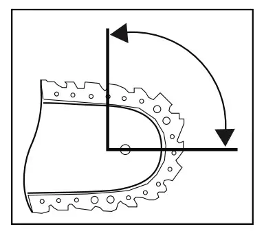
- Kickbacks can occur if the tip of the guide rail touches an object or if the wood bends and the saw chain gets caught in the cut (see Fig. B).
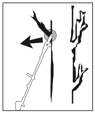
- If the saw chain jams in the upper edge of the guide rail, the rail can kick back violently towards the operator.
- Any such reaction can lead to you losing control over the saw and possibly injuring yourself. Do not rely solely on the chainsaw’s built-in safety devices. As the user of a chainsaw, you can take a number of measures to avoid accidents and injury. A kickback is caused by incorrect use or misuse. It can be avoided by taking proper precautions as given below:
- Hold the saw firmly with both hands, with your thumb and fingers around the handles of the chainsaw. Position your body and arms so you can withstand kickback forces. If suitable measures are taken, the operator can control the kickback forces. Never let go of the chainsaw.
- Avoid any abnormal posture and do not saw above shoulder height. This will prevent inadvertent contact with the tip of the rail and allows better control of the chainsaw in unexpected situations.
- Always use replacement rails and saw chains specified by the manufacturer. Incorrect replacement rails and saw chains can lead to tearing of the saw chain and/or kickback.
- Follow the manufacturer’s instructions for sharpening and maintenance of the saw chain. Setting the depth limiter too low can increase the risk of kickback.
- Do not saw with the tip of the blade. It can cause kickbacks.
- Ensure that there are no objects on the ground that you can trip over.
Operational safety instructions for strimmers
Preparation
- Wear close-fitting clothes that offer good protection, such as long trousers, sturdy work shoes, heavy-duty protective gloves, a hard hat, a protective mask for your face or safety goggles to protect your eyes and good ear plugs or other hearing protection against noise.
- Always use the supplied carrying harness.
- Always ensure that the handles are dry and clean and that no petrol mixture is present.
- Prior to starting work, check the area for objects such as pieces of metal, bottles, stones, etc, that could get thrown up and cause injuries to the user.
- Before starting the engine, make sure that the strimmer is not in contact with any obstacles.
- Do not use the tool until you have familiarised yourself with its use.
Electrical safety
- Never use the tool near highly flammable liquids or gases, either inclosed rooms or in the open. This may result in explosions and/or fire.
- Do not work with a damaged or incomplete tool or a tool that has been modified without the consent of the manufacturer. Never use the tool with defective protective equipment. Do not use the tool if it has a defective On/Off switch. If the tool has been dropped, check for significant damage or defects.
Personal safety
- This tool may only be operated, adjusted and maintained by appropriately trained individuals and adults.
- If you are not familiar with the tool, practice handling the tool while the engine is off.
- Do not touch the exhaust.
- Do not operate the tool under the influence of alcohol or drugs.
- Always hold the tool with both hands. Your thumbs and fingers should completely grip the handles.
- Working posture: Do not operate the tool in an uncomfortable position, when you are unbalanced, with arms fully stretched or with only one hand.
- Always ensure that you have a solid and firm stance.
- Do not use the tool if bystanders or animals are in the direct vicinity. Maintain a minimum distance of 15 metres between the operator and other people or animals when trimming. Maintain a minimum distance of 30 metres between the operator and other people or animals when mowing down to the ground.
- When mowing on a slope, always stand at a lower level than the cutting tool. Never cut or trim on an icy, slippery hill or slope.
- Any modifications to the product may risk personal safety and void the manufacturer’s warranty.
- Children should be supervised to ensure that they do not play with the tool.
- Do not use the tool if it is damaged or if there are visible defects.
Use and handling
- Use the tool only for its intended purpose: cutting grass, mowing, pruning branches, cutting and trimming hedges and bushes.
- Do not use the tool for extended periods; take frequent breaks.
- Ensure that screws and connecting elements are firmly tightened. Never operate the tool if it is not correctly adjusted, incomplete or if it is not properly assembled.
- Open the petrol tank slowly in order to allow any pressure that may have built up in the tank to dissipate. To prevent the risk of fire, move at least 3 metres away from the refuelling area before starting the tool.
- Guide the strimmer to the desired height. Avoid contact with small objects (e.g. stones) when using the strimmer.
- Always hold the strimmer on the ground when the tool is in operation.
- Do not use the tool unless the appropriate protective guard has been installed and is in good condition.
- Do not use any other cutting tools. For your own safety, only use the accessories and additional devices that are indicated in the operating instructions. The use of cutting tools or accessories other than those recommended in the operating instructions can put you at risk of injury
- Always trim and cut using the high speed range. Do not let the engine run at a low speed when starting to mow or trim.
- When starting and operating the tool, ensure that it does not come into contact with the ground, stones, wire or other foreign material. Switch off the tool before you put it down.
- Switch off the tool before you put it away.
- Always switch the engine off before working on the cutting too
Operational safety instructions for cutting blades
Preparation
- The cutting blade flings objects and soil with great force. They can cause blindness or other injuries. Wear eye, face and leg protection. Always remove objects from the work area before using the cutting blade.
- The cutting blade continues running after the throttle lever has been released. A running-down cutting blade can inflict cuts to yourself or other people standing nearby. Switch the engine off and make sure that the cutting blade has come to a complete stop before performing any work on the cutting blade.
Personal safety
- The tool can cause blindness or other injuries to bystanders. Maintain a minimum distance of 15 metres in all directions between the tool and other people or animals.
Use and handling
- Do not use the tool if any of the cutting blade accessories have not been properly installed.
- The cutting blade can kick back from objects with force. It can cause injuries to your arms and legs. If the tool comes into contact with a foreign body, immediately shut down the engine and wait until the cutting blade has come to a complete stop. Check the cutting blade for damage. Always replace the cutting blade if it is bent or cracked.
Safety devices/equipment
The corresponding plastic protective guard for the cutting blade or filament operation must be installed when working with the tool in order to prevent objects from being flung away.
WARNING
- Never mow/trim while other individuals, especially children oranimals, are in the vicinity.
- Maintain a safety distance of 15 m. Switch off the tool immediately if this distance is not maintained.
ATTENTION! RISK OF POISONING!
Exhaust gases, fuels and lubricants are toxic. Exhaust gases must never be inhaled.
WARNING
- Petrol is highly flammable. Store petrol only in the containers provided.
- Refuel only outdoors and do not smoke.
- The filler cap must not be opened and refuelling must not take place while the engine is running or when the tool is hot.
- Do not attempt to start the engine if the petrol has overflowed. Instead, remove the tool from the area polluted by petrol. Do not attempt to restart the tool until the petrol fumes have dissipated.
- For safety reasons, the petrol tank and filler cap must be replaced if they are damaged.
Limit the noise generation and vibrations to a minimum!
- Only use tools that are in good condition.
- Maintain and clean the tool on a regular basis.
- Adapt your working method to the tool.
- Do not force the power tool.
- Have the tool inspected, if necessary.
- Switch the tool off when not in use.
- Wear protective gloves.
Before use
ATTENTION
- Always wear non-slip footwear and appropriate safety clothing such as protective gloves, a hard hat, a protective mask and safety goggles as well as ear muffs.
- Check the area in which the tool is to be used and remove any objects that may be caught and slung away.
- Before each use and after dropping it or other impacts, always visually inspect the tool to check whether the cutting tool, mounting bolts and the entire cutting unit is damaged. Worn or damaged cutting tools and mounting bolts must be replaced.
- Always carry out a visual inspection before use to check whether the cutting tools are worn or damaged. To prevent imbalance, worn or damaged cutting tools and mounting bolts should only be replaced as complete sets.
Attaching the round handle
- Start by fitting the rubber ring 4a on the boom 7.
- Attach the round handle 4, as shown in the diagram, onto the rubber ring 4a from above.
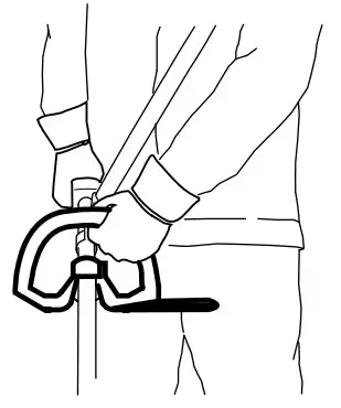
- Now press the clamping shell 4b of the round handle 4 onto the rubber ring 4a of the boom 7 from below.
- Insert the locking screw and tighten it.
Fitting the quick release mechanism
- Hook in the carabiner and secure it with the red strap on the quick release mechanism (see illustrations). Pull on the red strap if you have to release the tool quickly.
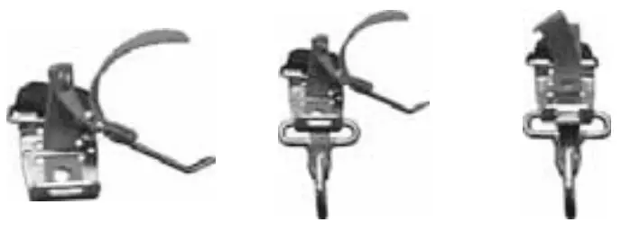
Securing/attaching the carrying harness
- Hook the carrying harness 57 into the carrying lug 3.
- Adjust the carrying harness 57 to your size so that the carrying lug 3 is at hip height when the strap is hooked in place.
Fitting the hedge trimmer
- First, undo the locking screw 6 on the boom 7 of the engine unit.
- Push the pin on the front boom 27 of the hedge trimmer into the opening on the boom 7 on the engine unit as far as the stop. You have to make sure that the spring-loaded ball engages in the hole provided.
- Tighten the locking screw 6.
NOTE
The assembly for the pole pruner/strimmer/3-tooth cutting blade/ extension attachment is done in the same order.
Removing the hedge trimmer
- Undo the locking screw 6 and pull the front boom 22 of the hedge trimmer out of the boom 7 on the engine unit.
Note; Dismantling the pole pruner/strimmer/3-tooth cutting blade/extension attachment is done in the same order.
Swivelling the hedge trimmer
- Release the lock/release 17.
- Press the control lever 21 and swivel the hedge trimmer into the desired position.
WARNING
- The cutter bar 19 must not be pivoted completely backwards parallel to the front boom 22 in order to work with it. There is a risk of injury! This position only serves as a transport position.
- Allow the control lever 21 to click into the recess in the base plate (hedge trimmer) 20.
Mounting the saw chain and blade
WARNING
Wear protective gloves! There is a risk of injury from the sharp cutting teeth
NOTE
Pay close attention to the running direction of the saw chain 30 on the blade 29 and at the base plate (hedge trimmer)  .
.
Depending on wear, the blade 29 can be turned.
- Undo the nut 35 using the spark plug wrench 64.
- Remove the sprocket cover 37.
- Place the saw chain 30 around the blade 29 starting at the tip.
- Now fit the blade 29 and saw chain 30.
- Lay the guide rail 40 over the blade guide 38, while inserting the chain tensioner pin 44 in the blade hole 39. At the same time, lay the saw chain 30 over the chain sprocket 42.
- Now you can tighten the saw chain 30(see section “Tightening and checking the saw chain”).
- Replace the sprocket cover 37 and tighten the nut 35 firmly
Removing the saw chain
- You may have to loosen the saw chain 30 to remove the blade 29 and the saw chain 30 (see section “Tightening and checking the saw chain”). Follow these instructions in reverse order.
Tightening and checking the saw chain
WARNING
Wear protective gloves! There is a risk of injury from the sharp cutting teeth.
- Turn the chain tensioning screw 45 clockwise using the flat-blade screwdriver 64 to increase the tension.
- The saw chain 30 must lie against the underside of the blade. Check whether the saw chain 30 can be drawn by hand over the blade 29.
NOTE
A new saw chain 30 stretches and must be tightened more regularly
Chain lubrication
- Remove the oil filler cap 27.
- Fill the oil tank with approx. 100 ml of organic chain oil 60.
- The chain 28 lubrication can be increased or decreased using the oil adjusting screw 43.
- Press and then turn the oil adjusting screw 43 clockwise to decrease the chain lubrication.
- Press and then turn the oil adjusting screw 43 anticlockwise to increase the chain lubrication.
WARNING
Never work without chain lubrication!
If the saw chain runs dry, the cutting equipment may become irreparably damaged within a short time. Always check chain lubrication and oil level in the tank before starting work
NOTE
Use only saw chain oil, preferably biodegradable. Do not use waste oil, motor oil, etc.
While working, check whether the chain lubrication is working correctly.
Sharpening the saw chain
NOTE
- A bench grinder can be attached to the grinder support 31 for a secure grip during grinding.
- You will find detailed information on sharpening in a sharpening set, e.g. from Oregon.
- Alternatively, you can use an electrical saw chain sharpening device and follow the instructions of the manufacturer.
- If you have any doubts about carrying out the work, the saw chain should be replaced.
Assembling the extension attachment
ATTENTION
- Do not use the extension attachment/boom 53 in combination with the 3-tooth cutting blade/strimmer attachment!
NOTE
Use the extension attachment/boom 53 for working at greater heights
- Fit the extension attachment/boom 53 between the engine unit and the hedge trimmer or the pole pruner. The assembly is carried out in the same manner as previously described for the attachments.
Fitting/removing the protective guard
WARNING
- When working with the 3-tooth cutting blade 48, the protective guard 47 must be fitted. The protective guard 47 is positioned under the metal panel of the boom 50. The protective guard 47 can now be attached to the front boom 50 with 4 screws 46 . Use the supplied hex key 63 to do this (see fig. 2a–2c).
Cutting equipment
3-tooth cutting blade 48
Strimmer 49
Protective equipment
Protective guard 47
Protective guard 47+ cutting filament
protective guard C
WARNING
Do not use any other cutting equipment apart from that which is supplied with the product. The use of any other cutting equipment or protective equipment is deemed to be improper and carries a significant risk of accidents
Installing/replacing the cutting blade
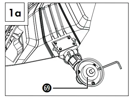
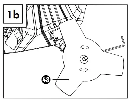
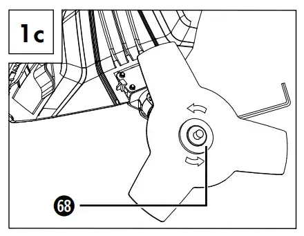
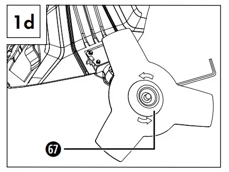
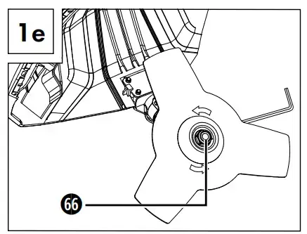
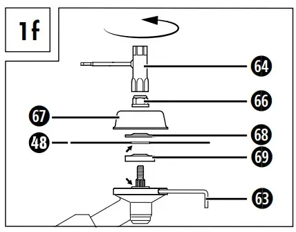
- Fit/remove the 3-tooth cutting blade 48 as shown in figures 1a–1f. ATTENTION! Left-hand thread!
- Find the hole in the drive plate 69, align it with the adjacent hole and block it with the supplied hex key 63.
- Place the 3-tooth cutting blade 48 on the drive plate 69 (see Fig. 1b). The inscription must be visible from above when holding the tool in the working position (see fold-out page). Both sides of the 3-tooth cutting blade 48 can be used.
- Fit the pressure plate 68 over the thread on the splined shaft (see Fig. 1c).
- Fit the pressure plate cover 67(see Fig. 1d).
- Tighten the nut 66 with the spark plug wrench 64 anticlockwise. ATTENTION! Left-hand thread! (see Fig. 1f).
- The 3-tooth cutting blade 48 is fitted with a plastic cover on delivery. It must be removed before use and refitted during periods when the tool is not in use.
- The plastic cover can now be removed
ATTENTION! SHARP EDGES, WEAR PROTECTIVE GLOVES!
- Fit the cutting filament protective guard C on the protective guard 47.
- The cutting filament protective guard C must be fitted when working with the cutting filament. The cutting filament protective guard C (pre-fitted on delivery) is fitted as shown in figure 2a.
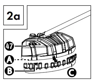
- Ensure that the cutting filament protective guard C is correctly clicked into place. There is a blade A on the inside of the cutting filament protective guard C . It is protected with a safety cover B (see Figs. 2a and 2b).
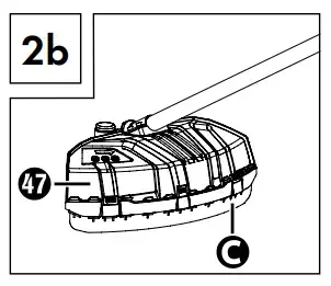
- Remove the safety cover B before starting work and replace it after finishing work.
ATTENTION! SHARP EDGES, WEAR PROTECTIVE GLOVES!
To remove the cutting filament protective guard C from the protective
guard 47, take a tool, such as a screwdriver, to carefully remove the three mounting pins. ATTENTION! RISK OF INJURY!
Installing/replacing the strimmer
- Install/replace the strimmer 69 as shown in figure 2c. ATTENTION! Left-hand thread!
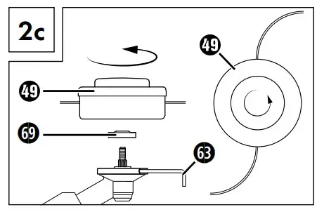
- Find the hole in the drive plate 69, align it with the adjacent hole and block it with the supplied hex key 63.
- Screw the strimmer 49 anticlockwise onto the thread.
Putting on the carrying harness

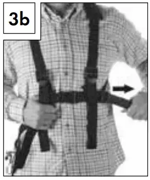
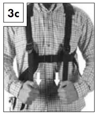
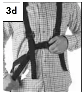
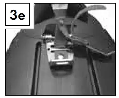
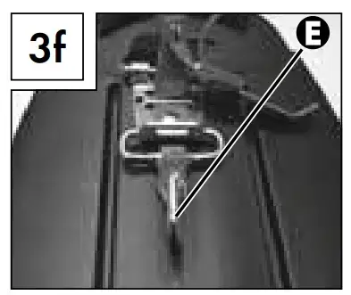
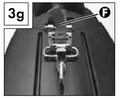
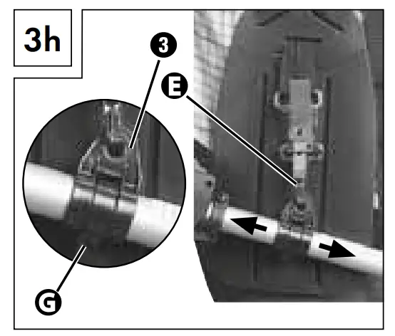
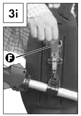
NOTE
- The following adjustments can be made to make sure that you can work without becoming fatigued. The settings may vary depending on your body size.
- Before starting work, adjust the carrying harness 57 to fit your body size.
- Balance the tool with the fitted cutting tool so that the cutting tool swings just above the ground without the need to move the tool with
your hands.
- Put on the carrying harness 57 and close the clasp so that it clicks into place (see Fig. 3a).
- As shown in figure 3b, pull on the belt 57 to position the carrying harness 57 centrally on your body and adjust the upper body sizeas required.
- To tighten the two shoulder straps, pull on the two shoulder straps as shown in figure 3c.
- To ensure to the correct position of the tool on the carrying harness, pull the belt as shown in figure 3d.
- Hook in the carabiner E (see Figs. 3e–3g) and secure it with the red strap F on the quick release mechanism.
- Now take the tool and hang it so that the carrying lug 3 clicks into the carabiner E as shown in figure 3h. The carrying lug 3 can also be moved by loosening the screw G and sliding it to achieve optimum orientation of the tool.
Setting the cutting height

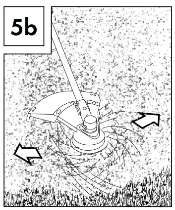
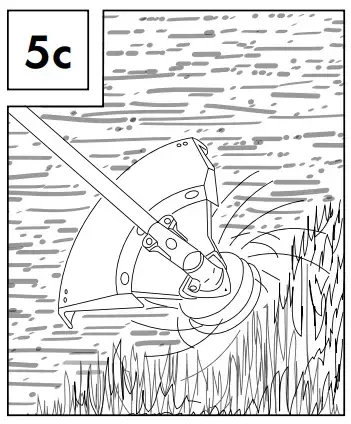
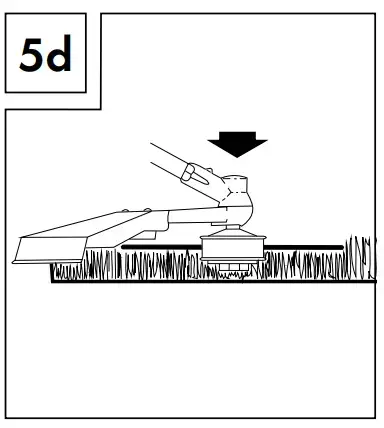
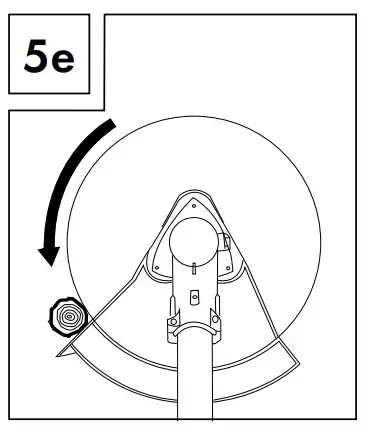
- Put on the carrying harness 57 and hook the tool (see section “Putting on the carrying harness”).
- Use the various adjusting straps on the carrying harness 57 to adjust the optimum working and cutting position (see section “Putting on the carrying harness”).
- Perform a few circular movements without starting the engine in order to find the ideal carrying strap length (see Fig. 5a).
- The carrying harness 57 is equipped with a quick release mechanism. Pull on the red strap F if you have to release the tool quickly (see Fig. 3i)
ATTENTION
- Always use the carrying harness 57 when working with the tool. Put on the carrying harness 57 as soon as you have started the engine and it is idling. Switch off the engine before removing the carrying harness 57.
Fuel and oil
- Only use a mixture of unleaded petrol (at least RON 95) and special 2-stroke engine oil (JASO FD/ISO-L-EGD). Mix the fuel mixture in accordance with the fuel mix table.
- Add the respective correct amounts of unleaded petrol and 2-stroke oil to the supplied oil/petrol mixing canister 61 (see “Fuel mix table”). Then shake the canister well.
Fuel mix table
Fuel mix table
Mixing ratio: 40 parts petrol to 1 part oil
Petrol: 0.5 litres
2-stroke oil: 12.5 m
Use
ATTENTION
Please pay attention to the statutory provisions in the relevant noise protection regulations.
Before starting the tool, always check that:
- The fuel system is not leaking.
- The protective equipment and cutting equipment is complete and in perfect working order.
- All screw connections are firmly tightened.
- All moving parts can move smoothly and freely.
Starting when the engine is cold
ATTENTION
Never allow the starter pull cord to whip back. This could cause damage.
- Fill the petrol tank 12 using the funnel 71 (see also the section “Fuel and oil”).
- Push the fuel pump (primer)14 6 times.
- Pull the choke lever 10 into the position “ ”.
- Hold the tool firmly and pull out the starter pull cord 11 to the point of first resistance. Now pull hard on the starter pull cord 11. The tool starts.
- If the engine does not start, repeat steps 1-4.
- As soon as the engine is running, first press the safety lock-out 1 and then the throttle 8 to activate the automatic choke. If the engine does not start after several attempts, see the section “Troubleshooting”
ATTENTION
Always pull the starter pull cord 11 straight out. Hold the handle of the starter pull cord 11 firmly when the starter pull cord 11 retracts. Do not allow the starter pull cord 11 to whip back.
NOTE
At very high ambient temperatures, it is possible that even a cold engine has to be started without using the choke!
Starting when the engine is hot
(The tool has been shut down for less than 15–20 minutes)
- The choke lever 10 does not need to be pulled out to start a warm engine.
- Hold the tool firmly and pull out the starter pull cord 11 to the point of first resistance. Now pull hard on the starter pull cord . The tool should start after 1–2 pulls. If the tool still has not started after 6 pulls, repeat steps 1–4 from the section “Starting when the engine is cold”.
Switching the engine off
Emergency stop sequence
If you need to stop the tool immediately, push the On/Off switch forwards
Normal sequence
- Release the throttle lever 8 and wait until the engine has slowed down to its idling speed. Then push the On/Off switch 2 forwards.
ATTENTION
The 3-tooth cutting blade must be stationary when the engine is idling. If the 3-tooth cutting blade is turning, adjust the carburettor!
Working procedures
Before using the tool, practice all working techniques (see Figs. 5a–5c) with the engine stopped.
Extending the cutting filament
To extend the cutting filament, run the engine at full speed and tap the strimmer on the floor. The filament extends automatically. The blade A on the cutting filament protective guard C cuts the thread to an appropriate length (see Fig. 5d).
ATTENTION
Grass/weed residues can get caught under the protective guard .
Switch the engine off and remove the residue using a scraper or similar item.
Various
Trimming/mowing (3-tooth cutting blade or strimmer)
- Swing the tool in a scything motion (see Fig. 5a).
- Hold the cutting tool parallel to the floor and set the desired cutting height
Low trimming (with strimmer)
- Hold the tool at a slight angle to the ground (see Fig. 5b). Always cut away from your body. Never pull the tool towards you.
Short mowing (with strimmer)
- Short mowing removes all the vegetation right down to the ground. Angle the strimmer 30° to the right. Set the handle to the desired position (see Fig. 5c).
Cutting against trees/fences/foundations (with strimmer)
NOTE
- The filament will wear or fray quickly if it comes into contact with trees, rocks, walls or foundations. The filament will break off if it strikes fence mesh.
ATTENTION
Do not use the tool to remove any objects from footpaths, etc.! The tool is powerful and can fling small stones or other objects 15 metres or more and may cause injuries or damage to cars, houses and windows
 Wear safety goggles!
Seizing
Immediately switch off the engine if the cutting tool becomes blocked. Remove all grass and scrub from the tool before restarting the tool.
Prevent kickback
When working with the 3-tooth cutting blade there is a risk of kickback if the blade strikes against solid obstacles (tree trunks, branches, tree stumps, rocks or similar). It will result in the cutting tool being thrown back against the rotational direction. This can lead to losing control of the tool. Do not use the cutting blade near fences, metal posts, boundary stones or foundations. To cut weak shrubs, position the tool as shown in Fig. 5e to avoid kickbacks.
Working with the hedge trimmer
Cutting techniques
- The double-sided cutter bar allows cutting in both directions or by using swinging movements from one side to the other.
- For a vertical cut, move the hedge trimmer evenly forwards or up and down in an arc.
- For a horizontal cut, move the hedge trimmer in a scything motion along the edge of the hedge so that cut branches fall to the ground.
- See fold-out page (figure A).
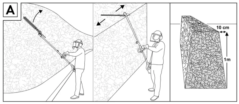
NOTE
Remove thicker branches with a branch cutter
Working with the pole pruner
Sawing techniques
WARNING
- Watch out for falling clippings.
- Be aware of the danger of branches whipping back
NOTE
- Place the stop 32 on the branch. This will help you work more safely and quietly.
- Now you can begin sawing
Sawing off small branches
Saw small branches (Ø 0–8 cm) from the top down (see figure).
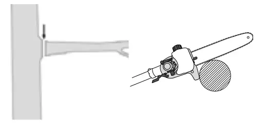
Sawing off larger branches
- Before sawing larger branches (Ø 8–25 cm), first make a relief cut A (see figure). A relief cut also prevents peeling of the bark on the main trunk.
- Saw from the top B to the bottom A
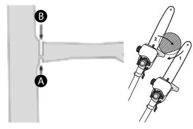
Saw in sections
Trim long or thick branches before you make the final cut (see figure).
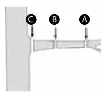
Working safely
- Keep the tool, the cutting mechanism and the chain guard in good condition to prevent injury.
- If the tool has been dropped, check for significant damage or defects.
- Observe the specified working angle max. 60°±10° to ensure safe working (see figure).
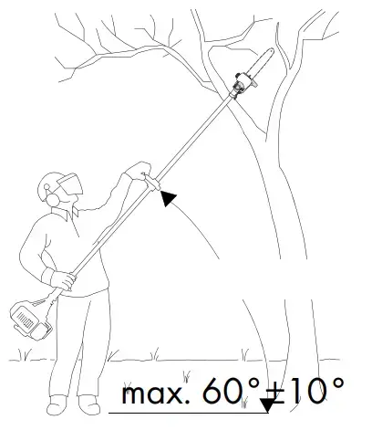
- Do not use the tool while standing on a ladder or with unsteady footing.
- Do not be tempted into making a poorly considered cut. You could endanger yourself and others.
- Children should be supervised to ensure that they do not play with the tool.
- Change your working position regularly. Using the tool for a long time can lead to vibration-related circulation disorders of the hands. You can extend the usage duration by using appropriate gloves or by taking regular breaks. Note that any personal predisposition to poor blood circulation, low external temperatures or large gripping forces can reduce the usage period
Transport
- Use the protective cases 58,59 when transporting the tool.
- To prevent injuries, ensure that the tool cannot switch on during transport (see figure)
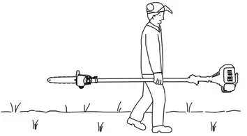
Cleaning
Cleaning the engine unit
NOTE
- Clean the tool thoroughly after every use.
- Before cleaning, always switch off the tool and disconnect the spark plug connector 9.
- Clean the tool regularly with a damp cloth and a mild detergent. Make sure that no water can penetrate into the interior of the tool.
Cleaning the pole pruner
The pole pruner must be cleaned of sawdust at regular intervals.
- Remove the sprocket cover 37.
- Remove the saw chain 30 from the blade 29 and clean the guide rail 40.
- Keep the saw chain 30 sharp and check the tension; check the oil level and the oil supply.
Cleaning the hedge trimmer
- Check the hedge trimmer for loose screws on the cutter bar 19 and tighten them, if necessary.
- Remove stuck cuttings.
- Maintain the cutter bar 19 using an oil spray or an oil can
Cleaning the strimmer/cutting blade attachment
- Remove stuck cuttings.
- Keep the 3-tooth cutting blade 48 sharp to facilitate your work
Maintenance
Replacing the strimmer/cutting filament
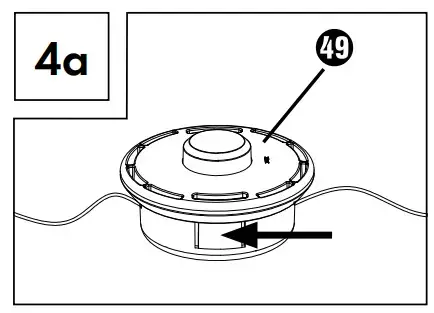
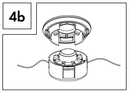
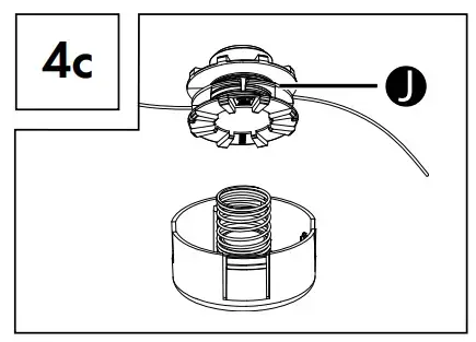
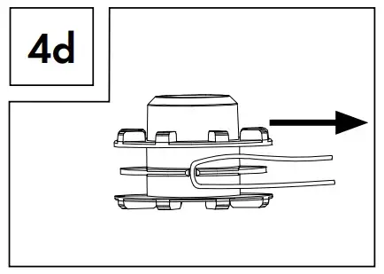

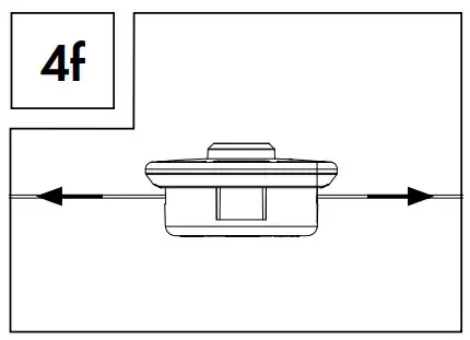
- The strimmer must be removed as described in section “Installing/ replacing the strimmer”. Press the marking (see Fig. 4a) and remove the cover (see Fig. 4b).
- Remove the spool bobbin from the strimmer housing (see Fig. 4c).
- Remove any remaining cutting filament.
- Double the new cutting filament and hook the loop that you have made into the recess on the spool bobbin (see Fig. 4d).
- Wind the filament tightly in an anticlockwise direction. The spool bobbin separates the two halves of the cutting filament (see Figs.4e and 4f).
- Now take the cover in your hand and place the spool bobbin in it.Make sure that the filament holder of the spool bobbin lines up with the filament guide on the cover.
- Now release the cutting filament from the spool bobbin and guide it through the metal eyes in the cover.
- Put the two halves of the housing back together until they click into place.
- Cut any excess filament back to about 13 cm. This reduces the load on the engine during start-up and while warming up.
- Refit the strimmer (see section “Installing/replacing the strimmer”).
Air filter maintenance
Contaminated air filters reduce engine performance due to low air supply
to the carburettor.
Regular inspection is essential. The air filter must be inspected after every 25 hours of operation and cleaned if necessary.
The air filter must be checked more frequently if you are working in dusty environments.
- Remove the cover of the air filter housing .
- Remove the air filter.
- Clean the air filter by tapping or blowing it out (with compressed air).
- Assembly is done in the reverse order.
ATTENTION
Never clean the air filter with petrol or flammable solvents.
Spark plug maintenance
- Pull off the spark plug connector 9.
- Unscrew the spark plug using the supplied spark plug wrench 64
- Assembly is done in the reverse order
Electrode gap = 0.6 mm (distance between the electrodes between which the ignition spark is generated). Check the spark plug for contamination after the first 10 hours of operation and clean it with a copper wire brush, if required.
Afterwards, service the spark plug after every 50 hours of operation.
Grinding the protective guard blade
The blade A (see Fig. 2a) can become blunt over time. If you notice this has happened, undo the 2 screws that hold the blade A onto the cutting filament protective guard C . Clamp the blade A in a vice. Grind the blade A with a sharpening stone and make sure you maintain the angle of the cutting edge
Adjusting the carburettor
Carburettor adjustments should only be carried out by qualified personnel, the manufacturer or its service department
Lubricating the gears
Add gear grease after every 20 hours of operation (approx. 10 g) to lubricate the angle gear.
- To do this, undo the screw D (see fold-out page) to press the gear grease into the gearbox casing.
- After filling the gearbox, close the lubrication hole with the screw D.
Storage and transportation
- Store the tool in a safe location.
- Store the tool and accessories in a safe location that is protected against naked flames and sources of heat/sparks, such as gas-powered water heaters, dryers, oil stoves or mobile heaters, etc.
- Ensure that the protective guard 47, the strimmer 49 and the engine are free of cutting residue during storage.
- The plastic cover for the 3-tooth cutting blade 48 must be refitted for transport and storage.
- Always switch the tool off before performing any maintenance work and remove the spark plug connector 9.
Storing the tool
The tool must be prepared for storage if it is to be stored for longer than 30 days. Otherwise the residual fuel in the carburettor will evaporate and leave a gooey sediment. This may make starting the tool more difficult and result in expensive repair work.
- Remove the filler cap 13 to relieve any pressure in the petrol tank 12. Carefully empty the petrol tank 12.
- To remove all fuel from the carburettor, start the engine and let it run until it stops.
- Allow the engine to cool for about 10 minutes.
- Remove the spark plug (see section “Spark plug maintenance”).
- Add 1 teaspoon of 2-stroke oil to the combustion chamber. Pull the starter pull cord 11 several times to wet all mechanical parts with oil. Replace the spark plug.
NOTE
Store the tool in a dry place and away from possible ignition sources
Start-up after storage
- Remove the spark plug (see section “Spark plug maintenance”).
- Pull the starter pull cord 11 quickly in order to remove any excess oil from the combustion chamber.
- Clean the spark plug and observe the correct electrode gap on the spark plug.
- Fill the petrol tank 12. See the section “Fuel and oil”
Transport
- If you are planning on transporting the tool, empty the petrol tank as explained in the section “Storage”.
Troubleshooting
Engine unit
| Problem | Possible cause | Troubleshooting | ||
| The engine does not start. | Incorrect start-up process. | Follow the instructions
regarding starting. |
||
| The engine starts but does not run at full power. | Incorrect adjustment of the choke lever . | Set the choke lever | ||
| to “ | “. | |||
| Contaminated air filter. | Clean air filter. | |||
| The engine does not run smoothly. | Incorrect spark plug gap. | Clean the spark plug and adjust the spark plug gap or replace the spark plug. | ||
| Soot deposits or wetness on the spark plug. | Incorrect carburettor adjustment. | Clean the spark plug or replace it with a new spark plug. | ||
Pole pruner
| Problem | Possible cause | Troubleshooting |
| Engine is running, saw
chain does not move. |
Hedge trimmer attachment or pole pruner attachment is not connected properly to the engine unit. | Check assembly. |
|
No progress. |
Saw chain is dry/over- heating or is sagging. |
Top up the oil and regrind, replace or tighten the saw
chain . |
Hedge trimmer
| Problem | Possible cause | Troubleshooting |
| Engine is run- ning, blades do not move. | Hedge trimmer attachment or pole pruner attachment is not connected properly to the engine unit. | Check assembly. |
Maintenance intervals
Pole pruner
The figures given here are based on normal operating conditions. In difficult conditions, e.g. heavy dust formation and longer daily working hours, the specified intervals must be shortened accordingly.
| Tool part | Action | Before starting work | Weekly | In the event of an error | In the event of dam- age | As re- quired |
| Chain lubrica- tion | Check | X | ||||
| Saw chain 30 | Check and note sharpness | X | ||||
| Check chain tension | X | |||||
| Sharpen | X | |||||
| Guide rail 40 | Check (wear, damage) | X | ||||
| Clean and turn | X | X | ||||
| Deburr | X | |||||
| Replace | X | X | ||||
| Chain sprocket 42 | Check | X | ||||
| Replace | X |
Hedge trimmer
The figures given here are based on normal operating conditions. In difficult conditions, e.g. heavy dust formation and longer daily working hours, the specified intervals must be shortened accordingly.
| Tool part | Action | Before starting work | After finishing work | As required |
| Cutting blade | Visual inspection | X | ||
| Cleaning | X | X |
Ordering replacement parts
Ordering spare parts
The following information should be provided when ordering spare parts:
- Type of tool
- Item number of the tool
- Device ID number
Current prices and information are available at
NOTE Replacement parts that are not listed (e.g. strimmer, cutting filament) can be ordered via our service hotline.
Disposal
 The packaging for this product is made from environmentally friendly material and can be disposed of at your local recycling plant. The device and its accessories are made from various materials, such as metal and plastic. Your local community or municipal authorities can provide information on how to dispose of the worn-out tool.
Dispose of the packaging in an environmen tally friendly manner.
Note the labelling on the packaging and separate the packaging material components for disposal if necessary. The packaging material is labelled with abbreviations (a) and numbers (b) with the following meanings: 1–7: plastics, 20–22: paper and cardboard, 80–98: composites.
Your local community or municipal authorities can provide information on how to dispose of the worn-out product.
Environmental protection
- Carefully empty the petrol and oil tank and dispose of your tool at a recycling plant. The used plastic and metal parts can be separated and recycled.
- Dispose of waste oil and petrol at a waste collection centre and do not dump them into the sewerage or drainage system.
- Dispose of contaminated maintenance material and consumables at a collection point provided for this purpose.
Kompernass Handels GmbH warranty
Dear Customer,
This appliance has a 3-year warranty valid from the date of purchase. If this product has any faults, you, the buyer, have certain statutory rights. Your statutory rights are not restricted in any way by the warranty described below.
Warranty conditions
The warranty period starts on the date of purchase. Please keep your receipt in a safe place. This will be required as proof of purchase. If any material or manufacturing fault occurs within three years of the date of purchase of the product, we will either repair or replace the product for you or refund the purchase price (at our discretion). This warranty service requires that you present the defective appliance and the proof of purchase (receipt) within the three-year warranty period, along with a brief written description of the fault and of when it occurred. If the defect is covered by the warranty, your product will either be repaired or replaced by us. The repair or replacement of a product does not signify the beginning of a new warranty period.
Warranty period and statutory claims for defects
The warranty period is not prolonged by repairs effected under the warranty. This also applies to replaced and repaired components. Any damage and defects present at the time of purchase must be reported immediately after unpacking. Repairs carried out after expiry of the warranty period shall be subject to a fee.
Scope of the warranty
This appliance has been manufactured in accordance with strict quality guidelines and inspected meticulously prior to delivery.
The warranty covers material faults or production faults. The warranty does not extend to product parts subject to normal wear and tear or to fragile parts which could be considered as consumable parts such as switches or parts made of glass.
The warranty does not apply if the product has been damaged, improperly used or improperly maintained. The directions in the operating instructions for the product regarding proper use of the product are to be strictly followed. Uses and actions that are discouraged in the operating instructions or which are warned against must be avoided.
This product is intended solely for private use and not for commercial purposes. The warranty shall be deemed void in cases of misuse or improper handling, use of force and modifications / repairs which have not been carried out by one of our authorised Service centres.
The warranty period does not apply to
- Normal reduction of the battery capacity over time
- Commercial use of the product
- Damage to or alteration of the product by the customer
- Non-compliance with safety and maintenance instructions, operating errors
- Damage caused by natural hazards
Warranty claim procedure
To ensure quick processing of your case, please observe the following instructions:
- Please have the till receipt and the item number (e.g. IAN 12345) available as proof of purchase.
- You will find the item number on the type plate on the product, an engraving on the product, on the front page of the operating instructions (below left) or on the sticker on the rear or bottom of the product.
- If functional or other defects occur, please contact the service department listed either by telephone or by e-mail.
- You can return a defective product to us free of charge to the service address that will be provided to you. Ensure that you enclose the proof of purchase (till receipt) and information about what the defect is and when it occurred.
You can download these instructions along with many other manuals, product videos and installation software at www.lidl-service.com.
This QR code will take you directly to the Lidl service page
(www.lidl-service.com) where you can open your operating instructions by entering the item number (IAN) 352083_2007.
WARNING!
Have your tool repaired by qualified specialists only. Always use original spare parts. This will ensure that the safety of the tool is maintained.
Service
Service Great Britain
Tel.: 0800 404 7657
E-Mail: [email protected]
Service Ireland
Tel.: 1890 930 034
(0,08 EUR/Min., (peak))
(0,06 EUR/Min., (off peak))
E-Mail: [email protected]
IAN 352083_2007
Importer
Please note that the following address is not the service address. Please use the service address provided in the operating instructions.
KOMPERNASS HANDELS GMBH
BURGSTRASSE 21
44867 BOCHUM
GERMANY
www.kompernass.com
Original declaration of conformity
We, KOMPERNASS HANDELS GMBH, document officer: Mr Semi Uguzlu,
BURGSTR. 21, 44867 BOCHUM, GERMANY, hereby declare that this tool complies with the following standards, normative documents and EC directives:
2006/42/EC)
Compliance in accordance with Annex IV of 2006/42/EC
Notification body
TÜV SÜD Product Service GmbH,
Ridlerstrαβe 65, 80339 München, Deutschland (0123)
Certification number: M6A 030574 2373 Rev.01
Electromagnetic compatibility
(2014/30/EU)
Outdoor Noise Directive
(2005/88/EC)
(2000/14/EC)
Emissions directive
2016/1628/EU (modified by the last 2017/656/EU)
RoHS Directive
(2011/65/EU)*
The manufacturer bears sole responsibility for issuing this declaration of conformity. The subject of the declaration described above meets the requirements of Directive 2011/65/EU of the European Parliament and Council of 8 June 2011 on the limitations of use of certain dangerous substances in electrical and electronic tools.
Applied harmonised standards
EN ISO 11806-1:2011
EN ISO 10517: 2019
EN ISO 11680-1:2011
EN ISO 14982:2009
EN 50581:2012
Type/tool designation: 4-in-1 Petrol Multi-Tool PBK 4 A2
Year of manufacture: 10 – 2020
Serial number: IAN 352083_2007
Bochum, 27/10/2020

Semi Uguzlu
– Quality Manager –
We reserve the right to technical changes in the context of further product
development.
COMPRESSOR PKO 24 B2

COMPRESSOR
Operating and Safety Instructions
Translation of Original Operating Manual
IAN 360588_2010

Before reading, unfold the page containing the illustrations and familiarise yourself with all functions of the device.
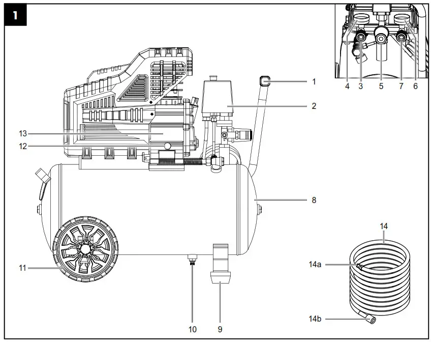
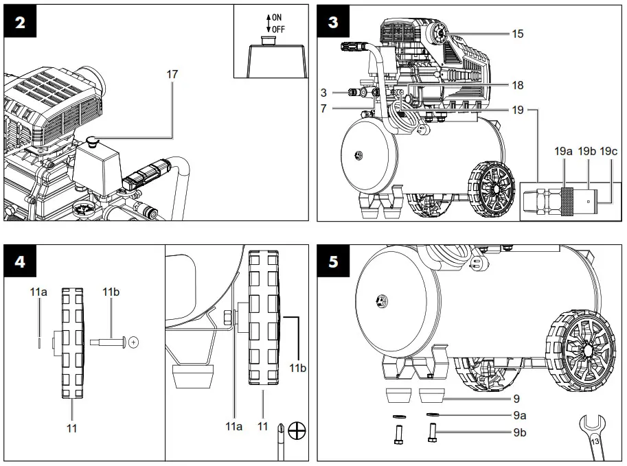
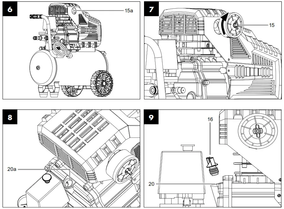
Explanation of the symbols on the device
| Read the operating and safety instructions before start-up and follow them! | |
| Wear hearing protection. Excessive noise can result in a loss of hearing. | |
| Warning against hot parts! (A fig. 11) | |
 |
Warning against electrical voltage |
 |
Warning! The equipment may start automatically without warning. |
 |
Attention! Prior to initial commissioning, check the oil level and replace the oil sealing plug! |
| Observe warnings and safety instructions! | |
 |
Sound power level specified in dB |
 |
Do not expose the device to rain! |
Introduction
Manufacturer:
scheppach
Fabrikation von Holzbearbeitungsmaschinen GmbH
Günzburger Straße 69
D-89335 Ichenhausen
Dear customer,
We hope your new tool brings you much enjoyment and success.
Note:
In accordance with the applicable product liability laws, the manufacturer of this device assumes no liability for damage to the device or caused by the device arising from:
- Improper handling,
- Non-compliance with the operating manual,
- Repairs carried out by third parties, unauthorised specialists.
- Installing and replacing non-original spare parts,
- Application other than specified,
- Failures of the electrical system in the event of the electrical regulations and VDE provisions 0100, DIN 57113 / VDE 0113 not being observed.
Please consider:
Read through the complete text in the operating manual before installing and commissioning the device. This operating manual should help you familiarise yourself with your power tool and teach you how to use it for its intended purpose. The operating manual includes important instructions for the safe, proper and economic operation of the machine, for avoiding danger, for minimising repair costs and downtimes and for increasing the reliability and extending the service life of the machine. In addition to the safety instructions in this operating manual, you must also observe the regulations applicable to the operation of the machine in your country. Keep the operating manual package with the power tool at all times and store it in a plastic cover to protect it from dirt and moisture. They must be read and carefully observed by all operating personnel before starting the work. The power tool may only be used by personnel who have been trained to use it and who have been instructed with respect to the associated hazards. The required minimum age must be observed. In addition to the safety instructions in this operating manual and the separate regulations of your country, the generally recognised technical rules relating to the operation of such machines must also be observed. We accept no liability for accidents or damage that occur due to a failure to observe this manual and the safety instructions.
Device description (fig. 1-12)
| 1. Transport handle | 14. Compressed air hose |
| 2. Pressure switch | 14a. Plug nipple |
| 3. Quick coupling (regulated compressed air) | 14b. Quick coupling |
| 4. Pressure gauge (set pressure can be read off) | 15. Air filter |
| 5. Pressure regulator | 15a. Transport lid |
| 6. Pressure gauge (vessel pressure can be read off) | 15b. Wing screw |
| 7. Quick coupling (unregulated compressed air) | 15c. Filter element |
| 8. Pressure vessel | 15d. Filter housing |
| 9. Supporting foot | 15e. Filter cover |
| 9a. Washer | 16. Oil sealing plug |
| 9b. Screw | 17. On/off switch |
| 10. Drain screw for condensate | 18. Oil-level window |
| 11. Wheel | 19. Safety valve |
| 11a. Washer | 19a. Exhaust nut |
| 11b. Fillister head screw | 19b. Connection lock |
| 12. Oil drain screw | 19c. Cap of exhaust nut |
| 13. Compressor pump | 20. Oil filling opening |
| 20a. Transport lid |
Scope of delivery
- 1x air filter
- 2x supporting foot
- 2x wheel
- 1x assembly material
- 1x oil sealing plug
- 1x oil bottle
- 1x compressed air hose
- 1x operating manual
Proper use
The compressor is designed to generate compressed air for compressed-air driven tools which can be driven with an air volume of up to approx. 180 l/min (e. g. tire inflator, blow-out pistol and paint spray gun). Due to the limited air output it is not possible to use the compressor to drive tools with very high air consumption (for example orbital sanders, die grinders and hammer screwdrivers).
The machine may only be used in the intended manner. Any use beyond this is improper. The user/operator, not the manufacturer, is responsible for damages or injuries of any type resulting from this. Please observe that our equipment was not designed with the intention of use for commercial or industrial purposes. We assume no guarantee if the equipment is used in commercial or industrial applications, or for equivalent work.
Safety information
 Attention! The following basic safety measures must be observed when using power tools for protection against electric shock, and the risk of injury and fire. Read all these notices before using the power tool and store the safety instructions well for later reference.
Safe work
- Keep the work area orderly
– Disorder in the work area can lead to accidents. - Take environmental influences into account
– Do not expose power tools to rain.
– Do not use power tools in a damp or wet environment.
There is a risk of electric shock!
– Make sure that the work area is well-illuminated.
– Do not use power tools where there is a risk of fire or explosion. - Protect yourself from electric shock
– Avoid physical contact with earthed parts (e. g. pipes, radiators, electric ranges, cooling units). - Keep away from children!
– Do not allow other persons to touch the equipment or cable, keep them away from your work area. - Securely store unused power tools
– Unused power tools should be stored in a dry, elevated or closed location out of the reach of children. - Do not overload your power tool
– They work better and more safely in the specified output range. - Wear suitable clothing
– Do not wear wide clothing or jewellery, which can become entangled in moving parts.
– Rubber gloves and anti-slip footwear are recommended when working outdoors.
– Tie long hair back in a hair net. - Do not use the cable for purposes for which it is not intended
– Do not use the cable to pull the plug out of the outlet.
Protect the cable from heat, oil and sharp edges. - Take care of your tools
– Keep your compressor clean in order to work well and safely.
– Follow the maintenance instructions.
– Check the connection cable of the power tool regularly and have it replaced by a recognised specialist when damaged.
– Check extension cables regularly and replace them when damaged. - Pull the connector out of the socket
– When the power tool is not in use or prior to maintenance and when replacing tools such as saw blades, bits, milling heads. - Avoid inadvertent starting
– Make sure that the switch is switched off when plugging the plug into an outlet. - Use extension cables for outdoors
– Only use approved and appropriately identified extension cables for use outdoors.
– Only use cable reels in the unrolled state. - Always remain attentive
– Pay attention to what you are doing. Remain sensible when working. Do not use the power tool when you are distracted. - Check the power tool for potential damage
– Protective devices or other parts with minor damage must be carefully inspected to ensure that they function correctly and as intended prior to continued use of the power tool.
– Check whether the moving parts function faultlessly and do not jam or whether parts are damaged. All parts must be correctly mounted and all conditions must be fulfilled to ensure fault-free operation of the power tool.
– Damaged protective devices and parts must be properly repaired or replaced by a recognised workshop, insofar as nothing different is specified in the operating manual. – Damaged switches must be replaced at a customer service workshop.
– Do not use any faulty or damaged connection cables.
– Do not use any power tool on which the switch cannot be switched on and off. - Have your power tool repaired by a qualified electrician
– This power tool conforms to the applicable safety regulations. Repairs may only be performed by an electrician using original spare parts. Otherwise accidents can occur. - Attention!
– For your own safety, only use accessories and additional equipment that are indicated in the operating manual or have been recommended or indicated by the manufacturer. Use of other tools or accessories that those recommended in the operating manual or in the catalogue could represent a personal danger to you. - Noise
– Wear hearing protection when using the compressor. - Replacing the connection line
– If the connection line is damaged, it must be replaced by the manufacturer or an electrician to avoid danger. There is a risk of electric shock. - Inflating tyres
– Directly after inflating tyres, check the pressure with a suitable pressure gauge, for example at your filling station. - Street-legal compressors in construction site operation
– Ensure that all hoses and fixtures are suitable for the maximum permissible working pressure of the compressor. - Set-up location
– Only set up the compressor on a flat surface. - In case of pressures above 7 bar, it is recommended to equip supply hoses with a safety cable (e. g. a wire rope).
- Avoid over-stressing the piping system by using flexible hose connections to prevent kinking.
- Ensure that oil cooling devices are kept clean and protective devices remain in operational condition.
- Risk of burns from hot oil
– Wear suitable protective gloves.
– Never work with the compressor near naked flames.
– Be careful not to spill oil. - Motor start-up is prohibited at low temperatures below 0 °C.
Additional safety instructions
Safety instructions for working with compressed air and blasting guns
- The compressor pump and lines can become very hot during operation. Touching these parts will burn you.
- The air which is sucked in by the compressor must be kept free of impurities that could cause fires or explosions in the compressor pump.
- When releasing the hose coupling, hold the hose coupling piece with your hand. This way, you can protect yourself against injury from the rebounding hose.
- Wear safety goggles when working with the blow-out pistol. Foreign bodies or blown off parts can easily cause injuries.
- Do not blow at people with the blow-out pistol and do not clean clothes while being worn. Danger of injury!
Safety information for paint spraying
- Do not process any paints or solvents with a flash point below 55° C. Risk of explosion!
- Do not heat up paints or solvents. Risk of explosion!
- If hazardous liquids are processed, wear protective filter units (face guards). Also, adhere to the safety information provided by the manufacturers of such liquids.
- The details and designations of the Ordinance on Hazardous Substances, which are displayed on the outer packaging of the processed material, must be observed. Additional protective measures are to be undertaken if necessary, particularly the wearing of suitable clothing and masks.
- Do not smoke during the spraying process and/or in the work area. Risk of explosion! Paint vapours are easily combustible.
- Never set up or operate the equipment in the vicinity of a fire place, open lights or sparking machines.
- Do not store or eat food and drink in the work area. Paint vapours are harmful to your health.
- The work area must exceed 30 m³ and sufficient ventilation must be ensured during spraying and drying.
- Do not spray against the wind. Always adhere to the regulations of the local police authority when spraying combustible or hazardous materials.
- Do not process media such as white spirit, butyl alcohol and methylene chloride with the PVC pressure hose. These media will destroy the pressure hose.
- When used in conjunction with spray accessories (e. g. a paint spray gun): Keep distance to the device while filling the spray equipment and do not spray towards the compressor.
Operation of pressure vessels
- Anyone who operates a pressure vessel must keep this in good working order, operate and monitor it correctly, perform the necessary maintenance and servicing works immediately and implement safety measures as required according to the circumstances.
- The regulatory authority can instruct necessary monitoring measures in individual cases.
- A pressure vessel must not be operated if it exhibits a defect that poses a danger to personnel or third parties.
- Check the pressure vessel for rust and damage each time before use. The compressor shall not be operated if the pressure vessel is damaged or rusty. If you discover damage, please contact the customer service workshop.
Keep these safety instructions in a safe place.
Residual risks
Comply with the stipulated maintenance and safety instructions in the operating instructions.
Remain attentive at all times when working, and keep third parties at a safe distance from your work area.
Even when the device is being used properly, there will always be certain residual hazards that cannot be completely ruled out. The following potential hazards can arise due to the type and design of the device:
- Unintentional starting up of the product.
- Damage to hearing if the stipulated hearing protection is not worn.
- Dirt particles, dust etc. can get irritate the eyes or face despite wearing safety goggles.
- Inhaling swirled up particles.
Warning!
This power tool generates an electromagnetic field during operation. This field can impair active or passive medical implants under certain conditions. In order to prevent the risk of serious or deadly injuries, we recommend that persons with medical implants consult with their physician and the manufacturer of the medical implant prior to operating the power tool.
Technical data
Mains connection ………………………………………… 230 V∼ 50 Hz
Motor power ……………………………………………………….. 1800 W
Operating mode ……………………………………………………………..S1
Compressor speed ……………………………………………..2850 min-1
Pressure vessel capacity ………………………………….. approx. 24 l
Maximum operating pressure………………………. approx. 10 bar
Theoretical intake capacity ………………………approx. 260 l/min
Sound pressure level LPA…………………………………….. 72.9 dB(A)
Sound power level LWA………………………………………. 92.9 dB(A)
Uncertainty KPA/WA…………………………………………………. 2.59 dB
Protection category …………………………………………………….. IP32
Device weight …………………………………………….approx. 26.8 kg
Oil (SAE 15W 40) ………………………………………..approx. 0.25 l
Maximum altitude (above mean sea level) ……………….1000 m
The noise emission values have been determined in accordance with EN ISO 3744:1995.
Wear hearing protection.
Excessive noise can result in a loss of hearing.
Before commissioning
- Open the packaging and carefully remove the device.
- Remove the packaging material, packaging and transport safety devices (if applicable).
- Check that the delivery is complete.
- Check the device and accessory parts for transport damage.
- If possible, keep the packaging until the expiry of the warranty period.
DANGER
The device and the packaging are not children’s toys! Do not let children play with plastic bags, films or small parts! There is a danger of choking or suffocating!
Before connecting the machine, make certain that the data on the type plate matches with the mains power data.
- Prior to initial commissioning, remove the transport lid (20a) and fill the compressor pump housing with oil as described in item 9.4.
- Check the device for transport damage. Report any damage immediately to the transport company which was used to deliver the compressor.
- Install the compressor near the point of consumption.
- Avoid long air lines and supply lines (extension cables).
- Make sure that the intake air is dry and free of dust.
- Do not install the compressor in a damp or wet room.
- The compressor may only be used in suitable rooms (with good ventilation and an ambient temperature from +5°C to 40°C). There must be no dust, acids, vapours, explosive gases or inflammable gases in the room.
- The compressor is designed to be used in dry rooms. It is prohibited to use the compressor in areas where work is conducted with sprayed water.
- The oil level in the compressor pump housing must be checked before using the machine.
Attachment and operation
 Attention!
Always make sure the device is fully assembled before commissioning!
You require the following for assembly:
1x open-ended spanner 13 mm
1x Phillips screwdriver
(not included in the scope of delivery)
- Fitting the wheels (fig. 4)
♦ Fit the supplied wheels (11) as shown. - Fitting the supporting feet (fig. 5)
♦ Fit the supplied supporting feet (9) as shown. - Fitting the air filter (fig. 6, 7)
• Remove the transport lid (15a) and screw the air filter (15) to the equipment. - Filling the oil (fig. 8, 9)
• Remove the transport lid (20a) of the oil filling opening (20).
• Fill the included compressor oil into the compressor pump housing and insert the supplied oil sealing plug (16) into the oil filling opening (20). - Mains connection
• The compressor is equipped with a mains cable with protective contact plug. This can be connected to any 220 ‒ 240 V∼ 50 Hz protective contact socket, with fuse protection of at least 16 A.
• Before you use the machine, make sure that the mains voltage is the same as the operating voltage and the machine power on the rating plate.
• Long supply cables, extensions, cable reels, etc. cause a drop in voltage and can impede motor start-up.
• At low temperatures below +5°C, sluggishness may make starting difficult or impossible. - On/off switch (fig. 2)
• Pull the on/off switch (17) upwards to switch on the compressor. To switch off the compressor, press the on/off switch (17) down. - Setting the pressure (fig. 1, 3)
• Use the pressure regulator (5) to set the pressure on the pressure gauge (4).
• The pressure set can be drawn from the quick coupling (3).
• The vessel pressure can be read off at the pressure gauge (6).
• The vessel pressure is drawn from the quick coupling (7). - Setting the pressure switch (fig. 1)
• The pressure switch (2) is set at the factory.
Cut-in pressure approx. 8 bar
Cut-out pressure approx. 10 bar - Fitting the compressed air hose (fig. 1, 3)
• Connect the plug nipple (14a) of the compressed air hose (14) to one of the quick couplings (3, 7). Then attach the compressed air tool to the quick coupling (14b) of the compressed air hose (14). - Thermal protector
The thermal protector is built into the device. If the thermal protector has tripped, proceed as follows:
• Pull out the mains plug.
• Wait about two to three minutes.
• Plug the device in again.
• If the device does not start, repeat the process.
• If the device does not start again, switch the device off and on again using the on/off switch (17).
• If you have carried out all of the steps above and the device still does not work, contact our service team.
Electrical connection
The electrical motor installed is connected and ready for operation. The connection complies with the applicable VDE and DIN provisions. The customer’s mains connection as well as the extension cable used must also comply with these regulations.
- Important notes
In the event of overloading, the motor will switch itself off. After a cool-down period (time varies) the motor can be switched back on again. - Damaged electrical connection cable The insulation on electrical connection cables is often damaged. This may have the following causes:
• Pressure points, where connection cables are passed through windows or doors.
• Kinks where the connection cable has been improperly fastened or routed.
• Places where the connection cables have been cut due to being driven over.
• Insulation damage due to being ripped out of the wall outlet.
• Cracks due to the insulation ageing. Such damaged electrical connection cables must not be used and are life-threatening due to the insulation damage.
Check the electrical connection cables for damage regularly. Ensure that the connection cables are disconnected from electrical power when checking for damage.
Electrical connection cables must comply with the applicable VDE and DIN provisions. Only use connection cables of the same designation. The printing of the type designation on the connection cable is mandatory. - AC motor
• The mains voltage must be 220 – 240 V∼ 50 Hz.
• Extension cables up to 25 m long must have a cross-section of 1.5 square millimetres.
Connections and repair work on the electrical equipment may only be carried out by electricians.
Please provide the following information in the event of any enquiries:
• Type of current for the motor
• Data of machine type plate
• Data of motor type plate
Cleaning, maintenance and storage
 Attention! Pull out the mains plug before carrying out any cleaning and maintenance work! Risk of injury from electric shock!
Attention! Wait until the equipment has cooled down completely! Danger of burning!
Attention! Always depressurise the equipment before carrying out any cleaning and maintenance work! Danger of injury!
- Cleaning
• Keep the device as free of dust and dirt as possible. Rub the device clean with a clean cloth or blow it off with compressed air at low pressure.
• We recommend that you clean the device directly after every use.
• Clean the device at regular intervals using a damp cloth and a little soft soap. Do not use aggressive cleaning agents or solvents; they could attack the plastic parts of the device. Make sure that no water can penetrate the device interior.
• The hose and injection tools must be disconnected from the compressor before cleaning. The compressor must not be cleaned with water, solvents or similar. gereinigt werden. - Maintaining the pressure vessel (fig. 1)
Attention!
To ensure a long service life for the pressure vessel (8), drain off the condensate after each use by opening the drain screw (10). Release the vessel pressure first (see 11.8.1). Open the drain screw (10) by turning it counterclockwise (when looking at the screw from the bottom of the compressor) so that the condensate can be completely drained out of the pressure vessel (8).
Then close the drain screw (10) again (turn it clockwise). Check the pressure vessel (8) for rust and damage each time before use.
Do not use the compressor with a damaged or rusty pressure vessel (8). If you discover damage, please contact the customer service workshop.
Attention!
The condensate from the pressure vessel (8) will contain residual oil.
Dispose of the condensate in an environmentally friendly manner at a suitable collection point. - Safety valve (fig. 3)
The safety valve (19) has been set for the highest permitted pressure of the pressure vessel (8). It is not permitted to adjust the safety valve (19) or remove the connection lock (19b) between the exhaust nut (19a) and its cap (19c). Actuate the safety valve (19) every 30 operating hours but at least three times a year to ensure that it works when required. Turn the perforated exhaust nut (19a) counterclockwise to open it and use your hands to pull the valve rod outwards over the perforated exhaust nut (19a) to open the outlet of the safety valve (19). Now, the valve audibly releases air. Then, tighten the exhaust nut (19a) clockwise again. - Checking the oil level at regular intervals (fig. 10)
Place the compressor on a level and straight surface.
The oil level must be between the MAX and MIN marks on the oil-level window (18).
Oil change: recommended oil: SAE 15W 40 or equivalent. The original oil filling must be changed after 100 operating hours; afterwards the oil must be drained and replaced with new oil after every 500 operating hours. - Changing the oil (fig. 1, 9, 10)
Switch the motor off and unplug the mains plug from the power outlet. Remove the oil sealing plug (16). After releasing any air pressure you can unscrew the oil drain screw (12) from the compressor pump (13). To prevent the oil from running out in an uncontrolled manner, hold a small metal chute under the opening and collect the oil in a vessel. If the oil does not drain out completely, we recommend tilting the compressor slightly. When the oil has drained out, re-fit the oil drain screw (12).
Dispose of the old oil at a drop-off point for old oil. To fill in the correct quantity of oil, make sure that the compressor stands on an even surface. Fill new oil through the oil filling opening (20) until it comes up to the maximum level. This is marked with a red dot on the oil-level window (18) (fig. 10). Do not exceed the maximum filling quantity. Overfilling the equipment may result in damage. Reinsert the oil sealing plug (16) into the oil filling opening (20). - Cleaning the air filter (fig. 3, 11, 12)
The air filter (15) prevents dust and dirt being sucked in. It is essential to clean this air filter (15) after at least every 300 hours in service. A blocked air filter significantly reduces the compressor power. Remove the air filter (15) by opening the wing screw (15b). Then pull off the filter cover (15e). Now you can remove the filter element (15c) and the filter housing (15d). Carefully tap out the filter element (15c), the filter cover (15e) and the filter housing (15d). These components must then be blown out with compressed air (approx. 3 bar) and reassembled in reverse order. - Service information
With this product, it is necessary to note that the following parts are subject to natural or usage-related wear, or that the following parts are required as consumables. Wearing parts*:Air filter * may not be included in the scope of supply! - Storage
Attention!
Pull out the mains plug and ventilate the equipment and all connected pneumatic tools. Store the compressor in such a way that it cannot be used by unauthorised persons. Attention!
Store the compressor only in a dry location which is not accessible to unauthorised persons. Always store upright, never tilted! Oil may leak out!
8.1 Releasing excess pressure
Release the excess pressure by switching off the compressor and using the compressed air which is still left in the pressure vessel (8), e. g. with a compressed air tool running in idle mode or with a blow-out pistol.
Transport
Use the transport handle (1) to transport the device, and drive the compressor with it.
When lifting the compressor, note its weight (see Technical data).
Ensure that the load is well secured when transporting the compressor in a motor vehicle.
Disposal and recycling
The device is supplied in packaging to avoid transport damages. This packaging is raw material and can thus be used again or can be reintegrated into the raw material cycle. The device and its accessories are made of different materials, such as metals and plastics. Take defective components to special waste disposal sites. Check with your specialist dealer or municipal administration!

The packaging is wholly composed of environmentally-friendly materials that can be disposed of at a local recycling centre. Contact your local refuse disposal authority for more details of how to dispose of your worn-out electrical devices.
Old devices must not be disposed of with household waste!
 This symbol indicates that this product must not be disposed of together with domestic waste in compliance with the Directive (2012/19/EU) pertaining to waste electrical and electronic equipment (WEEE). This product must be handed over at the intended collection point. This can be done, for example, by returning it when purchasing a similar product or delivering it to an authorised collection point for the recycling of old electrical and electronic devices. Improper handling of waste equipment may have negative consequences for the environment and human health due to potentially hazardous substances that are often contained in electrical and electronic equipment. By properly disposing of this product, you are also contributing to the effective use of natural resources. You can obtain information on collection points for waste equipment from your municipal administration, public waste disposal authority, an authorised body for the disposal of waste electrical and electronic equipment or your waste disposal company.
Troubleshooting
| Fault | Possible cause | Remedy |
| The compressor does not start. | Mains voltage is not available. | Check the cable, mains plug, fuse and socket. |
| Mains voltage is too low. | Make sure that the extension cable is not too long. Use an extension cable with large enough wires. | |
| Outside temperature is too low. | Never operate with an outside temperature of below +5 °C. | |
| Motor is overheated. | Allow the motor to cool down. If necessary, remedy the cause of the overheating. | |
| The compressor starts but there is no pressure. | The safety valve (19) leaks. | Contact your local service centre. Only allow qualified per-sonnel to carry out repairs. |
| The seals are damaged. | Check the seals and have any damaged seals replaced by a service centre. | |
| The drain screw for condensate (10) leaks. | Tighten the screw by hand. Check the seal on the screw and replace if necessary. | |
| The compressor starts, pressure is shown on the pressure gauge, but the tools do not start. | The hose connections have a leak. | Check the compressed air hose and tools and replace if necessary. |
| A quick coupling has a leak. | Contact your local service centre. Only allow qualified personnel to carry out repairs. | |
| Insufficient pressure set on the pressure regulator (5). | Increase the set pressure with the pressure regulator. |
Warranty certificate
Dear Customer,
All of our products undergo strict quality checks to ensure that they reach you in perfect condition. In the unlikely event that your device develops a fault, please contact our service department at the address shown on this guarantee card. Of course, if you would prefer to call us then we are also happy to offer our assistance under the service number printed below. Please note the following terms under which guarantee claims can be made:
- These guarantee terms cover additional guarantee rights and do not affect your statutory warranty rights. We do not charge you for this guarantee.
- Our guarantee only covers problems caused by material or manufacturing defects, and it is restricted to the rectification of these defects or replacement of the device. Please note that our devices have not been designed for use in commercial, trade or industrial applications. Consequently, the guarantee is invalidated if the equipment is used in commercial, trade or industrial applications or for other equivalent activities. The following are also excluded from our guarantee: compensation for transport damage, damage caused by failure to comply with the installation/assembly instructions or damage caused by unprofessional installation, failure to comply with the operating instructions (e.g. connection to the wrong mains voltage or current type), misuse or inappropriate use (such as overloading of the device or use of non-approved tools or accessories), failure to comply with the maintenance and safety regulations, ingress of foreign bodies into the device (e.g. sand, stones or dust), effects of force or external influences (e.g. damage caused by the device being dropped) and normal wear resulting from proper operation of the device. The guarantee is rendered null and void if any attempt is made to tamper with the device.
- The guarantee is valid for a period of 3 years starting from the purchase date of the device. Guarantee claims should be submitted before the end of the guarantee period within two weeks of the defect being noticed. No guarantee claims will be accepted after the end of the guarantee period. The original guarantee period remains applicable to the device even if repairs are carried out or parts are replaced. In such cases, the work performed or parts fitted will not result in an extension of the guarantee period, and no new guarantee will become active for the work performed or parts fitted. This also applies when an on-site service is used.
- In order to assert your guarantee claim, please contact the service partner shown below. If the complaint is within the guarantee period, we will provide you with a return slip, with which you can return your defective device free of charge to us. It would help us if you could describe the nature of the problem in as much detail as possible. If the defect is covered by our guarantee then your device will either be repaired immediately and returned to you, or we will send you a new device. Of course, we are also happy offer a chargeable repair service for any defects which are not covered by the scope of this guarantee or for units which are no longer covered. To take advantage of this service, please send the device to our service address.
Service-Hotline (GB):
+800 4003 4003
(0,00 EUR/Min.)
Service-Email (GB):
[email protected]
Service Address (GB):
Forest Park & Garden
Coed Court, Taffsmead Road
Treforest, Ind. Estate, Pontypridd CF375SW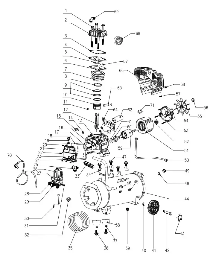
At www.lidl-service.com you can download this and many more manuals, product videos plus installation software. The QR code takes you directly to the Lidl service page (www.lidl-service.com) and you can open your operating manual by entering the article number (IAN) 360588_2010.
CE – Declaration of Conformity
 Translation of the original EC declaration of conformity scheppach Fabrikation von Holzbearbeitungsmaschinen GmbH, Günzburger Str. 69, D-89335 Ichenhausen hereby declares the following conformity under the EU Directive and standards for the following article
Brand : Parkside
Article name: COMPRESSOR – PKO 24 B2
Art.-Bezeichnung: KOMPRESSOR – PKO 24 B2
Art. no.: 3906144974-3906144980; 39061449915-39061449916
Ident. no.: 01001 – 94619
| X | 2014/29/EU | 2004/22/EC | 89/686/EC_96/58/EC | ||
| 2014/35/EU | X | 2014/68/EU | 90/396/EC | ||
| X | 2014/30/EU | X | 2 011/6 5/ E U * |
| X | 2006/42/EC |
| Annex IV Notified Body: Notified Body No.: Certificate No.: |
| X | 2000/14/EC_2005/88/EC |
| Annex V | |
| X | Annex VI Noise: measured LWA = 92.9 dB(A); guaranteed LWA= 97 dB(A) P = KW; L/Ø = cm Notified Body: TÜV SÜD Industrie Service GmbH Westendstrasse 199; 80686 München Notified Body No.: 0036 |
| 2010/26/EC | |
| Emission. No: |
Standard references:
1012-1:2010; EN 60204-1:2018; EN 61000-6-1:2007; EN 61000-6-3:2007/A1:2011; EN 50581:2012;
286-1:1998/A1:2002
This declaration of conformity is issued under the sole responsibility of the manufacturer.
* The object of the declaration described above fulfils the regulations of the directive 2011/65/EU of the European Parliament and Council from 8th June 2011, on
the restriction of the use of certain hazardous substances in electrical and electronic equipment.
Ichenhausen, den 16.02.2021 _____ Unterschrift / Andreas Pecher / Head of Project Management
First CE: 2019
Subject to change without notice
Documents registrar: Thomas Schuster
Günzburger Str. 69, D-89335 Ichenhausen


www.fcsc.org
Paper made from recycled material
FSC®C160731
SCHEPPACH FABRIKATION VON HOLZBEARBEITUNGSMASCHINEN GMBH
Günzburger Str. 69
D-89335 Ichenhausen
Last information update
Update: 02 / 2021 · Ident.-No.: 360588_2010_3906144977
Manual


INVERTER WELDER
Operation and Safety Notes Translation of the original instructions

Before reading, unfold the page containing the illustrations and familiarise yourself with all functions of the device.
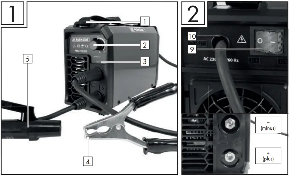
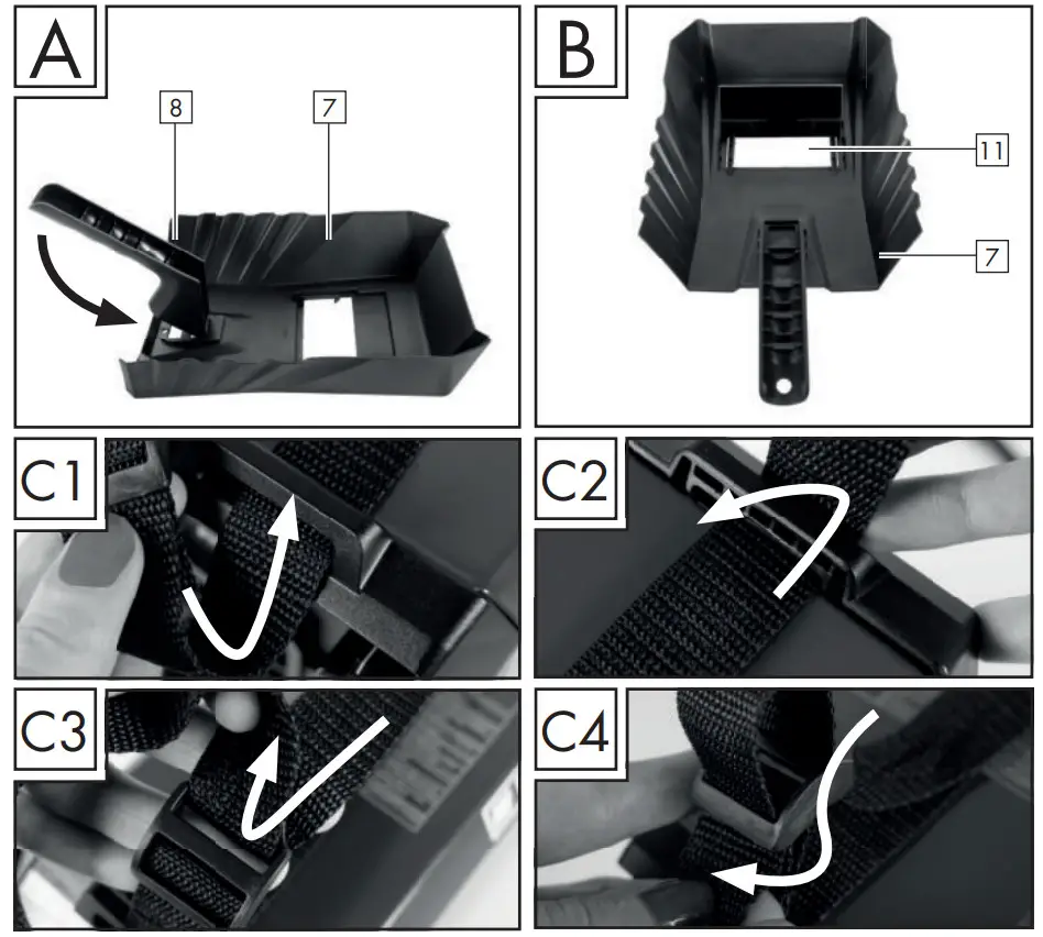
List of pictograms used
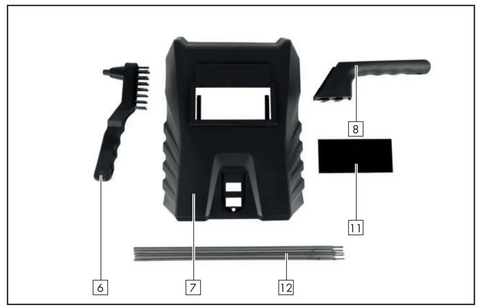 |
Caution! Read the operating instructions! |  |
Risk of serious injury or death. |
 |
Power input; Number of phases and Alternating current symbol and rated value of the frequency. |
Caution! Risk of electric shock! |
|
 |
Important note! | ||
| Do not dispose of electrical devices in household waste! |  |
Dispose of the device and packaging in an environmentally friendly manner. | |
 |
Never use the device in the open or when it’s raining! |  |
Manual arc welding with encased rod electrodes. |
 |
Electric shock from the welding electrode can be fatal! |  |
Protection class. |
 |
Inhalation of welding fumes can endanger your health. |  |
Suitable for welding under increased electrical hazards. |
 |
Welding sparks can cause an explosion or fire. |  |
Single-phase static frequency converter-transformer- commutator. |
 |
Arc beams can damage your eyes and injure your skin. | H | Insulation class. |
 |
Electromagnetic fields can disrupt the function of cardiac pacemakers. |  |
Direct current. |
 |
Warning: Potential hazards! | Made from recycling material. | |
| X % | Duty cycle. | U0 | Rated value of the open-circuit voltage |
| I1 max | Greatest rated value of the mains current | U1 | Rated value of the mains voltage |
| I2 max | Greatest rated value of the welding current | U2 | Standardized operating voltage |
| I1 eff | The effective value of the greatest mains current |
INVERTER WELDER PISA 120 B3
Introduction
 Congratulations!
You have purchased one of our high-quality products. Please familiarise yourself with the product before using it for the first time. Please also read the safety instructions carefully. This product must be set up or used only by people who have been trained to do so.
KEEP OUT OF THE REACH OF CHILDREN!
Intended use
This welding device is ideal for welding metals such as carbon steel, steel alloy, other stainless steel, copper, aluminium, titanium, etc. The product has a control lamp, a heat protection display, and a cooling fan. In addition, it is fitted with a carrying strap so that the product can be lifted and moved safely. If it is not handled properly the product can be dangerous for individuals, animals, and property. Use the product only as described and only for the specific applications as stated. Keep these instructions in a safe place. Ensure you hand over all documentation when passing the product on to anyone else. Any use that differs from the intended use as stated above is prohibited and potentially dangerous. Damage or injury caused by misuse or disregarding the above warning is not covered by the warranty or any liability on the part of the manufacturer. The device is intended for professional use. Commercial use will void the guarantee.
Package contents
| 1 | Inverter welder |
| 1 | Welding mask |
| 2 | Welding cables |
| 1 | Combi wire brush with slag hammer |
| 1 | Carrying strap |
| 5 | Welding electrodes (2 x 1.6 mm; 2 x 2.0 mm; 1 x 2.5 mm) |
| 1 | Operating instructions |
Parts description
| 1. Carrying strap | 7. Welding mask |
| 2. Rotary knob | 8. Handle |
| 3. Control lamp for overheating | 9. ON/OFF switch |
| 4. Ground terminal | 10. Power cable 4 m |
| 5. Electrode holder | 11. Protective glass |
| 6. Combi wire brush with slag hammer | 12. Welding electrodes |
Technical specifications
| Mains connection: | 230 V 50/60 Hz |
| Nominal power input: | 3.6 kW |
| Max. welding current and the appropriate standardized operating voltage: | 10 A/20.4 V – 120 A/24.8 V |
| Rated value of the mains voltage: | U1:230 V |
| Greatest rated value of the mains current: | I1max: 22 A |
| Maximum effective input current: | I1eff: 11 A |
| Rated value of the open-circuit voltage: | U0: 80 V |
| Protection class: | IP21S |
| Weight: | approx. 3 kg |
| Duty cycle X: | 30% at 40 °C and 120 A |
| Falling characteristic | |
| Material thicknesses which can be welded: | 1.5 mm —3.0 mm |
Please read the operating instructions with care and observe the notes described. Familiarise yourself with the device, its proper use, and the safety instructions based on these operating instructions. The rating plate contains all technical data of this welding device; please learn about the technical features of this device.
 Keep the packaging material away from small children. There is a risk of suffocation!
- This device may be used by children aged 16 years and older, and by persons with reduced physical, sensory or mental capacities, or a lack of experience and knowledge if they are supervised or have been instructed in how to use the device safely and understand the dangers that may arise when using it. Do not allow children to play with the device. Cleaning and day-to-day maintenance must not be performed by children without supervision.
- Repairs or/and maintenance work must only be carried out by qualified electricians.
- Only use the weld cable provided in the scope of delivery.
- During operation, the device should not be positioned directly on the wall, covered, or jammed between other devices so that sufficient air can be absorbed through the ventilation slots. Make sure that the device is correctly connected to the supply voltage. Avoid any form of tensile stress of the power cable. Disconnect the plug from the socket prior to setting up the device in another location.
- If the device is not in operation, always switch it off by pressing the ON/OFF switch. Place the electrode holder on an insulated surface and only remove it from the holder after allowing it to cool down for 15 minutes.
- Pay attention to the condition of the welding cable, electrode holder, and earth terminal. The wear and tear of the insulation and the live parts can lead to hazards and reduce the quality of the welding work.
- Arc welding creates sparks, molten metal parts, and smoke. Therefore ensure that: All flammable substances and/or materials are removed from the work station and its immediate surrounding.
- Ensure the workstation is ventilated.
- Do not weld on containers, vessels, or tubes that contain or contained flammable liquids or gases.
- Avoid any form of direct contact with the welding current circuit. The open-circuit voltage between the electrode holder and earth terminal can be dangerous, there is a risk of electric shock.
- Do not store or use the device in a damp or wet environment or in the rain. Protection rating IP21S is applicable in this case.
- Protect your eyes using the appropriate protective glasses (DIN level 9-10), which are fastened to the supplied welding Safety instructions mask. Wear gloves and dry protective clothing that are free of oil and grease to protect the skin from exposure to ultraviolet radiation of the arc.
- Do not use the welding power source to defrost pipes.
Please note:
- The light radiation emitted by the electric arc can damage the eyes and cause burns to the skin.
- Arc welding creates sparks and drops of melted metal. The welded workpiece starts to glow and remains hot for a relatively long period. Therefore, do not touch the workpiece with bare hands.
- Arc welding can cause vapours to be released that may be hazardous to health. Be careful not to inhale these vapours.
- Protect yourself from the harmful effects of the electric arc and keep people that are not involved in the work away from the arc maintaining a distance of at least 2 m.
ATTENTION!
- During the operation of the welding device, other consumers may experience problems with the voltage supply depending on the network conditions at the connection point. In case of doubt, please contact your energy supply company.
- During the operation of the welding device, other devices may malfunction, e.g. hearing aids, cardiac pacemakers, etc.
- Potential hazards during electric arc welding
There are a series of potential hazards that can occur during electric arc welding. It is therefore particularly important for the welder to observe the following rules to avoid endangering him/ herself and others and to prevent damage to people and the device.
- Work on the voltage side, e.g.on cables, plugs, sockets etc., may only be carried out by qualified electricians according to national and local regulations.
- In the event of accidents, disconnect the welding device from the mains voltage immediately.
- If electrical contact voltages occur, switch off the device immediately and have it checked by a qualified electrician.
- Always ensure good electrical contacts on the welding current side.
- Always wear insulating gloves on both hands during welding work. These provide protection from electrical shocks (no-load voltage of the welding current circuit), harmful radiations (heat and UV radiation) and incandescent metal and splashes of slag.
- Wear sturdy, insulating shoes. The shoes should also insulate when exposed to moisture. Loafers are not suitable as falling incandescent metal droplets can cause burns.
- Wear suitable protective clothing, no synthetic garments.
- Do not look into the electric arc without eye protection; only use a welding mask with the prescribed protective glass as per DIN. In addition to light
and heat radiation, which can dazzle or cause burns, the electric arc also emits UV radiation. Without suitable protection, the invisible ultraviolet radiation can cause very painful conjunctivitis which is not apparent until several hours later. Furthermore, UV radiation can cause burns with sunburn-like effects on unprotected parts of the body. - Any persons in the vicinity of the electric arc or helpers must also be informed of the dangers and be equipped with the necessary protective equipment. If necessary, set up protective walls.
- Ensure an adequate supply of fresh air whilst welding, particularly in small spaces, as it produces smoke and harmful gases.
- No welding work may be carried out on containers that have been used for storing gases, fuels, mineral oils or similar – even if they have been empty for a long time – as possible residues may present a risk of explosion.
- Special regulations apply in rooms where there is a risk of fire or explosion.
- Welded joints that are subject to heavy stress loads and are required to comply with certain safety requirements may only be carried out by specially trained and certified welders. Examples of this are pressure vessels, running rails, tow bars, etc.
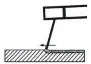 ATTENTION! Always connect the earth terminal as close as possible to the point of weld to provide the shortest possible path for the welding current from the electrode to the earth terminal. Never connect the earth terminal to the housing of the welding device! Never connect the earth terminal to earthed arts far away from the workpiece, e.g. a water pipe in another corner of the room. This could otherwise damage the protective bonding system of
the room you are welding.
- Do not use the welding device in the rain.
- Do not use the welding device in a moist environment.
- Only place the welding device on a level surface.
- The output is rated at an ambient temperature of 20 °C. The welding time can be reduced at higher temperatures.
Risk of electric shock:
![]() Electric shock from the welding electrode can be fatal. Do not weld in rain or snow. Wear dry insulating gloves. Do not touch the electrodes with bare hands. Do not wear wet or damaged gloves. Protect yourself from electric shock with insulation against the workpiece. Do not open the device housing.
Electric shock from the welding electrode can be fatal. Do not weld in rain or snow. Wear dry insulating gloves. Do not touch the electrodes with bare hands. Do not wear wet or damaged gloves. Protect yourself from electric shock with insulation against the workpiece. Do not open the device housing.
Danger from welding fumes:
- Inhalation of welding fumes can endanger health. Do not keep your head in the fumes. Use the equipment in open areas. Use extractors to remove the fumes.
Danger from welding sparks:
- Welding sparks can cause an explosion or fire. Keep flammable substances away from the welding location. Do not weld next to flammable substances. Welding sparks can cause fires. Keep a fire extinguisher close by and an observer should be present to be able to use it immediately. Do not weld on drums or any other closed containers.
Danger from arc beams:
- Arc beams can damage your eyes and injure your skin.
Wear a hat and safety goggles.
Wear hearing protection and high, closed shirt collars.
Wear welding safety helmets and make sure you use the appropriate filter settings. Wear complete body protection.
Danger from electromagnetic fields:
- Welding current generates electromagnetic fields. Do not use if you have a medical implant. Never wrap the welding cable around your body. Guide welding cables together.
Welding mask-specific safety instructions
- With the help of a bright light source (e.g. lighter) examine the proper functioning of the welding mask prior to starting with any welding work.
- Weld spatters can damage the protective screen. Immediately replace damaged or scratched protective screens.
- Immediately replace damaged or highly contaminated or splattered components.
- The device must only be operated by people over the age of 16.
- Please familiarise yourself with the welding safety instructions. Also, refer to the safety instructions of your welding device.
- Always wear a welding mask while welding. If it is not used, you could sustain severe lesions to the retina.
- Always wear protective clothing during welding operations.
- Never use the welding mask without the protective screen.
- Regularly replace the protective screen to ensure good visibility and fatigue-proof work.
An environment with increased electrical hazard
When welding in environments with increased electrical hazards, the following safety instructions must be observed. Environments with increased electrical hazard may be encountered, for example:
- In workplaces where the space for movement is restricted, such that the welder is working in a forced posture (e.g.: kneeling, sitting, lying) and is touching electrically conductive parts;
- In workplaces which are restricted completely or in part in terms of electrical conductivity and where there is a high risk through avoidable or accidental touching by the welder;
- In wet, humid, or hot workplaces where the air humidity or weld significantly reduces the resistance of human skin and the insulating properties or effect of protective equipment.
Even a metal conductor or scaffolding can create an environment with increased electrical hazards.
In this type of environment, insulated mats and pads must be used. Furthermore, gauntlet gloves and head protection made of leather or other insulating materials must be worn to insulate the body against Earth. The welding power source must be located outside the working area or electrically conductive surfaces and out of the welder’s reach.
Additional protection against a shock from the mains’ power in the event a fault can be provided by using a fault-circuit interrupter, which is operated with a leakage current of no more than 30 mA and covers all mains-powered devices in close proximity. The fault-circuit interrupter must be suitable for all types of current.
There must be means of rapid electrical isolation of the welding power source or the welding circuit (e.g. emergency stop device) which are easily accessible.
When using welding devices under electrically dangerous conditions, the output voltage of the welding device must be greater than 113 volts when idling (peak value). Based on the output voltage this welding device may be used in these conditions.
Welding in tight spaces
When welding in tight spaces this may pose a hazard through toxic gases (risk of suffocation). In tight spaces, you may only weld if there are trained individuals in the immediate vicinity who can intervene if necessary. In this case, before starting the welding procedure, an expert must carry out an assessment in order to determine what steps are necessary, in order to guarantee safety at work and which precautionary measures should be taken during the actual welding procedure.
Total of open-circuit voltages
When more than one welding power source is operated at the same time, their open-circuit voltages may add up and lead to an increased electrical hazard. Welding power sources must be connected in such a way that the danger is minimized. The individual welding power sources, with their individual control units and connections must be clearly marked, in order to be able to identify which device belongs to which welding power circuit.
Using shoulder straps
Welding must not take place if the welding power source is being carried e.g. with a shoulder strap. This is intended to prevent:
- The risk of losing your balance if the lines or hoses which are connected are pulled
- The increased risk of an electric shock as the welder comes into contact with the earth if he/she is using a Class I welding power source, the housing of which is earthed through its conductor.
Protective clothing
At work, the welder must protect his/her whole body by using appropriate clothing and face protection against radiation and burns. The following steps must be observed:
- Wear protective clothing prior to welding work
- Wear gloves.
- Open windows or use fans to guarantee air supply.
- Wear safety goggles and a face mask.
- Gauntlet gloves made of a suitable material (leather) must be worn on both hands. They must be in perfect condition.
- A suitable apron must be worn to protect clothing from flying sparks and burns. When specific work, e.g. overhead welding, is required, a protective suit must be worn and, if necessary, even head protection.
Protection against rays and burns
- Warn of the danger to the eyes by hanging up a sign saying “Caution! Do not look into flames!”. The workplaces must be shielded so that the persons in the vicinity are protected. Unauthorised persons must be kept away from welding work.
- The walls in the immediate vicinity of fixed workplaces should neither be bright coloured or shiny. Windows up to head height must be protected to prevent rays from penetrating or reflecting through them, e.g. by using suitable paint.
EMC Device Classification
According to the standard IEC 60974-10, this is a welding device in electromagnetic compatibility Class A. Class A devices are devices that are suitable for use in all other areas except living areas and areas that are directly connected to a low-voltage supply main that (also) supplies residential buildings. Class A devices must adhere to the Class A limit values.
WARNING NOTICE: Class A devices are intended for use in an industrial environment. Due to the power-related as well as the radiated interference variables, difficulties might arise in ensuring electromagnetic compatibility in other environments.
Even if the device complies with the emission limit values in accordance with the standard, such devices can still cause electromagnetic interference insensitive systems and devices. The user is responsible for faults caused by the arc while working, and the user must take suitable protective measures. In doing so, the operator must consider the following:
- network, control, signal and telecommunication lines
- computers and other microprocessor-controlled devices
- TVs, radios and other playback devices
- electronic and electrical safety equipment
- people with cardiac pacemakers or hearing aids
- measurement and calibration devices
- interference immunity of other equipment nearby
- the time of day at which the work is being done. The following is recommended to reduce possible interference radiation:
- equip the mains connection with a mains filter
- service the device regularly and keep it in good condition
- welding cables should be completely uncoiled and run as close to parallel with the floor as possible
- if possible, devices and systems at risk from interference radiation should be removed from the work area or shielded.
The product is intended solely for professional use.
Before use
Take the device and accessories out of the packaging and check them for damage (e.g. transport damage).
- Fix the carrying strap 1 onto the device (see Fig. C1 – C4).
Fit welding mask
- Fit the handle 8 onto the welding mask 7, as shown in Fig. A.
- Fit the protective glass 11 onto the welding mask 7, as shown in Fig. A.
- The protective glass 11 must be pushed in from the top.
Note: If you are not able to push the protective glass 11 in fully, gently press on the outside of the protective glass 11
Using the device
Note: The welding device is designed for welding with electrodes.
- Use the electrode holder clamps without protruding bracket screws, which meet the current safety standards.
- Make sure that the ON/OFF switch 9 is set to position “O” (“OFF”) or that the power cable 10 is not plugged into the socket.
- Connect the welding cable according to its polarity and in accordance with the specifications of the electrode manufacturer.
- To do this, connect the connector of the earth terminal 4 (black) with the relevant output on the inverter welder (black, marked with “-”).
- Connect the connector of the electrode holder 5 (red) with the relevant output on the inverter welder (red, marked with “+”).
- Put on appropriate protective clothing in accordance with the specifications and prepare your workspace.
- Connect the earth terminal 4 to the workpiece.
- Clamp the electrode into the electrode holder 5 .
- Switch the device on by setting the ON/OFF switch to the 9 “I” (“ON”) position.
- Adjust the welding current using the rotary knob 2 depending on the electrode being used.
Note: See the following table for information on the welding current to be used, depending on the electrode diameter.
| Ø Electrode | Welding current |
| 1.6 mm | 40 – 55 A |
| 2.0 mm | 55 – 65 A |
| 2.5 mm | 65 – 80 A |
| 3.2 mm | 80 – 120 A |
 Attention: Do not bring the earth terminal 4 and the electrode holder 5 / electrodes into direct contact with one another.
Attention: When welding with electrodes (MMA – manual metal arc welding – electrode welding), the electrode holder 5 and the earth terminal 4 must be connected in accordance with the specifications of the electrodes to plus (+) or minus (-).
- Hold the welding mask 7 in front of the face and start the welding procedure.
- To stop the procedure, set the ON/ OFF switch 9 to “O” (“OFF”) position.
ATTENTION!
When the thermal sensor is triggered, the yellow control lamp 3 lights up. In this case, it will not be possible to continue welding. The device will remain in operation so that the fan can cool the device. As soon as the device is ready for operation again, the yellow control lamp 3 will switch off automatically. The
The welding function can now be used again.
ATTENTION!
Make sure that you do not rub the electrodes. Doing this can damage the workpiece and make it more difficult to ignite the arc. After the arc is ignited, maintain the correct gap from the workpiece. The distance should be appropriate to the diameter of the electrode used. When welding maintains this gap as accurately and consistently as possible. The angle between the electrode and the direction of operation should be between 20° and 30°.
ATTENTION!
The welding clamp and welding electrodes must be placed on the insulated bracket after welding. Wait until the electrode is cooled before removing the welding slag. To weld an intermittent weld seam again you must first remove the welding slag at the welding position.
ATTENTION!
A voltage that is 10% below the rated input voltage of the welding device can have the following consequences:
- The power to the device will reduce.
- The arc stops or becomes unstable.
ATTENTION!
- The arc radiation can lead to inflammation of the eyes and skin burns.
- Casting and welding slag can cause eye injuries and burns.
- Wear tinted safety goggles or a protective mask.
- The safety mask must meet the EN175 safety standards.
- It is essential that you only use the welding cable which is included with the delivery (10 mm 2 ).
Welding
Choose between push and drag welding. The following section shows the impact of the direction of movement on the properties of the weld seam:
| Push welding | Drag welding | |
 |
 |
|
| Burn | smaller | larger |
| Weld seam width | larger | smaller |
| Weld bead | flatter | higher |
| Weld seam fault | larger | smaller |
Note: You decide for yourself which type of welding is most suitable, once you have welded a sample piece.
Note: Once it has worn down completely, the electrode must be replaced.
Maintenance and cleaning
Note: The welding device must be regularly serviced and overhauled for proper function and for compliance with the safety requirements. Improper and the wrong operation may cause failures and damage to the device.
- Before performing cleaning work on the welding tool, disconnect the power cable 10 from the power outlet to ensure the tool is safely isolated from the power supply.
- Clean the exterior of the welding device and its accessories regularly. Use compressed air, cotton waste or a brush to remove dirt and dust.
Note: The following kinds of maintenance work must be performed only by suitably qualified personnel.
- The current regulator, earthing device, internal cables, the coupling device of the welding torch and adjusting screws must be serviced regularly. Re-tighten loose screws and replace rusty screws (replacement M4 x 10 screws are available in any commercial hardware store).
- Check the insulation resistance levels of the welding device regularly. To do this use an appropriate measuring device.
- In case of a defect or a necessary replacement of equipment parts, please contact the appropriately qualified personnel.
Information about recycling and disposal
![]() Don’t throw away – recycle
Don’t throw away – recycle
Please return this device, accessories and packaging to your local recycling depot.
According to European Directive 2012/19/EU, used electrical devices must be collected separately for environmentally compatible recycling or recovery. Please return this device to an approved waste management company or use your municipal waste collection service. Please ensure you comply with local regulations. If you have any questions, please contact your local authority or waste management company.
EU Declaration of Conformity
We,
C.M.C. GmbH
Responsible for documentation:
Dr Christian Weyler
Katharina-Loth-Str. 15
66386 St. Ingbert
Germany
hereby take sole responsibility for declaring that the product
Inverter welder
Art. no.: 2338
Year of manufacture: 2021/18
IAN: 337360_2007
Model: PISG 120 B3
meets the basic safety requirements as specified in the European Directives
EC low-voltage directive:
2014 / 35 / EU
EC Guideline on Electromagnetic Compatibility:
2014 / 30 / EU
RoHS directive:
2011 / 65 / EU+2015/863/EU
and the amendments to these Directives. The object of the declaration described above meets the requirements of Directive 2011/65/EU of the European Parliament and of the Council of 8 June 2011 on the restriction of the use of certain hazardous substances in electrical and electronic equipment. This conformity assessment is based on the following harmonised standards:
EN 60974-1:2018/A1:2019
EN 60974-10:2014/A1:2015
St. Ingbert, 22/10/2020

pp Dr Christian Weyler
– Quality Assurance –
Warranty and service information
Warranty from Creative Marketing & Consulting GmbH
Dear Customer,
The warranty for this equipment is 3 years from the date of purchase. In the event of product defects, you have legal rights against the retailer of this product. Your statutory rights are not affected in any way by our warranty conditions, which are described below.
Warranty conditions
The warranty period begins on the date of purchase. Please retain the original sales receipt. This document is required as your proof of purchase.
Should this product show any defect in materials or manufacture within 3 years from the date of purchase, we will repair or replace it – at our discretion – free of charge. This warranty service requires that you retain proof of purchase (sales receipt) for the defective device for the three year period and that you briefly explain in writing what the fault entails and when it occurred. If the defect is covered by our warranty, we will repair and return your product or send
you a replacement. The original warranty period is not extended when a device is repaired or replaced.
The warranty period and statutory claims for defects
The warranty period is not extended by the guarantee. This also applies to replaced and repaired parts. Any damages or defects detected at the time of purchase must be reported immediately after unpacking. Any incidental repairs after the warranty period are subject to a fee.
Extent of warranty
This device has been manufactured according to strict quality guidelines and carefully inspected before delivery. The warranty applies to material and manufacturing defects only. This warranty does not extend to product parts, which are subject to normal wear and tear and can thus be regarded as consumable parts, or for damages to fragile parts, e.g. switches, rechargeable batteries or parts made from glass.
This warranty is voided if the product becomes damaged or is improperly used or maintained. For proper use of the product, all of the instructions given in the operating instructions must be followed precisely. If the operating instructions advise you or warn you against certain uses or actions, these must be avoided in all circumstances.
The product is for consumer use only and is not intended for commercial or trade use. The warranty becomes void in the event of misuse and improper use, use of force, and any work on the device that has not been carried out by our authorised service branch.
Processing of warranty claims
To ensure prompt processing of your claim, please follow the instructions given below.
Please retain the proof of purchase and the article number (e.g. IAN) for all inquiries. The product number can be found on the type plate, an engraving, the cover page of your instructions (bottom left), or the sticker on the back or underside of the device.
In the event of malfunctions or other defects, please first contact our service department below by phone or email. If your product is found to be defective,
you can then send your product with proof of purchase (till receipt) and a statement describing what the fault involves and when it occurred free of charge to the service address given.
Note:
You can download this handbook and many more, as well as product videos and software at www.lidl-service.com.
With this QR code, you can gain immediate access to the Lidl Service page (www.lidl-service.com) and you can open your operating instructions by entering the article number (IAN) 337360.

Service
How to contact us:
GB
Name: C. M. C. GmbH
Website: www.cmc-creative.de
E-mail: [email protected]
Phone: 0-808-189-0652
Registered office: Germany
IAN 337360_2007
Please note that the following address is not a service address. Please first contact the service point given above.
Address: C. M. C. GmbH
Katharina-Loth-Str. 15
66386 St. Ingbert
GERMANY
Ordering spare parts:
www.ersatzteile.cmc-creative.de

PASSP 20-Li A2 Cordless Impact Wrench 20V
Instruction Manual
CORDLESS IMPACT WRENCH 20V
Before reading, unfold the page containing the illustrations and familiarise yourself with all functions of the device.
Translation of the original instructions
All Parkside tools and the chargers PLG 20 A1/A4/C1/A2/C2/A3/C3/PDSLG 20 A1 of the X20V Team series are compatible with the PAP 20 A1/A2/A3/B1/B3 battery pack.
| Charging times | 2 Ah Battery pack | 3 Ah Battery pack | 4 Ah Battery pack |
| Charging currents | Akku PAP 20 Al/B1 | Akku AP 20 A2 | Akku PAP 20 A3/B3 |
| Charger PLG 20 Al/A4/C1 , | 60 min | 90 min | 120 min |
| Chargeur | 24A | 24A | 24A |
| Charger PLG 20 A2/C2 Chargeur |
45 min | 60 min | 80 min |
| 3,5 A | 3,5 A | 3,5 A | |
| Charger PLG 20 A3/C3 | 35 min | 45 min | 60 min |
| Ladegerat | 3,8 A | 4,5 A | 4,5 A |
| max. 4,5 A | 35 min | 45 min | 60 min |
| Charger | 3,8 A | 4,5 A | 4,5 A |
CORDLESS IMPACT WRENCH 20V PASSP 20-Li A2
Congratulations on the purchase of your new tool. You have chosen a high-quality product. The operating instructions are part of this product. They contain important information about safety, usage and disposal. Before using the product, please familiarise yourself with all operating and safety instructions. Use the product only as described and for the range of applications specified. Please also pass these operating instructions on to any future owner.
Intended use
This appliance is intended for screwing in and unscrewing screws as well as for tightening and loosening nuts. The appliance has a clockwise/ anticlockwise rotation, a 1/2″ external square drive bit holder and an LED working light. The light on this appliance is intended to illuminate the immediate working area of the appliance. The rotary impact function of the appliance enables the power of the motor to be converted into uniform rotary impacts. The impact mechanism comes into effect during tightening and loosening. The appliance is designed for use by adults. Young people under 16 years of age may only use the appliance under supervision. The manufacturer accepts no liability for damages caused by improper use or incorrect operation of the appliance.
Use this appliance only as described and for the areas of applications specified. The tool is not intended for commercial use. Any other usage or modification of the tool is deemed to be improper and carries a significant risk of accidents. The manufacturer accepts no responsibility for damage attributable to misuse.
Features
- Tool holder
- Rotational direction switch/lock
- Belt clip
- Fixing screw
- LED work light
- Torque display
- Torque selector
- ON/OFF switch/speed control
- Battery pack*
- Release button for the battery pack
- High-speed charger*
- Battery display LED
- Battery charge level button
- Red charge control LED
- Green charge control LED
- Sockets 1/2″ to 3/4″ adapter
Package contents
- 1 cordless impact wrench 20V
- 1 1/2″ to 3/4″ adapter
- 3 sockets (17/19/21 mm)
- 1 belt clip
- 1 carrying case
- 1 set of operating instructions
Technical data
Cordless impact wrench 20V PASSP 20-Li A2
| Rated voltage | 20 V = (DC) |
| Rated idle speed | 1st gear no 0-660 rpm 2nd gear no 0-1250 rpm 3rd gear no 0-1550 rpm |
| Impact frequency | 1st gear no 0-500 rpm 2nd gear no 0-1500 rpm 3rd gear no 0-1900 rpm |
| Torque levels | 1st level 130 Nm 2nd level 400 Nm 3rd level 1356 Nm |
| Max. screw capacity | M33 |
| Max. release torque | 1898 Nm |
| Tool holder | 1/2″ |
| Battery PAP 20 A3* Type | LITHIUM-ION |
| Rated voltage | 20 V = (DC) |
| Cnpnrity | 4 Ah |
| Cells | 10 (80 Wh) |
NOTE
Please note that the maximum performance of the device can only be achieved when using the PAP 20 A3/PAP 20 B3 battery.
High-speed battery charger PLG 20 A3*
INPUT
| Rated voltage | 230–240 V ∼, 50 Hz (AC) |
| Rated power consumption | 120w |
| Fuse (internal) | 3.15 A |
OUTPUT
| Rated voltage | 21.5 V (DC) |
| Rated current | 4.5 A |
| Charging time | approx. 60 min |
| Protection class | II / (double insulation) |
* BATTERY AND CHARGER ARE NOT SUPPLIED
Noise emission value
Noise measurement value determined in accordance with EN 62841. The A-rated noise level of the power tool is typically:
Sound pressure level…………………LPA = 108.1dB (A)
Uncertainty S……………………………… KPA = 3 dB
sound power level…………………………………. LWA = 119.1 dB (A)
Uncertainty……………………………. KWA = 3 dB
Vibration emission value
Total vibration values (vector total of three direct-actions) determined in accordance with EN 62841:
Tightening screws and nuts of maximum permissible size = 8.332 m/s2
Uncertainty ah K = 1.5 m/s2
Wear ear muffs!
NOTE
The vibration emission values and the noise emission values given in these instructions have been measured in accordance with a standardized test procedure and can be used for the comparison of the power tool with another tool.
The specified total vibration values and the noise emission values can also be used to make a provisional load estimate.
WARNING!
Depending on the manner in which the power tool is being used and, in particular, the kind of workpiece being worked, the vibration and noise emission values can deviate from the values given in these instructions during actual use of the power tool.
Try to keep the vibration load as low as possible. Measures to reduce the vibration load are, e.g. wearing gloves and limiting the working time. Wherein all states of operation must be included (e.g. times when the power tool is switched off and times where the power tool is switched on but running without load).
WARNING!
Read all safety warnings, instructions, illustrations and specifications provided with this power tool. Failure to follow all instructions listed below may result in electric shock, fire, and/or serious injury.
Save all warnings and instructions for future reference.
The term “power tool” in the warnings refers to your mains-operated (corded) power tool or battery-operated (cordless) power tool.
1. Work area safety
a) Keep work area clean and well lit. Cluttered or dark areas invite accidents.
b) Do not operate power tools in explosive atmospheres, such as in the presence of flammable liquids, gases or dust. Power tools create sparks that may ignite dust or fumes.
c) Keep children and bystanders away while operating a power tool. Distractions can cause you to lose control.
2. Electrical safety
a) Power tool plugs must match the outlet. Never modify the plug in any way. Do not use any adapter plugs with earthed (grounded) power tools. Unmodified plugs and matching outlets will reduce risk of electric shock.
b) Avoid body contact with earthed or grounded surfaces, such as pipes, radiators, ranges and refrigerators. There is an increased risk of electric shock if your body is earthed or grounded.
c) Do not expose power tools to rain or wet conditions. Water entering a power tool will increase the risk of electric shock.
d) Do not abuse the cord. Never use the cord for carrying, pulling or unplugging the power tool. Keep cord away from heat, oil, sharp edges or moving parts. Damaged or entangled cords increase the risk of electric shock.
e) When operating a power tool outdoors, use an extension cord suitable for outdoor use. The use of a cord suitable for outdoor use reduces the risk of electric shock.
f) If operating a power tool in a damp location is unavoidable, use a residual current device (RCD) protected supply. The use of an RCD reduces the risk of electric shock.
3. Personal safety
a) Stay alert, watch what you are doing, and use common sense when operating a power tool. Do not use a power tool while you are tired or under the influence of drugs, alcohol, or medication. A moment of inattention while operating power tools may result in serious personal injury.
b) Use personal protective equipment. Always wear eye protection. Protective equipment such as a dust mask, non-skid safety shoes, hard hat or hearing protection used for appropriate conditions will reduce personal injuries.
c) Prevent unintentional starting. Ensure the switch is in the off-position before connecting to a power source and/or battery pack, picking up or carrying the tool. Carrying power tools with your finger on the switch or energizing power tools that have the switch on invites accidents.
d) Remove any adjusting key or wrench before turning the power tool on. A wrench or a key left attached to a rotating part of the power tool may result in personal injury.
e) Do not overreach. Keep proper footing and balance at all times. This enables better control of the power tool in unexpected situations.
f) Dress properly. Do not wear loose clothing or jewelry. Keep your hair and clothing away from moving parts. Loose clothes, jewelry or long hair can be caught in moving parts.
g) If devices are provided for the connection of dust extraction and collection facilities, ensure these are connected and properly used. The use of dust collection can reduce dust-related hazards.
h) Do not allow yourself to get lulled into a false sense of security and do not ignore the safety rules for power tools, even if you are familiar with the power tool after repeated use. A careless action can cause severe injury within a fraction of a second.
4. Power tool use and care
a) Do not force the power tool. Use the correct power tool for your application. The correct power tool will do the job better and safer at the rate for which it was designed.
b) Do not use the power tool if the switch does not turn it on and off. Any power tool that cannot be controlled with the switch is dangerous and must be repaired.
c) Disconnect the plug from the power source and/or remove the battery pack, if detachable, from the power tool before making any adjustments, changing accessories, or storing power tools. Such preventive safety measures reduce the risk of starting the power tool accidentally.
d) Store idle power tools out of the reach of children and do not allow persons unfamiliar with the power tool or these instructions to operate the power tool. Power tools are dangerous in the hands of untrained users.
e) Maintain power tools and accessories. Check for misalignment or binding of moving parts, breakage of parts, and any other condition that may affect the power tool’s operation. If damaged, have the power tool repaired before use. Many accidents are caused by poorly maintained power tools.
f) Keep cutting tools sharp and clean. Properly maintained cutting tools with sharp cutting edges are less likely to bind and are easier to control.
g) Use the power tool, accessories and accessory tools, etc. in accordance with these instructions, taking into account the working conditions and the work to be performed. Use of the power tool for operations different from those intended could result in a hazardous situation.
h) Keep handles and grasping surfaces dry, clean, and free from oil and grease. Slippery handles and grasping surfaces do not allow for safe handling and control of the tool in unexpected situations.
5. Use and handling of the cordless electrical power tool
a) Charge a rechargeable battery using only the charger recommended by the manufacturer. Chargers are often designed for a particular type of rechargeable battery unit. There is a danger of fire if other types of rechargeable battery units are used.
b) Only the rechargeable battery units supplied are to be used with an electrical power tool. The use of other rechargeable battery units may lead to the danger of injury or fire.
c) When they are not being used, store rechargeable battery units away from paperclips, coins, keys, nails, screws or other small metal objects that could cause the contacts to be bridged. Short-circuiting the contacts of a rechargeable battery unit may result in heat damage or fire.
d) Fluids may leak out of rechargeable battery units if they are misused. If this happens, avoid contact with the fluid. If contact occurs, flush the affected area with water. Seek additional medical help if any of the fluid gets into your eyes. Escaping battery fluid may cause skin irritation or burns.
e) Do not use a damaged or modified battery. Damaged or modified batteries may behave unexpectedly and cause fires, explosions or pose a risk of injury.
f) Do not expose a battery to fire or excessively high temperatures. Fire or temperatures in excess of 130°C (265°F) can cause an explosion.
g) Follow all instructions regarding charging and never charge the battery or the cordless tool outside of the temperature range given in the operating instructions. Incorrect charging or charging outside of the permissible temperature range can destroy the battery and increase the risk of fire.
CAUTION! RISK OF EXPLOSION!
Never charge non-rechargeable batteries!
![]() Protect the rechargeable battery from heat, for example from continuous exposure to sunlight, fire, water, and moisture. There is a risk of explosion.
Protect the rechargeable battery from heat, for example from continuous exposure to sunlight, fire, water, and moisture. There is a risk of explosion.
6. Service
a) Have your power tool serviced by a qualified repair person using only identical replacement parts. This will ensure that the safety of the power tool is maintained.
b) Never try to repair damaged batteries. Maintenance of batteries should only be carried out by the manufacturer or an approved customer service centre.
Appliance-specific safety instructions for impact wrenches
- Wear ear muffs when impact screwing. Exposure to loud noise can lead to hearing loss.
- Secure the workpiece. A workpiece securely held by a clamping device or vice is much safer than one held in your hand.
- Hold the power tool firmly. High torques can occur for brief periods while tightening and loosening screws.
- Wait until the power tool has come to a standstill before putting it down. The tool could catch in something and thus lead to loss of control of the power tool.
- Hold the power tool by the insulated gripping surfaces when performing an operation where a screw may hit hidden power lines.
- If a screw comes into contact with a live wire, this may make exposed metal parts of the power tool live and could give the operator an electric shock.
Original accessories/auxiliary equipment
Use only the accessories and additional equipment that are specified in the operating instructions and are compatible with the appliance.
WARNING!
Do not use any accessories that are not recommended by PARKSIDE. Doing so could lead to an electric shock and/or fire.
ATTENTION! Hot surface. There is a risk of burns.
Safety guidelines for battery chargers
- This tool may be used by children aged 8 years and above and by persons with limited physical, sensory, or mental capabilities or lack of experience and knowledge, provided that they are under supervision or have been told how to use the tool safely and are aware of the potential risks. Do not allow children to use the tool as a toy.
- Cleaning and user maintenance tasks may not be carried out by children unless they are supervised.
- To avoid potential risks, if the appliance power cable is damaged, it must be replaced by the manufacturer, its customer service or by a qualified technician.
- The charger is suitable for indoor use only.
WARNING!
To avoid potential risks, if the appliance power cable is damaged, it must be replaced by the manufacturer, its customer service or by a qualified technician.
ATTENTION!
- This charger can only charge the following batteries: PAP 20 A1/PAP 20 A2/ PAP 20 A3/PAP 20 B1/PAP 20 B3.
- A current list of battery compatibility can be found at www.Lidl.de/Akku.
Before use
Charging the battery pack (see fig. A)
CAUTION! Always unplug the appliance before you remove the battery pack or connect the battery pack to the charger.
NOTE
- Never charge the battery pack at an ambient temperature of below 10°C or above 40°C. If a lithium-ion battery is going to be stored for an extended period, the charge level should be checked regularly. The optimum charge level is between 50% and 80%. The storage climate should be cool and dry and the ambient temperature should be between 0°C and 50°C.
- Connect the battery pack to the high-speed battery charger (see fig. A).
- Insert the mains plug into the mains power socket. The green charge control LED lights up briefly, then the red charge control LED lights up.
- The green control LED indicates that the charging process is complete and the battery pack is ready for use.
ATTENTION!
- If the red control LED that the battery pack cannot be charged. flashes, this means has overheated and
- If the red and green control LEDs both flash, this means that the battery pack is defective.
- Push the battery pack into the appliance.
- Switch off the charger for at least 15 minutes between successive charging sessions.
- Also, disconnect the power plug from the mains power socket.
Inserting/removing the battery pack
Attaching the battery pack Pushes the rotation direction switch into the middle position (lock). Push the battery pack into the handle until it clicks into place.
Removing the battery pack
Press the release button and remove the battery pack .
Checking the battery charge level
Press the battery charge level button to check the status of the battery (see also main diagram). The status/remaining charge will be shown on the battery display LED as follows: RED/ORANGE/GREEN = maximum charge RED/ORANGE = medium charge RED = low charge charge the battery
Fitting the belt clip
- Loosen the fixing screw 3a using a standard Phillips screwdriver (not supplied).
- Hold the corresponding hole of the belt clip over that of the screw thread.
- Tighten the fixing screw 3a.
Switching on/off
Turn on
- Press and hold the ON/OFF switch to start up the tool.
- The LED work light lights up when the ON/OFF switch is pressed lightly or fully.
- This provides illumination of the work area in poor lighting conditions.
Switching off
Release the ON/OFF switch the appliance
Setting/preselecting the rotation speed/tightening torque
- Press the torque selector to select the required torque in stages. The selected torque is shown on the torque display.
- Press the ON/OFF switch lightly for a low speed and a low tightening torque. Increasing the pressure increases the speed and the tightening torque.
- The tightening torque depends on the selected speed/torque selection and impact duration.
NOTE
When tightening wheel nuts, however, the smallest torque setting must be selected to avoid over-tightening. The integrated motor brake ensures that the tool stops quickly.
ATTENTION!
The tightening torque actually attained must always be checked with a torque wrench!
Changing the direction of rotation
Change the direction of rotation by pressing the rotation direction switch towards the left or right.
Fitting a socket
Push one of the supplied sockets or the adapter onto the tool holder.
Maintenance and cleaning
WARNING! RISK OF INJURY! Always switch the appliance off and remove the battery before carrying out any work on the appliance.
The tool is maintenance-free.
The appliance must always be kept clean, dry, and free from oil or grease.
Never allow liquids to get into the tool.
Use a dry cloth to clean the housing. Never use petrol, solvents or cleaners which can damage the plastic.
If a lithium-ion battery is going to be stored for an extended period, the charge level should be checked regularly. The optimum charge level is between 50% and 80%. The optimum storage environment is cool and dry.
NOTE
Unlisted replacement parts (such as switches) can be ordered via our service hotline.
Kompernass Handels GmbH warranty
Dear customer,
This appliance comes with a 5-year warranty valid from the date of purchase. In the event that this product has any defects, you, the buyer, have certain statutory rights. Your statutory rights are not limited in any way by the warranty described below.
Warranty conditions
The warranty period starts on the date of purchase. Please keep your receipt in a safe place. This will be required as proof of purchase.
If any material or manufacturing fault occurs within 5 years of the product’s date of purchase, we will either repair or replace the product for you or refund the purchase price (at our discretion). This warranty service requires that you present the defective appliance and the proof of purchase (receipt) within the 5-year warranty period, together with a brief written description of the fault and of when it occurred.
If the defect is covered by the warranty, your product will either be repaired or replaced by us. The repair or replacement of a product does not signify the beginning of a new warranty period.
The X 20 V Team Series battery pack comes with a 3-year warranty valid from the date of purchase.
The warranty period and statutory claims for defects|
The warranty period is not prolonged by repairs effected under the warranty. This also applies to replaced and repaired components. Any damage and defects present at the time of purchase must be reported immediately after unpacking. Repairs carried out after expiry of the warranty period shall be subject to a fee.
Scope of the Warranty
This appliance has been manufactured in accordance with strict quality guidelines and inspected meticulously prior to delivery.
The warranty covers material faults or production faults. The warranty does not extend to product parts subject to normal wear and tear or to fragile parts which could be considered as consumable parts such as switches or parts made of glass.
The warranty does not apply if the product has been damaged, improperly used or improperly maintained. The directions in the operating instructions for the product regarding the proper use of the product are to be strictly followed. Uses and actions that are discouraged in the operating instructions or which are warned against must be avoided.
This product is intended solely for private use and not for commercial purposes. The warranty shall be deemed void in cases of misuse or improper handling, use of force and modifications/repairs which have not been carried out by one of our authorized service centres.
The warranty period does not apply to
- Normal reduction of the battery capacity over time
- Commercial use of the product
- Damage to or alteration of the product by the customer
- Non-compliance with safety and maintenance instructions, operating errors
- Damage caused by natural hazards
Warranty claim procedure
To ensure quick processing of your case, please observe the following instructions:
- Please have the till receipt and the item number (IAN) 364892_2101 available as proof of purchase.
- You will find the item number on the type plate on the product, an engraving on the product, on the front page of the operating instructions (below left) or on the sticker on the rear or bottom of the product.
- If functional or other defects occur, please contact the service department listed either by telephone or by e-mail.
- You can return a defective product to us free of charge to the service address that will be provided to you.
- Ensure that you enclose the proof of purchase (till receipt) and information about what the defect is and when it occurred.
- You can download these instructions along with many other manuals, product videos and installation software at www.lidl-service.com.
This QR code will take you directly to the Lidl service page (www.lidl-service.com) where you can open your operating instructions by entering the item number (IAN) 364892_2101.
WARNING!
- Have your tools repaired by the Service Centre or a qualified electrician and only use genuine replacement parts. This will ensure that the safety of the appliance is maintained.
- Ensure that the power plug or the mains cable is replaced only by the manufacturer of the tool or by an approved customer service provider. This will ensure that the safety of the appliance is maintained.
Service
Service Great Britain
Tel.: 0800 404 7657
E-Mail: [email protected]
Service Ireland
Tel.: 1890 930 034 (0,08 EUR/Min., (peak)) (0,06 EUR/Min., (off peak))
E-Mail: [email protected]
IAN 364892_2101
Importer
Please note that the following address is not the service address. Please use the service address provided in the operating instructions.
KOMPERNASS HANDELS GMBH
BURGSTRASSE 21 44867
BOCHUM GERMANY
www.kompernass.com
Disposal
The packaging is made from environmentally friendly material and can be disposed of at your local recycling plant.
Do not dispose of power tools in your normal domestic waste!
European Directive 2012/19/EU requires that worn-out power tools be collected separately and recycled in an environmentally compatible manner.
Do not dispose of batteries in your normal household waste!
Remove the batteries from the appliance before disposal. Defective or worn-out rechargeable batteries must be recycled according to Directive 2006/66/EC. Take the battery pack and/or appliance to a nearby collection facility.
Please consult your local authorities regarding the suitable disposal of worn out power tools/battery packs.
![]() Dispose of the packaging in an environmentally friendly manner. Note the labelling on the packaging and separate the packaging material components for disposal if necessary. The packaging material is labeled with abbreviations (a) and numbers (b) with the following meanings: 17: plastics, 2022: paper and cardboard, 8098: composites.
Dispose of the packaging in an environmentally friendly manner. Note the labelling on the packaging and separate the packaging material components for disposal if necessary. The packaging material is labeled with abbreviations (a) and numbers (b) with the following meanings: 17: plastics, 2022: paper and cardboard, 8098: composites.
![]() Your local community or municipal authorities can provide information on how to dispose of the worn-out product.
Your local community or municipal authorities can provide information on how to dispose of the worn-out product.
 The product is recyclable, subject to extended producer responsibility and is collected separately.
Translation of the original Conformity Declaration
We, KOMPERNASS HANDELS GMBH, document officer: Mr Semi Uguzlu, BURGSTR. 21, 44867 BOCHUM, GERMANY, hereby declare that this product complies with the following standards, normative documents, and EC directives:
Machinery Directive
(2006/42/EC) EMC
(Electromagnetic Compatibility)
(2014/30/EU)
RoHS Directive
(2011/65/EU)* *
The manufacturer bears full responsibility for compliance with this conformity declaration. The object of the declaration described above complies with the requirements of the Directive 2011/65/EU of the European Parliament and Council of 8 June 2011 on the limitations of use of certain dangerous substances in electrical and electronic appliances. Applied harmonised standards
EN 62841-1:2015
EN 62841-2-2:2014
EN 55014-1:2017/A11:2020
EN 55014-2:2015
EN IEC 63000:2018
Type/appliance designation:
Cordless impact wrench 20V PASSP 20-Li A2
Year of manufacture: 062021
Serial number: IAN 364892_2101
Bochum, 02.06.2021
Semi Uguzlu
– Quality Manager
We reserve the right to make technical changes in the context of further product development.
Ordering a replacement battery
If you want to order a replacement battery for your tool, you can do so easily via the Internet on www.kompernass.com or by telephone. Due to limited stocks, this item may sell out in a relatively short time. NOTE Online ordering of replacement parts is not possible in all countries. In this case, please contact the Service hotline.
Telephone ordering
Service Great Britain
Tel.: 0800 404 7657
Service Ireland
Tel.: 1890 930 034
(0,08 EUR/Min., peak
· 0,06 EUR/Min., off-peak)
To ensure fast processing of your order, have the article number of your appliance to hand (e.g. IAN 364892_2101) in case of questions. The article number can be found on the type plate or the title page of these instructions.

PARKSIDE MPKZ 2000 A1 Multifunction Sliding Cross Cut Mitre Saw

Before reading, unfold the page containing the illustrations and familiarise yourself with all functions of the device.
Explanation of the symbols on the equipment
Introduction
Manufacturer: scheppach
Fabrikation von Holzbearbeitungsmaschinen GmbH Günzburger Straße 69
D-89335 Ichenhausen
Dear customer,
We hope your new tool brings you much enjoyment and success.
Note:
According to the applicable product liability laws, the manufacturer of the device does not assume liability for damages to the product or damages caused by the product that occurs due to:
- Improper handling,
- Non-compliance of the operating instructions,
- Repairs by third parties, not by authorized service technicians,
- Installation and replacement of non-original spare parts,
- Application other than specified,
- A breakdown of the electrical system that occurs due to the non-compliance of the electric regulations and VDE regulations 0100, DIN 57113 / VDE0113.
Please consider:
Read through the complete text in the operating instructions before installing and commissioning the device.
The operating instructions are intended to help the user to become familiar with the machine and take advantage of its application possibilities in accordance with the recommendations.
The operating instructions contain important information
on how to operate the machine safely, professionally and economically, how to avoid danger, costly repairs, reduce downtimes and how to increase the reliability and service life of the machine.
In addition to the safety regulations in the operating instructions, you have to meet the applicable regulations that apply for the operation of the machine in your country.
Keep the operating instructions package with the machine at all times and store it in a plastic cover to protect it from dirt and moisture. Read the instruction manual each time before operating the machine and carefully follow its information. The machine can only be operated by persons who were instructed concerning the operation of the machine and who are informed about the associated dangers. The minimum age requirement must be complied with.
In addition to the safety instructions contained in this operat-ing manual and the specific regulations of your country,
the technical rules generally accepted for the operation of machines of the same type must be observed.
We accept no liability for damage or accidents which arise due to the non-observance of these instructions and the safety information.
Device description
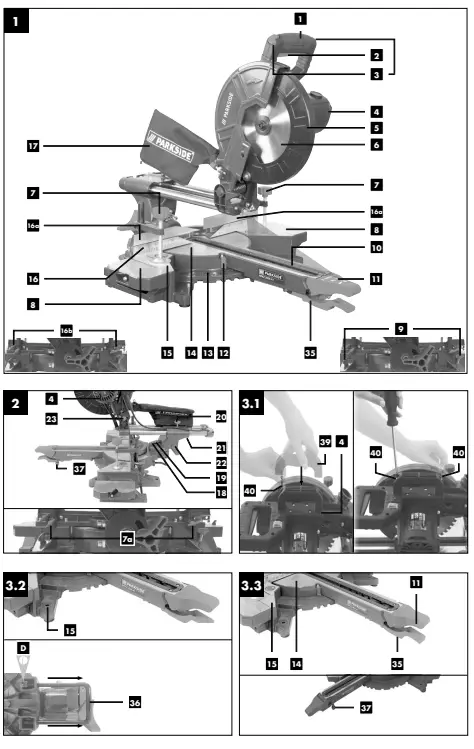
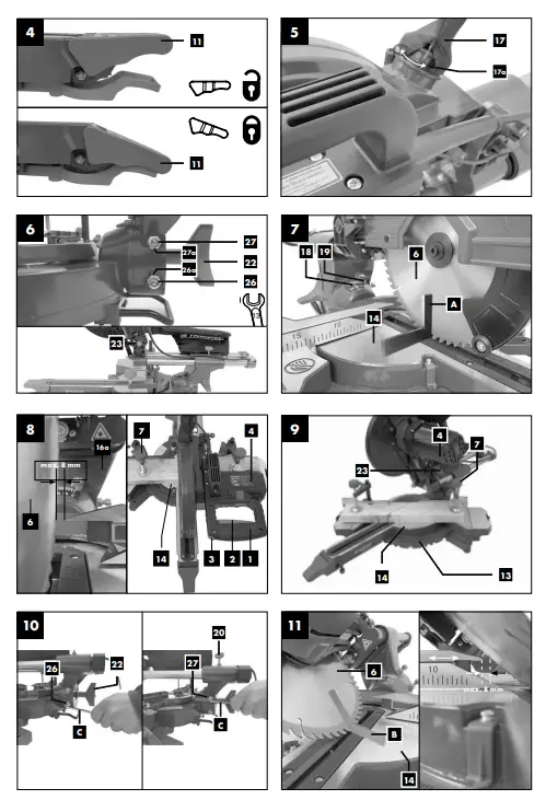
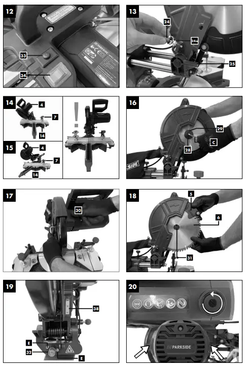
- Handle
- ON/OFF switch
- Lock switch
- Machine head
- Moving saw blade guard
- Saw blade
- Clamping device
- Wing screw
- Workpiece support
- Set screw for workpiece support
- Table insert
- Locking handle
- Pointer (mitre adjustment)
- Scale (mitre adjustment)
- Rotary table
- Fixed saw table
- Stop rail
- Movable stop rail
- Set screw
- Chip collection bag
- Extraction port
- Scale (tilt adjustment)
- Pointer (tilt adjustment)
- Set screw for drag guide
- Drag guide
- Set screw
- Locking bolt
- Screw for cutting depth limiting
- Stop for cutting depth limiting
- Adjusting screw (90°)
- Adjusting screw (45°)
- Flange screw
- Outer flange
- Saw shaft lock
- Inner flange
- Laser
- ON/OFF switch laser
- Speed regulation switch
- Latched position lever
- Tilt protection
- Adjusting screw
- LED working light
- Transport handle
- Phillips screw 5.0 x 25 mm
- A.) 90° stop angle (not supplied)
- B.) 45° stop angle (not supplied)
- C.) Allen key, 6 mm
- D.) Allen key, 3 mm
- E.) Philips screw (laser)
Scope of delivery
- Multifunction sliding cross cut mitre saw
- Transport handle
- 2 x Phillips screw (5.0 x 25 mm)
- 2 x Clamping device (7) (preassembled)
- 2 x Workpiece support (8) (preassembled)
- Chip collection bag (17)
- Allen key 6 mm (C)
- Allen key 3 mm (D)
- Operating manual
Intended use
The multifunction sliding cross cut mitre saw is designed to crosscut wood, plastic, aluminium, copper and metal (not exceeding 15 HRC), respective of the machine’s size. The sliding crosscut mitre saw is not designed for cutting firewood.
Warning! Do not use the sliding cross cut mitre saw to cut materials other than those specified described in manual.
Warning! The supplied saw blade is intended exclusively for sawing the following materials:
wood, wood derived products (MDF, chipboard, plywood, blockboard, hardboard, etc.), wood with nails, plastic, non-ferrous metals and 3 mm mild steel plates.
Note: Wood containing non-galvanised nails or screws can also be safely cut when carefully handled.
Note: Do not use the saw blade to cut galvanised materi-als or wood containing galvanised nails. Do not use the saw blade to saw firewood!
The equipment is to be used only for its prescribed purpose. Any other use is deemed to be a case of misuse. The user / operator and not the manufacturer will be liable for any damage or injuries of any kind caused as a result of this.
The equipment is to be operated only with suitable saw blades. It is prohibited to use any type of cutting-off wheel.
To use the equipment properly you must also observe the safety information, the assembly instructions and the operating instructions to be found in this manual.
All persons who use and service the equipment have to be acquainted with this manual and must be informed about the equipment’s potential hazards. It is also imperative to observe the accident prevention regulations in force in your area. The same applies for the general rules of health and safety at work. The manufacturer will not be liable for any changes made to the equipment nor for any damage resulting from such changes. Even when the equipment is used as prescribed it is still impossible• Contact with the saw blade in the uncovered saw zone.
- Reaching into the running saw blade (cut injuries).
- Kick-back of workpieces and parts of workpieces.
- Saw blade fracturing.
- Catapulting of faulty carbide tips from the saw blade.
- Damage to hearing if ear-muffs are not used as necessary.
- Harmful emissions of wood dust when used in closed rooms. to eliminate certain residual risk factors. The following hazards may arise in connection with the machine’s construction and design:
Please note that our equipment has not been designed for use in commercial, trade or industrial applications. Our warranty will be voided if the equipment is used in commercial, trade or industrial businesses or for equivalent purposes.
Safety information
General power tool safety warnings
WARNING! Read all safety warnings, instructions, illustrations and specifications provided with this power tool. Failure to follow all instructions listed below may result in electric shock, fire and/or serious injury.
Save all warnings and instructions for future reference.
The term “power tool” in the warnings refers to your mains-operated (corded) power tool or battery-operated (cordless) power tool.
Work area safety
- a) Keep work area clean and well lit. Cluttered or dark areas invite accidents.
- b) Do not operate power tools in explosive atmos-pheres, such as in the presence of flammable liquids, gases or dust. Power tools create sparks which may ignite the dust or fumes.
- c) Keep children and bystanders away while op-erating a power tool. Distractions can cause you to lose control.
Electrical safety
- a) Power tool plugs must match the outlet. Never modify the plug in any way. Do not use any adapter plugs with earthed (grounded) power tools. Unmodified plugs and matching outlets will reduce risk of electric shock.
- b) Avoid body contact with earthed or grounded surfaces, such as pipes, radiators, ranges and refrigerators. There is an increased risk of electric shock if your body is earthed or grounded.
- c) Do not expose power tools to rain or wet condi-tions. Water entering a power tool will increase the risk of electric shock.
- d) Do not abuse the cord. Never use the cord for carrying, pulling or unplugging the power tool. Keep cord away from heat, oil, sharp edges or moving parts. Damaged or entangled cords increase the risk of electric shock.
- e) When operating a power tool outdoors, use an extension cord suitable for outdoor use. Use of a cord suitable for outdoor use reduces the risk of electric shock.
- f) If operating a power tool in a damp location is unavoidable, use a residual current device (RCD) protected supply. Use of an RCD reduces the risk of electric shock.
Personal safety
- a) Stay alert, watch what you are doing and use common sense when operating a power tool. Do not use a power tool while you are tired or under the influence of drugs, alcohol or medica-tion. A moment of inattention while operating power tools may result in serious personal injury.
- b) Use personal protective equipment. Always wear eye protection. Protective equipment such as a dust mask, non-skid safety shoes, hard hat or hearing protection used for appropriate conditions will reduce per-sonal injuries.
- c) Prevent unintentional starting. Ensure the switch is in the off-position before connecting to power source and/or battery pack, picking up or carrying the tool. Carrying power tools with your finger on the switch or energising power tools that have the switch on invites accidents.
- d) Remove any adjusting key or wrench before turning the power tool on. A wrench or a key left attached to a rotating part of the power tool may result in personal injury.
- e) Do not overreach. Keep proper footing and balance at all times. This enables better control of the power tool in unexpected situations.
- f) Dress properly. Do not wear loose clothing or jewellery. Keep your hair and clothing away from moving parts. Loose clothes, jewellery or long hair can be caught in moving parts.
- g) If devices are provided for the connection of dust extraction and collection facilities, ensure these are connected and properly used. Use of dust collection can reduce dust-related hazards.
- h) Do not let familiarity gained from frequent use of tools allow you to become complacent and ignore tool safety principles. A careless action can cause severe injury within a fraction of a second.
Power tool use and care
- a) Do not force the power tool. Use the correct power tool for your application. The correct power tool will do the job better and safer at the rate for which it was designed.
- b) Do not use the power tool if the switch does not turn it on and off. Any power tool that cannot be con-trolled with the switch is dangerous and must be repaired.
- c) Disconnect the plug from the power source and/or remove the battery pack, if detachable, from the power tool before making any adjust-ments, changing accessories, or storing power tools. Such preventive safety measures reduce the risk of starting the power tool accidentally.
- d) Store idle power tools out of the reach of chil-dren and do not allow persons unfamiliar with the power tool or these instructions to oper-ate the power tool. Power tools are dangerous in the hands of untrained users.
- e) Maintain power tools and accessories. Check for misalignment or binding of moving parts, breakage of parts and any other condition that may affect the power tool’s operation. If dam-aged, have the power tool repaired before use. Many accidents are caused by poorly maintained power tools.
- f) Keep cutting tools sharp and clean. Properly main-tained cutting tools with sharp cutting edges are less likely to bind and are easier to control.
- g) Use the power tool, accessories and tool bits etc. in accordance with these instructions, tak-ing into account the working conditions and the work to be performed. Use of the power tool for operations different from those intended could result in a hazardous situation.
- h) Keep handles and grasping surfaces dry, clean and free from oil and grease. Slippery handles and grasping surfaces do not allow for safe handling and con-trol of the tool in unexpected situations.
Service
- a) Have your power tool serviced by a qualified repair person using only identical replacement parts. This will ensure that the safety of the power tool is maintained.
Safety instructions for mitre saws
- a) Mitre saws are intended to cut wood or wood-like products and cold metal when they are set at different running speed. Abrasive dust causes moving parts such as the lower guard to jam. Sparks from abrasive cutting will burn the lower guard, the kerf insert and other plastic parts.
- b) Use clamps to support the workpiece when-ever possible. If supporting the workpiece by hand, you must always keep your hand at least 100 mm from either side of the saw blade. Do not use this saw to cut pieces that are too small to be securely clamped or held by hand. If your hand is placed too close to the saw blade, there is an in-creased risk of injury from blade contact.
- c) The workpiece must be stationary and clamped or held against both the fence and the table. Do not feed the workpiece into the blade or cut “freehand” in any way. Unrestrained or moving workpieces could be thrown at high speeds, causing injury.
- d) Push the saw through the workpiece. Do not pull the saw through the workpiece. To make a cut, raise the saw head and pull it out over the workpiece without cutting, start the motor, press the saw head down and push the saw through the workpiece. Cutting on the pull stroke is likely to cause the saw blade to climb on top of the work-piece and violently throw the blade assembly towards the operator.
- e) Never cross your hand over the intended line of cutting either in front or behind the saw blade. Supporting the workpiece “cross handed” i.e. holding the workpiece to the right of the saw blade with your left hand or vice versa is very dangerous.
- f) Do not reach behind the fence with either hand closer than 100 mm from either side of the saw blade, to remove wood scraps, or for any other reason while the blade is spinning. The proximity of the spinning saw blade to your hand may not be obvi-ous and you may be seriously injured.
- g) Inspect your workpiece before cutting. If the workpiece is bowed or warped, clamp it with the outside bowed face toward the fence. Al-ways make certain that there is no gap be-tween the workpiece, fence and table along the line of the cut. Bent or warped workpieces can twist or shift and may cause binding on the spinning saw blade while cutting. There should be no nails or foreign objects in the workpiece.
- h) Do not use the saw until the table is clear of all tools, wood scraps, etc., except for the work-piece. Small debris or loose pieces of wood or other ob-jects that contact the revolving blade can be thrown with high speed.
- i) Cut only one workpiece at a time. Stacked multiple workpieces cannot be adequately clamped or braced and may bind on the blade or shift during cutting.
- j) Ensure the mitre saw is mounted or placed on a level, firm work surface before use. A level and firm work surface reduces the risk of the mitre saw becom-ing unstable.
- k) Plan your work. Every time you change the bevel or mitre angle setting, make sure the adjustable fence is set correctly to support the workpiece and will not interfere with the blade or the guarding system. Without turning the tool “ON” and with no workpiece on the table, move the saw blade through a complete simulated cut to assure there will be no interference or danger of cutting the fence.
- l) Provide adequate support such as table exten-sions, saw horses, etc. for a workpiece that is wider or longer than the table top. Workpieces longer or wider than the mitre saw table can tip if not se-curely supported. If the cut-off piece or workpiece tips, it can lift the lower guard or be thrown by the spinning blade.
- m) Do not use another person as a substitute for a table extension or as additional support. Unsta-ble support for the workpiece can cause the blade to bind or the workpiece to shift during the cutting operation pull-ing you and the helper into the spinning blade.
- n) The cut-off piece must not be jammed or pressed by any means against the spinning saw blade. If confined, i.e. using length stops, the cut-off piece could get wedged against the blade and thrown violently.
- o) Always use a clamp or a fixture designed to properly support round material such as rods or tubing. Rods have a tendency to roll while being cut, causing the blade to “bite” and pull the work with your hand into the blade.
- p) Let the blade reach full speed before contact-ing the workpiece. This will reduce the risk of the work-piece being thrown.
- q) If the workpiece or blade becomes jammed, turn the mitre saw off. Wait for all moving parts to stop and disconnect the plug from the power source and/or remove the battery pack. Then work to free the jammed material. Continued sawing with a jammed workpiece could cause loss of con-trol or damage to the mitre saw.
- r) After finishing the cut, release the switch, hold the saw head down and wait for the blade to stop before removing the cut-off piece. Reaching with your hand near the coasting blade is dangerous.
- s) Hold the handle firmly when making an incom-plete cut or when releasing the switch before the saw head is completely in the down posi-tion. The braking action of the saw may cause the saw head to be suddenly pulled downward, causing a risk of injury. (only applies to saws with braking systems)
Safety Instructions for the handling of saw blades
- Do not use damaged or deformed saw blades.
- Do not use any insertion tools with cracks. Sort out cracked insertion tools. Repairs are not permitted.
- Do not use saw blades made of high speed steel.
- Check the condition of the saw blades before using the multifunction sliding cross cut mitre saw.
- Make sure that a suitable saw blade for the material to be cut is selected.
- Only use saw blades recommended by the manufacturer. Saw blades designed to cut wood and similar materials must comply with EN 847-1.
- Do not use saw blades made of high-speed alloy steel (HSS steel).
- Only use saw blades for which the maximum permissible speed is not lower than the maximum spindle speed of the multifunction sliding cross cut mitre saw and which are suitable for the material to be cut.
- Observe the saw blade direction of rotation.
- Only insertion the saw blade if you have mastered their use.
- Observe the maximum speed. The maximum speed specified on the insertion tool may not be exceeded. If specified, observe the speed range.
- Clean grease, oil and water off of the clamping surfaces.
- Do not use any loose reducing rings or bushes for the reducing of holes on saw blades.
- Make sure that fixed reducer rings for securing the insertion tool have the same diameter and have at least 1/3 of the cutting diameter.
- Make sure that fixed reducer rings are parallel to each other.
- Handle insertion tool with caution. They are ideally stored in the originally package or special containers. Wear protective gloves in order to improve grip and to further reduce the risk of injury.
- Prior to the use of insertion tools, make sure that all protective devices are properly fastened.
- Prior to use, make sure that the insertion tool meets the technical requirements of this electric tool and is properly fastened.
- Only use the supplied saw blade for cutting wood, never for the processing of metals.
- Only use saw blade diameters in accordance with the markings on the saw.
- Use additional workpiece supports, if required for work- piece stability.
- Workpiece support extensions must always be secured and used during work.
- Replace table inserts when worn!
- Avoid overheating of the saw teeth.
- When sawing plastic, avoid melting of the plastic.
Use the appropriate saw blades for this purpose. Replace damaged or worn saw blades immediately. When the saw blade overheats, stop the machine. Allow the saw blade to cool down before using the machine again.
Attention: Laser radiation Do not stare into the beam Class 2 laser
Protect yourself and you environment from acci-dents using suitable precautionary measures!
- Do not look directly into the laser beam with unprotected eyes.
- Never look into the path of the beam.
- Never point the laser beam towards reflecting surfaces and persons or animals. Even a laser beam with a low output can cause damage to the eyes.
- Caution – methods other than those specified here can result in dangerous radiation exposure.
- Never open the laser module. Unexpected exposure to the beam can occur.
- The laser may not be replaced with a different type of laser.
- Repairs of the laser may only be carried out by the laser manufacturer or an authorised representative.
Residual risks
The machine has been built according to the state of the art and the recognised technical safety requirements. However, individual residual risks can arise during operation.
- Health hazard due to electrical power, with the use of improper electrical connection cables.
- Furthermore, despite all precautions having been met, some non-obvious residual risks may still remain.
- Residual risks can be minimised if the „safety instructions“ and the „Proper use“ are observed along with the whole of the operating instructions.
- Do not load the machine unnecessarily: excessive pressure when sawing will quickly damage the saw blade, which results in reduced output of the machine in the processing and in cut precision.
- When cutting plastic material, please always use clamps: the parts which should be cut must always be fixed between the clamps.
- Avoid accidental starting of the machine: the operating button may not be pressed when inserting the plug in an outlet.
- Use the tool that is recommended in this manual. In doing so, your machine provides optimal performance.
- Hands may never enter the processing zone when the machine is in operation.
- Release the handle button and switch off the machine prior to any operations.
Warning! This electric tool generates an electromagnetic field during operation. This field can impair active or passive medical implants under certain conditions. In order to prevent the risk of serious or deadly injuries, we recommend that persons with medical implants consult with their physician and the manufacturer of the medical implant prior to operating the electric tool.
Technical data
- AC motor…………………………………………….220 – 240 V~ 50 Hz
- Power S1* …………………………………………………………2000 Watt Idle speed n0
- 1st gear ………………………………………………………………3200 min-1
- 2nd gear ……………………………………………………………..4500 min-1
- Carbide saw blade ………………………….ø 255 x ø 30 x 2,2 mm
- Number of teeth ……………………………………………………………..48
- Maximum tooth width of saw blade ……………………………. 3 mm
- Swivel range ………………………………………….. -45° / 0°/ +45°
- Mitre cut …………………………………………….0° bis 45° to the left
- Saw width at 90° …………………………………………. 340 x 90 mm
- Saw width at 45° …………………………………………. 240 x 90 mm
- Saw width at 2 x 45°
- (double mitre cut) ………………………………………….. 240 x 45 mm
- Protection class ………………………………………………………….. II /
- Weight ……………………………………………………………..ca. 14,7 kg
- Laser class ……………………………………………………………………….. 2
- Wavelength of laser ……………………………………………….. 650 nm
- Laser output ……………………………………………………………< 1 mW
S1 operating mode, continuous duty
The workpiece must have a minimum height of 3 mm and a minimum width of 10 mm. Make sure that the workpiece is always secured with the clamping device.
Noise
Total noise values were determined in accordance with EN 62841.
- Sound pressure level LpA …………………………………….. 97,2 dB(A)
- Uncertainty KpA …………………………………………………………….3 dB
- Sound power level LWA ……………………………………..110,2 dB(A)
- Uncertainty KWA ……………………………………………………………3 dB
Wear hearing protection.
The effects of noise can cause a loss of hearing
The above-mentioned noise emission values were measured in accordance with a standardised test procedure and can be used to compare one power tool with another.
The above-mentioned noise emission values can also be used for the preliminary assessment of exposure.
Warning:
- The noise emissions during the actual use of the power tool may differ from the above-mentioned values depending on the power tool being used, in particular on the type of work-piece being processed.
- Try to keep emissions as low as possible. For example: Limit your working time. In this regard, all the operational cycle phases must be taken into consideration (such as the times when the tool is switched off or running idle).
Before starting the equipment
- Open the packaging and remove the device carefully.
- Remove the packaging material as well as the packaging and transport bracing (if available).
- Check that the delivery is complete.
- Check the device and accessory parts for transport damage.
- If possible, store the packaging until the warranty period has expired.
DANGER
The device and packaging materials are not toys! Children must not be allowed to play with plastic bags, film and small parts! There is a risk of swallowing and suffocation!
Mounting the transport handle 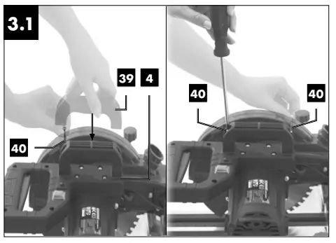
ATTENTION! The correct position of the transport handle (39) is specified by a groove.
- Mount the transport handle (39) on the machine head (4) using the Phillips screws 5.0 x 25 mm.
- Then tighten the two Phillips screws 5.0 x 25 mm (40) with a Phillips screwdriver (not included in the scope of delivery).
Setting up the machine 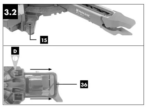
- The machine must be set up where it can stand securely.
- Secure the machine on a workbench, base frame or similar.
- Insert 4 screws (not included in the scope of delivery) into the holes on the fixed saw table (15).
- Tighten up the screws.
Installing the tilt protection
- Loosen the tilt protection (36) pre-installed at the bottom of the saw.
- Pull the tilt protection (36) out, so that it can still be fixed with the aid of the Allen screws.
- Secure the tilt protection again with an Allen key (D).
Setting the adjustment screw 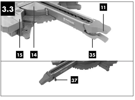
- Set the adjustment screw (37) to the level of the tabletop to avoid wobbling of the machine.
General information
- All covers and safety devices have to be properly fitted be-fore the equipment is switched on.
- It must be possible for the blade to run freely.
- When working with wood that has been processed before, watch out for foreign bodies such as nails or screws, etc.
- Before you press the ON/OFF switch check that the saw blade is fitted correctly. Moving parts must run smoothly.
- Before you connect the equipment to the power supply make sure the data on the rating plate are identical to the mains data.
Checking the moving saw blade guard safety device (5)
The saw blade guard protects against accidental contact with the saw blade and from chips flying around.
Check function
To do so, fold the saw downwards:
- The saw blade guard must provide free access to the saw blade without touching other parts.
- When folding the saw upwards into the starting position, the saw blade guard must cover the saw blade automatically.
Attachment
You need:
- 1x Allen key 6 mm (C)
- 1x Allen key 3 mm (D) (included in the scope of delivery)
- 1x open-ended spanner 13 mm
- 1x Phillips screwdriver (not included in the scope of delivery)
Attaching the multifunction sliding crosscut mitre saw
- In order to adjust the rotary table (14), fold the locking han-dle (11) upwards and pull up the latched position lever (35) with your index finger.
- Turn the rotary table (14) and pointer (12) to the desired angle measurement of the scale (13). To fix the setting, fold the locking handle (11) downwards.
- Press the machine head (4) lightly downwards and remove the locking bolt (23) from the motor bracket. Thus, the saw disengages from the lowest position.
- Swing the machine head (4) up.
- It is possible to secure the clamping devices (7) to the left or right on the fixed saw table (15). Insert the clamping devices (7) into the holes provided on the back of the stop rail (16) and secure them with the wing screws (7a).
For 0°- 45° mitre cuts, the clamping device (7) must only be mounted on the right side (see fig. 14-15). - It is possible to tilt the machine head (4) a max. 45° to the left by loosening the set screw (22).
- Workpiece supports (8) must always be secured and used during work. Define the desired table size (see 9.1.1.)
Defining the table size
- Loosen the set screw (9).
- Pull out the workpiece support (8) to the desired table size.
- Tighten the set screw (9) again.
Chip collection bag
The saw is equipped with a chip collection bag (17) for saw-dust and chips.
Attention! The chip collection bag may only be used when cutting wood and wood-like materials! When cutting metal, there is a risk that hot chips will ignite the chip collection bag. Squeeze the wings of the metal ring on the chip collection bag (17) together and slide it over the extraction port (17a) near the engine. The chip collection bag (17) can be emptied by means of a zipper at the bottom.
Connection to an external dust extractor
- Attach the extraction hose of a workshop vacuum cleaner to the extraction port (17a).
- The workshop vacuum cleaner must be suitable for the mate-rial being worked.
Attention! Always observe the safety and warning notices of the workshop vacuum cleaner being used. - When vacuuming dust that is especially detrimental to health or carcinogenic, use a special vacuum cleaner.
Precision adjustment of the stop for crosscut 90°
- No stop angle included.
- Lower the machine head (4) and secure it using the locking bolt (23).
- Loosen the set screw (22).
- Position the angle stop (A) between the saw blade (6) and the rotary table (14).
- Loosen the lock nut (26a).
- Adjust the adjusting screw (26) until the angle between the saw blade (6) and rotary table (14) is 90°.
- Re-tighten the lock nut (26a).
- Subsequently check the position of the angle indicator. If necessary, loosen the pointer (19) using a Philips screwdriver, set to position 0° on the angle scale (18) and re-tighten the retaining screw.
Precision adjustment of the stop for mitre cut 45°
- No stop angle included.
- Lower the machine head (4) and secure it using the locking bolt (23).
- Fix the rotary table (14) in the 0° position.
Attention! For mitre cuts (inclined saw head), the moveable stop rail (16a) must be fixed in the outer position (left side). - Open the set screw (16b) for the moveable stop rails (16a) and push the moveable stop rails (16a) outwards.
- The moveable stop rails (16a) must be locked so that the distance between the stop rails (16a) and the saw blade (6) is no more than 8 mm.
- The moveable stop rail (28) must be fixed in the inner posi-tion (right side).
- Before making the cut, check that no collision can occur be-tween the stop rails (16a) and the saw blade (6).
- Loosen the set screw (22) and use the handle (1) to angle the machine head (4) 45° to the left.
- 45° – position angle stop (B) between the saw blade (6) and rotary table (14).
- Loosen the lock nut (27a) and adjust the adjustment screw (27) until the angle between the saw blade (6) and the rotary table (14) is precisely 45°.
- Re-tighten the lock nut (27a).
- Subsequently check the position of the angle indicator. If necessary, loosen the pointer (19) using a Philips screwdriver, set to position 45° on the angle scale (18) and re-tighten the retaining screw.
Operation
Using the laser / LED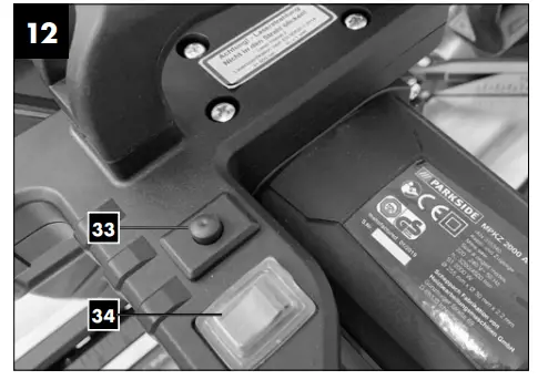
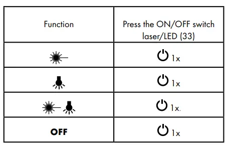
Changing the speed
The mitre saw has 2 speed ranges:
- To operate the mitre saw at a speed of 3200 rpm (metal), set the speed regulation switch (34) to position I.
- To operate the saw at a speed of 5000 rpm (wood), set the speed regulation switch (34) to position II.
Limiting the cutting depth (cutting grooves)
WARNING
Risk of kickback! When cutting grooves, it is particularly important that no lateral pressure is exerted on the saw blade. Otherwise, the saw head might suddenly kick back! Use a clamping device when cutting grooves. Avoid lateral pres-sure on the saw head.
- The cutting depth can be infinitely adjusted using the screw (24). To do this, loosen the knurled nut (24a) on the screw (24). Turn the screw (24) in or out to set the required cutting depth. Then re-tighten the knurled nut (24a) on the screw (24).
- Check the setting by completing a test cut.
Crosscut 90° and turntable 0°
In the case of cutting widths up to approx. 100 mm it is possible to fix the traction function of the saw with the set screw (20) in the rear position. In this position the machine can be operated in cross cutting mode. If the cutting width is over 100 mm then it is necessary to ensure that the set screw (20) is loose and the machine head (4) can move.
Attention! For 90° crosscuts, the moveable stop rail (16a) must be fixed in the inner position.
- Open the set screw (16b) for the moveable stop rails (16a) and push the moveable stop rails (16a) inwards.
- The moveable stop rails (16a) must be locked so that the distance between the stop rails (16a) and the saw blade (6) is no more than 8 mm.
- Before making the cut, check that no collision can occur be-tween the stop rails (16a) and the saw blade (6).
- Re-tighten the set screw (16b).
- Move the machine head (4) to its upper position.
- Use the handle (1) to push back the machine head (4) and fix it in this position if required (dependent on the cutting width).
- Place the piece of wood to be cut at the stop rail (16) and on the turntable (14).
- Secure the material with the clamping device (7) on the fixed saw table (15) to prevent it from shifting during the cutting process.
NOTE: Only use the left clamping device (7)! - Release the lock switch (3) and press the ON/OFF switch
(2) to start the motor. (Refer also to point 10.2 “Changing the speed” in this regard.) - With the drag guide (21) fixed in place (21): Use the handle (1) to move the machine head (4) steadily and with light pressure downwards until the saw blade (6) has completely cut through the work piece.
- With the drag guide (21) not fixed in place (21): Pull the machine head (4) all the way to the front. Lower the handle (1) to the very bottom by applying steady and light downward pressure. Now push the machine head (4) slowly and steadily to the very back until the saw blade (6) has completely cut through the work piece.
- When the cutting operation is completed, move the machine head back to its upper (home) position and release the ON/OFF button (2).
Attention! The machine executes an upward stroke auto-matically due to the return spring, i. e. do not release the han-dle (1) after completing the cut; instead allow the machine head to move upwards slowly whilst applying light counter pressure.
Crosscut 90° and turntable 0° – 45°
The multifunction sliding crosscut mitre saw can be used to make crosscuts of 0° -45° to the left and 0° -45° to the right in relation to the stop rail.
Attention! For 90° crosscuts, the moveable stop rail (16a) must be fixed in the inner position.
- Open the set screw (16b) for the moveable stop rails (16a) and push the moveable stop rails (16a) inwards.
- The moveable stop rails (16a) must be locked so that the distance between the stop rails (16a) and the saw blade (6) is no more than 8 mm.
- Before making the cut, check that no collision can occur be-tween the stop rails (16a) and the saw blade (6).
- Secure the set screw (16b) again.
- Loosen the locking handle (11) if tightened. Pull up the latched position lever (35) with your index finger and use the locking handle (11) to set the rotary table (14) to the desired angle (fig. 3.3+4).
- The pointer (12) on the rotary table must match the desired angle on the scale (13) on the fixed saw table (15).
- Re-tighten the locking handle (11) to secure the rotary table (14)(fig. 3.3+4).
- Cut as described under section 10.4.
Mitre cut 0°- 45° and turntable 0°
The multifunction sliding cross cut mitre saw can be used to make mitre cuts of 0° – 45° in relation to the work face. Attention! For 0°- 45° mitre cuts, the clamping device (7) must only be mounted on the right side (see fig. 14-15). Attention! For mitre cuts (inclined saw head), the moveable stop rail (16a) must be fixed in the outer position (left side).
- Open the set screw (16b) for the moveable stop rails (16a) and push the moveable stop rails (16a) outwards.
- The moveable stop rails (16a) must be locked so that the distance between the stop rails (16a) and the saw blade (6) is no more than 8 mm.
- The moveable stop rail (16a) must be fixed in the inner position (right side).
- Before making the cut, check that no collision can occur between the stop rails (16a) and the saw blade (6).
- Secure the set screw (16b) again.
- Move the machine head (4) to the top position.
- Fix the rotary table (14) in the 0° position.
- Loosen the set screw (22).
- Use the handle (1) to angle the machine head (4) to the left, until the pointer (19) indicates the desired angle measurement on the scale (18).
- Re-tighten the set screw (22).
- Cut as described in section 10.4.
Mitre cut 0°- 45° and turntable 0°- 45°
The multifunction sliding cross cut mitre saw can be used to make mitre cuts to the left of 0°- 45° in relation to the work face and, at the same time, 0° – 45° to the left or 0° – 45° to the right in relation to the stop rail (double mitre cut). Attention! For 0°- 45° mitre cuts, the clamping device (7) must only be mounted on the right side (see fig. 14-15). Attention! For mitre cuts (inclined saw head), the moveable stop rail (16a) must be fixed in the outer position (left side).
- Open the set screw (16b) for the moveable stop rails (16a) and push the moveable stop rails (16a) outwards.
- The moveable stop rails (16a) must be locked so that the distance between the stop rails (16a) and the saw blade (6) is no more than 8 mm.
- Before making the cut, check that no collision can occur be-tween the stop rails (16a) and the saw blade (6).
- Re-tighten the set screw (16b).
- Move the machine head (4) to its upper position.
- Fold the locking handle (11) upwards to loosen the rotary table (14) (fig. 3.3+4).
- Set the rotary table (14) to the desired angle (refer also to point 10.5 in this regard).
- Fold the locking handle (11) downwards to secure the rotary table (14) (fig. 3.3+4).
- Undo the set screw (22).
- Use the handle (1) to tilt the machine head (4) to the left until it coincides with the required angle value (in this connection see also section 10.6).
- Re-tighten the set screw (22).
- Cut as described under section 10.4.
Transport
- Tighten the locking handle (11) to lock the rotary table.
- Press the machine head (4) downwards and secure with the locking bolt (23).
- Fix the saw’s drag function with the locking screw for drag guide (20) in rear position.
- Carry the machine by the transport handle (39) and the fixed saw table (15).
- When reassembling the equipment proceed as described under section 8.
Maintenance
Warning! Prior to any adjustment, maintenance or service work disconnect the mains power plug!
General maintenance measures
Wipe chips and dust off the machine from time to time using a cloth. When cleaning the plastic do not use corrosive products.
Cleaning the moving saw blade guard safety device (5)
Always check the saw blade guard for debris before using the machine.
Remove old sawdust and splinters using a brush or similar tool.
Replacing the table insert
Danger!
With a damaged table insert (10) there is a risk of small parts getting stuck between table insert and saw blade, blocking the saw blade.
Immediately replace damaged table inserts!
- Swing the machine head (4) upwards and lock with the lock-ing bolt (23).
- Use one hand to insert the Allen key (C) in the flange screw (28).
- Firmly press the saw shaft lock (30) and slowly rotate the flange screw (28) in clockwise direction. The saw shaft lock (30) engages after no more than one rotation.
- Now, using a little more force, slacken the flange screw (29) in the clockwise direction.
- Turn the flange screw (28) right out and remove the outer flange (29).
- Fold the saw blade guard (5) upwards.
- Take the blade (6) off the inner flange (31) and pull out downwards.
- Carefully clean the flange screw (28), outer flange (29) and inner flange (31).
- Fit and fasten the new saw blade (6) in reverse order.
- Attention! The cutting angle of the teeth, in other words the direction of rotation of the saw blade (6) must coincide with the direction of the arrow on the housing.
- Before continuing your work make sure that all safety de-vices are in good working condition.
- Attention! Every time that you change the saw blade (6), check to see that it spins freely in the table insert (10, fig. 1) in both perpendicular and 45° angle settings.
- Attention! The work to change and align the saw blade (6) must be carried out correctly.
Adjusting the laser
If the laser (32) ceases to indicate the correct cutting line, you can readjust the laser.
- Loosen the Phillips screws (E).
- Set the laser by moving sideways until the laser beam strikes the teeth of the saw blade (6).
- Firmly secure both screws (E).
Brush inspection
Check the carbon brushes after the first 50 operating hours with a new machine, or when new brushes have been fitted. After carrying out the first check, repeat the check every 10 operating hours.
If the carbon is worn to a length of 6 mm, or if the spring or contact wire are burned or damaged, it is necessary to replace both brushes. If the brushes are found to be usable following removal, it is possible to reinstall them.
When servicing the carbon brushes, open the two latches coun-terclockwise (as shown in figure 20). Then remove the carbon brushes. Replace the carbon brushes in the reverse order.
Service information
Please note that the following parts of this product are sub-ject to normal or natural wear and that the following parts are therefore also required for use as consumables.
Wear parts*: carbon brushes, saw blade, table insert black (art. no. 5901215010), chip collection bagNot necessarily included in the scope of delivery!
Storage
Store the device and its accessories in a dark, dry and frost-proof place that is inaccessible to children. The optimum storage temperature is between 5 and 30˚C. Store the electrical tool in its original packaging.
Cover the electrical tool in order to protect it from dust and moisture. Store the operating manual with the electrical tool.
Electrical connection
The electrical motor installed is connected and ready for operation. The connection complies with the applicable VDE and DIN provisions. The customer’s mains connection, as well as the extension ca-ble used, must also comply with these regulations.
Important information
In the event of an overloading the motor will switch itself off. After a cool-down period (time varies) the motor can be switched back on again.
Damaged electrical connection cable
The insulation on electrical connection cables is often dam-aged. This may have the following causes:
- Passage points, where connection cables are passed through windows or doors.
- Kinks where the connection cable has been improperly fas-tened or routed.
- Places where the connection cables have been cut due to being driven over.
- Insulation damage due to being ripped out of the wall outlet.
- Cracks due to the insulation ageing.
Such damaged electrical connection cables must not be used and are life-threatening due to the insulation damage. Check the electrical connection cables for damage regularly. Make sure that the connection cable does not hang on the power network during the inspection.
Electrical connection cables must comply with the applicable VDE and DIN provisions. Only use connection cables of the same designation. The printing of the type designation on the connection cable is mandatory.
If the power cord of this device is damaged, it must be replaced by a special power cord, which is available from the manufac-turer or its service department.
AC motor
The mains voltage must be 220 – 240 V~.
- Extension cables up to 25 m long must have a cross-section of 1.5 mm2.
Connections and repairs of electrical equipment may only be carried out by an electrician. Please provide the following information in the event of any enquiries:
- Type of current for the motor
- Machine data – type plate
Disposal and recycling
The equipment is supplied in packaging to prevent it from be-ing damaged in transit. The raw materials in this packaging can be reused or recycled. The equipment and its accessories are made of various types of material, such as metal and plastic. Defective components must be disposed of as special waste. Ask your dealer or your local council. The packaging is wholly composed of environmentally-friendly materials that can be disposed of at a local recycling centre. Contact your local refuse disposal authority for more details of how to dispose of your worn-out electrical devices. Old devices must not be disposed of with household waste!
This symbol indicates that this product must not be dis-posed of together with domestic waste in compliance with the Directive (2012/19/EU) pertaining to waste electrical and electronic equipment (WEEE). This product must be disposed of at a designated collection point. This can occur, for example, by handing it in at an authorised col-lecting point for the recycling of waste electrical and electronic equipment. Improper handling of waste equipment may have negative consequences for the environment and human health due to potentially hazardous substances that are often contained in electrical and electronic equipment. By properly disposing of this product, you are also contributing to the ef-fective use of natural resources. You can obtain information on collection points for waste equipment from your municipal administration, public waste disposal authority, an authorised body for the disposal of waste electrical and electronic equip-ment or your waste disposal company.
Troubleshooting
| Fault | Possible cause | Remedy |
| Motor does not work | Motor, cable or plug defective, the mains circuit breaker switched off | Arrange for inspection of the machine by a specialist. Never repair the motor yourself. Danger!
Check fuses and replace as necessary. |
| The motor starts up slowly and does not reach operating speed. | Voltage too low, coils damaged, capacitor burnt | Contact an electrician to check the voltage. Arrange for inspection of the motor by a specialist.
Arrange for replacement of the capacitor by a special- ist. |
| Motor makes excessive noise | Coils damaged, motor defective | Arrange for inspection of the motor by a specialist |
| The motor does not reach its full power. | Circuits in the network are overloaded (lamps, other motors, etc.) | Do not use any other equipment or motors on the same circuit |
| Motor overheats easily. | Overloading of the motor, insufficient cooling of the motor | Avoid overloading the motor while cutting, remove dust from the motor in order to ensure optimal cooling of the motor |
| Saw cut is rough or wavy | Saw blade dull, tooth shape not appropriate for the material thickness | Re-sharpen saw blade and/or use suitable saw blade |
| Workpiece pulls away and/or splinters | Excessive cutting pressure and/or saw blade not suitable for use | Insert suitable saw blade |
Warranty certificate
Dear Customer,
All of our products undergo strict quality checks to ensure that they reach you in perfect condition. In the unlikely event that your device develops a fault, please contact our service department at the address shown on this guarantee card. Of course, if you would prefer to call us then we are also happy to offer our assistance under the service number printed below. Please note the following terms under which guarantee claims can be made:
- These guarantee terms cover additional guarantee rights and do not affect your statutory warranty rights. We do not charge you for this guarantee.
- Our guarantee only covers problems caused by material or manufacturing defects, and it is restricted to the rectification of these de-fects or replacement of the device. Please note that our devices have not been designed for use in commercial, trade or industrial ap-plications. Consequently, the guarantee is invalidated if the equipment is used in commercial, trade or industrial applications or for other equivalent activities. The following are also excluded from our guarantee: compensation for transport damage, damage caused by failure to comply with the installation/assembly instructions or damage caused by unprofessional installation, failure to comply with the operating instructions (e.g. connection to the wrong mains voltage or current type), misuse or inappropriate use (such as overload-ing of the device or use of non-approved tools or accessories), failure to comply with the maintenance and safety regulations, ingress of foreign bodies into the device (e.g. sand, stones or dust), effects of force or external influences (e.g. damage caused by the device being dropped) and normal wear resulting from proper operation of the device. The guarantee is rendered null and void if any attempt is made to tamper with the device.
- The guarantee is valid for a period of 3 years starting from the purchase date of the device. Guarantee claims should be submitted before the end of the guarantee period within two weeks of the defect being noticed. No guarantee claims will be accepted after the end of the guarantee period. The original guarantee period remains applicable to the device even if repairs are carried out or parts are replaced. In such cases, the work performed or parts fitted will not result in an extension of the guarantee period, and no new guarantee will become active for the work performed or parts fitted. This also applies when an on-site service is used.
- In order to assert your guarantee claim, please contact the service partner shown below. If the complaint is within the guarantee pe-riod, we will provide you with a return slip, with which you can return your defective device free of charge to us. It would help us if you could describe the nature of the problem in as much detail as possible. If the defect is covered by our guarantee then your device will either be repaired immediately and returned to you, or we will send you a new device.
Of course, we are also happy offer a chargeable repair service for any defects which are not covered by the scope of this guarantee or for units which are no longer covered. To take advantage of this service, please send the device to our service address.
Service-Hotline (GB):
+800 4003 4003
(0,00 EUR/Min.)
Service-Email (GB):
[email protected]
Service Address (GB):
Forest Park & Garden
Coed Court, Taffsmead Road
Treforest, Ind. Estate, Pontypridd CF375SW
At www.lidl-service.com you can download this and many more manuals, product videos plus installation software.
The QR code takes you directly to the Lidl service page (www.lidl-service.com) and you can open your operating manual by entering the article number (IAN) 360564_2010.