![]()
Keypad 2nd Generation
Z-Wave™ Technical Manual
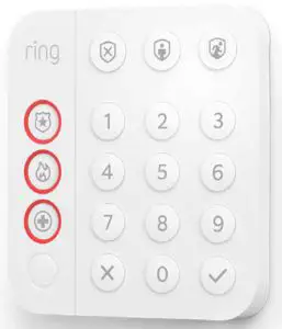
Ring Keypad
Introduction
Ring Alarm Keypad is a wireless accessory for the Ring Alarm system which provides users the ability to arm and disarm their system, view system status, and manage alarm conditions. After installing the Keypad and setting up the Keypad in the Ring app, perform arming and disarming actions as well as receive system indications for different status updates and events. The Ring Alarm Base Station is required to enable Keypad features and functions within the Ring app.
Notes:
- This product can be operated in any Z-Wave™ network with other Z-Wave certified devices from other manufacturers. All mains operated nodes within the network will act as repeaters regardless of vendor to increase reliability of the network.
- SmartStart enabled products can be added into a Z-Wave network by scanning the ZWave QR Code present on the product with a controller providing SmartStart inclusion. No further action is required and the SmartStart product will be added automatically within 10 minutes of being switched on in the network vicinity.
Installation and Set-Up
Ring Alarm Keypad – Basic Setup & Installation
In-app Setup
- Ensure your Ring Alarm system is disarmed.
- In the Ring app, tap Set Up a Device and find the Keypad in the Security Devices menu.
- Follow the in-app instructions to complete setup. Plug in the Keypad to trigger setup mode.
Installation
- Choose a location for installing the Keypad.
- Use the provided bracket and place the Keypad on a flat surface. For wall mounting, use the screws and anchors to secure the bracket to the wall and slide the Keypad into place.
- Using the provided double-sided tape, peel the backing and attach the Motion Detector to the mounting location.
Note
This product can be operated in any Z-Wave network with other Z-Wave certified devices from other manufacturers. All mains operated nodes within the network will act as repeaters regardless of vendor to increase reliability of the network.
This is a SmartStart enabled product which can be added into a Z-Wave network by scanning the Z-Wave QR Code present on the product with a controller providing SmartStart inclusion. No further action is required and the SmartStart product will be added automatically within 10 minutes of being switched on in the network vicinity. This product can also be operated in any Z-Wave network with other Z-Wave certified devices from other manufacturers.
Z-Wave Instructions
Z-Wave Device Type: Entry Control Keypad
Role Type: Listening Sleeping Slave
GENERIC_TYPE_ENTRY_CONTROL (0x40)
SPECIFIC_TYPE_SECURE_KEYPAD (0x0B)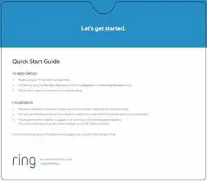
Ring Alarm Keypad – Inclusion
Adding Ring Alarm Keypad to a Z-Wave Network
Ring Alarm Keypad can be added via SmartStart or Classic inclusion mode.
Note
When prompted for the QR Code or PIN, you may find them on the device, on the box, or on a card inside the box. Keep the device nearby. You’ll be prompted plug the device in to power on the device and enter setup mode.
SmartStart Inclusion Steps:
- Initiate the add flow for Security Devices in the Ring mobile application – Follow the guided add flow instructions provided in the Ring mobile application.
- When prompted by the mobile application, scan the QR code found on the package of the Keypad. The QR code can also be found on the device itself.
- Using the power adapter and cable provided, plug the Keypad into a standard outlet and the device will go into SmartStart inclusion mode. While in this mode, Keypad can be added to a Z-Wave controller that supports SmartStart. When in SmartStart inclusion mode, SmartStart can be restarted by tapping the button on the front of the device.
Classic Inclusion Steps:
Classic Inclusion should be used if the controller does not support SmartStart.
- Initiate add flow for Security Devices in the Ring mobile application – Follow the guided add flow instructions provided in the Ring mobile application.
- Select add manually and enter the 5-digit DSK PIN found on the package of the Ring Alarm Keypad or the 5-digit DSK PIN found under the QR code on the device. After powering on the device, press and hold the #1 button for ~3 seconds. Release the button and the device will enter Classic inclusion mode which implements both classic inclusion with a Node Information Frame, and Network Wide Inclusion. During Classic Inclusion mode, the green Connection LED will blink three times followed by a brief pause, repeatedly. When Classic inclusion times-out, the device will blink alternating red and green a few times.
| LED Behabior for Inclusion | Blink Pattern |
| SmartStart Started | Green LED three times, repeated after a brief pause |
| Classic Inclusion Started | Green LED three times, repeated after a brief pause |
| Classic Inclusion Timed-Out | Alternate red and green a few times |
| Inclusion Successful (Authenticated S2) | Green LED on solid |
| Inclusion Not Successful (Self-Destruct) | Red LED on solid |
Ring Alarm Keypad – Exclusion
Removing Ring Alarm Keypad from a Z-Wave Network
Exclusion Instructions:
- Initiate remove “Ring Alarm Keypad” flow in the Ring Alarm mobile application – Select the settings icon from device details page and choose “Remove Device” to remove the device. This will place the controller into Remove or “Z-Wave Exclusion” mode.
- Locate the pinhole reset button on the back of the device.
- With the controller in Remove (Z-Wave Exclusion) mode, use a paper clip or similar object and tap the pinhole button. The device’s Connection LED turns on solid red to indicate the device was removed from the network.
Ring Alarm Keypad – Factory Reset
Factory Default Instructions
- To restore Ring Alarm Keypad to factory default settings, locate the pinhole reset button on the device. This is found on the back of the device after removing the back bracket.
- Using a paperclip or similar object, insert it into the pinhole, press and hold the button down for 10 seconds.
- The device’s Connection icon LED will rapidly blink green continuously for 10 seconds. After about 10 seconds, when the green blinking stops, release the button. The red LED will turn on solid to indicate the device was removed from the network.
Note
Use this procedure only in the event that the network primary controller is missing or otherwise inoperable.
Wake-Up Notification
Not applicable. Ring Alarm Keypad (LSS) is a Frequently Listening Receiver Slave (FLiRS) device and does not support Wake Up Command Class.
Z-Wave Command Classes
| Command Class | Version | Required Security Class |
| Association | 2 | Highest granted |
| Association Group Information | 3 | Highest granted |
| Device Reset Locally | 1 | Highest granted |
| Firmware Update Meta Data | 5 | Highest granted |
| Indicator | 3 | Highest granted |
| Manufacturer Specific | 2 | Highest granted |
| Multi-Channel Association | 3 | Highest granted |
| Powerlevel | 1 | Highest granted |
| Security 2 | 1 | none |
| Security 0 | 1 | none |
| Supervision | 1 | none |
| Transport Service | 2 | none |
| Version | 3 | Highest granted |
| Z-Wave Plus Info | 2 | none |
| Notification | 8 | Highest granted |
| Configuration | 4 | Highest granted |
| Battery | 2 | Highest granted |
| Entry Control | 1 | Highest granted |
Association Command Class
| Group Identifier | Max Nodes | Description |
| 1 (Lifeline) | 0x05 | 1. Notification Report a. See notification CC section for notifications that are sent 2. Entry Control Notification 3. Battery Report 4. Device Reset Locally Notification |
Configuration Command Class
The Keypad has the following supported configuration parameters.
| Parameter Number |
Description | Number of Bytes |
Default | Min | Max | Format |
| 1 | Heartbeats: This parameter is the number minutes between heartbeats. Heartbeats are automatic battery reports on a timer after the last event. | 1 | 70 (0x46) | 1 (0x01) | 70 (0x46) | 1 |
| 2 | Number of application level retries attempted for messages either not ACKed or messages encapsulated via supervision get that did not receive a report. | 1 | 1 (0x01) | 0 (0x00) | 5 (0x05) | 2 |
| 3 | Application Level Retry Base Wait Time Period: The number base seconds used in the calculation for sleeping between retry messages. | 1 | 5 (0x05) | 1 (0x01) | 60 (0x3C) | 3 |
| 4 | Announcement Audio Volume (for audio files – should this be lumped into one of the other volume settings?) | 1 | 7 | 0 | 210 | 4 |
| 5 | Key Tone Volume | 1 | 6 | 0 | 10 | 5 |
| 6 | Siren Volume | 1 | 10 | 0 | 10 | 6 |
| 7 | Long press emergency duration (seconds) This parameter allows a user to configure the duration in seconds for the hold time required to capture a long press . This includes Emergency Buttons + Mode Buttons (Police, Fire, Medical, Disarmed, Home, Away) | 1 | 3 | 2 | 5 | 7 |
| 8 | Long press number pad duration (seconds) This parameter allows a user to configure the duration in seconds for the hold time required to capture a long press . This includes Number Pad + Check & X (0-9, Check, X) | 1 | 3 | 2 | 5 | 8 |
| 9 | Proximity Display Timeout : Timeout in seconds when proximity is detected and no input is received | 1 | 5 | 0 | 30 | 9 |
| 10 | Button Press Display Timeout : Timeout in seconds when any button is pressed, but a sequence is not completed and buttons are no longer being pressed | 1 | 5 | 0 | 30 | 10 |
| 11 | Status Change Display Timeout: Timeout in seconds when indicator command is received from the hub to change status | 1 | 5 | 0 | 30 | 11 |
| 12 | Security Mode Brightness: Adjusts the brightness of the security mode buttons | 1 | 100 | 0 | 100 | 12 |
| 13 | Key Backlight Brightness: Adjusts the brightness of the keypad backlight. Used for Key Backlight LEDs only Available settings: 0-100% | 1 | 100 | 0 | 100 | 13 |
| 14 | Ambient Light Sensor Level: Light threshold where keypad will stop backlighting if higher than | 1 | 5 | 0 | 100 | 14 |
| 15 | Proximity On/OFF: Turn On and Off the Proximity Detection. |
1 | 1 | 0 | 1 | 15 |
| 16 | Ramp Time Config: Ramp time in milliseconds to turn the LEDs on/off. Applies to all LEDs on the keypad | 1 | 50 | 0 | 255 | 16 |
| 17 | Low Battery Threshold – The percentage level at which the display would turn on the yellow battery indicator (whenever the display is on). | 1 | 15 | 0 | 100 | 17 |
| 18 | Languages Set: bit number in the languages supported bitmask to set | 1 | 3 0 (US English) | 0 | 31 | 18 |
| 19 | Warn Battery Threshold – The percentage level at which the display would turn on the red battery indicator (whenever the display is on). | 1 | 5 | 0 | 100 | 19 |
| 20 | The number of milliseconds waiting for a Supervisory Report response to a Supervisory Get encapsulated command from the device before attempting a retry. | 2 | 1500 (0x5DC) | 500 (0x1F4) | 5000 (0x1388) |
20 |
| 21 | System Security Mode Display: (Always, Sometimes, Never). • 601 = Always On • 1 – 600 = periodic interval • 0 = Always |
2 | 0 | 0 | 601 | 21 |
| 22 | Languages Supported (Get): returns bitmask of languages supported. Bits set to 1 indicate that the language is supported | 4 | N/A | N/A | N/A | 22 |
Notification Command Class, V8
| Sensor Condition | Command Class and Value | Association Group |
| AC mains power reconnected | Notification Report Type: 0x08 Power Management State: 0x03 AC mains reconnected |
1 (Lifeline) |
| AC mains power disconnected | Notification Report Type: 0x08 Power Management State: 0x02 AC mains disconnected |
1 (Lifeline) |
| Watchdog Notification | Notification Report Type: System 0x09 State Value: 0x04 System Software Failure State Parameter Value = Ox55 |
1 (Lifeline) |
| Software Fault (Ring) | Notification Report Type: System 0x09 State Value: 0x04 System Software Failure State Parameter Value = OxAA (Ring Value for Soft Fault) |
1 (Lifeline) |
| Software Fault (SDK) | Notification Report Type: System 0x09 State Value: 0x04 System Software Failure State Parameter Value = OxA9 (SDK Value for Soft Fault) |
1 (Lifeline) |
| Software Reset (Not triggered by failure) | Notification Report Type: System 0x09 State Value: 0x04 System Software Failure State Parameter Value = OxAC |
1 (Lifeline) |
| Power On Reset | Notification Report Type: Ox08 Power Management Event Parameter: Ox01 Power has been applied |
1 (Lifeline) |
| Brownout | Notification Report Type: 0x08 Power Management Event: 0x05 Voltage Drop/Drift |
1 (Lifeline) |
| Pin Reset (soft reset) | Notification Report Type: System 0x09 State Value: 0x04 System Software Failure State Parameter Value = OxAB |
1 (Lifeline) |
| Dropped Frame | Yes, via Notification Set of Notification Type 0x07, and status of 0x00: This type of notification turned off 0xFF: This type of notification turned on |
1 (Lifeline) |
Supplier’s Declaration of Conformity – Compliance Information Statement
Unique Identifier: Ring Contact Sensor
Responsible Party and Party issuing Supplier’s Declaration of Conformity
Ring LLC dba Ring
1523 26th Street
Santa Monica, CA 90404 U.S.A.
www.ring.com / [email protected]
FCC Compliance Statement (for products subject to Part 15)
This device complies with Part 15 of the FCC Rules. Operation is subject to the following two conditions: (1) This device may not cause harmful interference, and (2) this device must accept any interference received, including interference that may cause undesired operation.
NOTE: This equipment has been tested and found to comply with the limits for a Class B digital device, pursuant to Part 15 of the FCC Rules. These limits are designed to provide reasonable protection against harmful interference in a residential installation. This equipment generates, uses, and can radiate radio frequency energy and, if not installed and used in accordance with the instructions, may cause harmful interference to radio communications.
However, there is no guarantee that interference will not occur in a particular installation. If this equipment does cause harmful interference to radio or television reception, which can be determined by turning the equipment off and on, the user is encouraged to try to correct the interference by one or more of the following measures:
- Reorient or relocate the receiving antenna.
- Increase the separation between the equipment and receiver.
- Connect the equipment into an outlet on a circuit different from that to which the receiver is connected.
- Consult the dealer or an experienced radio/TV technician for help.
Innovation, Science and Economic Development Canada (ISED) Compliance
This device contains licence-exempt transmitter(s)/ receiver(s) that comply with Innovation, Science and Economic Development Canada’s licence-exempt RSS(s). Operation is subject to the following two conditions:
- This device may not cause interference.
- This device must accept any interference, including interference that may cause undesired operation of the device.
CAN ICES-3 (B)/NMB-3(B)
In accordance with FCC requirements of human exposure to radio frequency fields, the radiating element shall be installed such that a minimum separation distance of 20 cm is maintained from the general population.
WARNING: Changes or modifications to this unit not expressly approved by the party responsible for compliance could void the user’s authority to operate the equipment.
CAUTION: To reduce the risk of electrical shock, DO NOT open the unit. There are no user serviceable parts inside the unit. Refer to customer support for any repairs.
CAUTION: Danger of explosion if battery is incorrectly replaced. Replace only with the same or equivalent type recommended by the manufacturer. Dispose of the used batteries according to the manufacturer’s instructions.
To review your warranty coverage, please visit www.ring.com/warranty.
© 2020 Ring LLC or its affiliates.
Ring, Always Home, and all related logos are trademarks of Ring LLC or its affiliates.