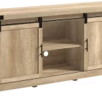
sauder Crossmill 3 Shelf Bookcase with Doors Instructions
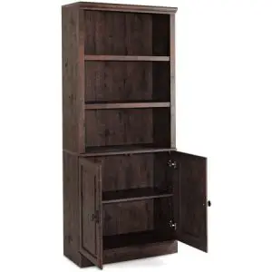
Model: 418735
Here’s one for the books.
CONTACT US FIRST BEFORE MAKING ANY RETURNS TO THE STORE.
Visit sauder.com/service to order replacement parts, view video assembly tips, or chat with a live rep. Prefer the phone? Give us a ring at 1-800-523-3987.
Customer Service is available Monday-Friday – 9 a.m. to 5:30 p.m. EST (except holidays)
NOTE: THIS INSTRUCTION BOOKLET CONTAINS IMPORTANT SAFETY INFORMATION.
PLEASE READ AND KEEP FOR FUTURE REFERENCE.
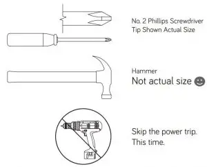
Assembly Tools Required
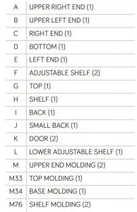
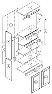
Part Identification
While not all parts are labeled, some of the parts will have a label or an inked letter on the edge
to help distinguish similar parts from each other. Use this part identification to help identify similar parts.
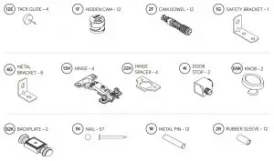
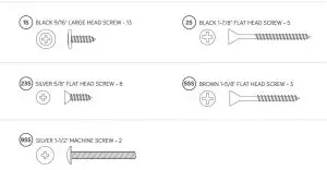
Hardware Identification
Screws are shown actual size. You may receive extra hardware with your unit.
Assembly
Step 1
Look for this icon. It means a video assembly tip is available at www.sauder.com/service/tips
- Assemble your unit on a carpeted fl oor or on the empty carton to avoid scratching your unit or the fl oor.
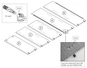
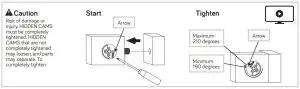
- Push twelve HIDDEN CAMS (1F) into the ENDS (A, B, C, and E) and BOTTOM (D). Then, insert the metal end of a CAM DOWEL (2F) into each HIDDEN CAM.
Do not tighten the HIDDEN CAMS in this step.
Step 2
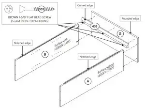
- Fasten the UPPER ENDS (A and B) to the TOP (G). Tighten four HIDDEN CAMS.
- Fasten the TOP MOLDING (M33) to the TOP (G). Use three BROWN 1-5/8″ FLAT HEAD SCREWS (55S).
- NOTE: Do not over tighten the SCREWS into the TOP.
![]()
Do not stand the unit upright without the BACK fastened. The unit may collapse.
Step 3
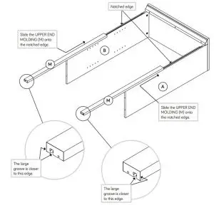
- Slide the UPPER END MOLDINGS* (M) onto the notched edges of the UPPER ENDS (A and B).
- *U.S. Patent No. 5,499,886
Just think. The sooner you do this, the sooner you do something else.
Step 4
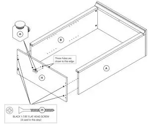
- Fasten the SHELF (H) to the UPPER ENDS (A and B). Use four BLACK 1-7/8″ FLAT HEAD SCREWS (2S).
- Push two DOOR STOPS (4I) into the holes in the SHELF (H)
Step 5
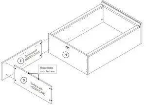
- Fasten the LEFT END (E) to the SHELF (H). Tighten two HIDDEN CAMS.
- Fasten the BOTTOM (D) to the LEFT END (E). Tighten two HIDDEN CAMS.
Step 6
- Fasten the RIGHT END (C) to the BOTTOM (D) and SHELF (H). Tighten four HIDDEN CAMS.
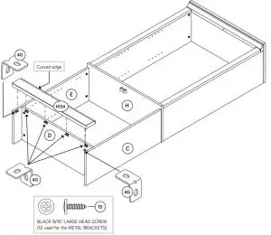
- Fasten six METAL BRACKETS (4G) to the ENDS (C and E) and BOTTOM (D). Use six BLACK 9/16″ LARGE HEAD SCREWS (1S).
- NOTE: Be sure the edges of the METAL BRACKETS are even with the edges of the ENDS and BOTTOM.
- Fasten the BASE MOLDING (M34) to the ENDS (C and E) and BOTTOM (D). Use six BLACK 9/16″ LARGE HEAD SCREWS (1S) through the METAL BRACKETS on the ENDS and BOTTOM and into the BASE MOLDING.
Step 7
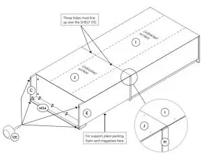
- Carefully turn your unit over onto its front edges. Unfold the BACK (I) and lay it over your unit.
- Make equal margins along all four edges of the BACK (I). Push on opposite corners of your unit if needed to make it “square”.
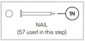
- Fasten the BACK (I) to your unit using the NAILS (1N).
- NOTE: Do not tap NAILS into the holes that line up over the SHELF (H) at this time.
- Fasten the SMALL BACK (J) to your unit using the NAILS (1N).
- NOTE: The SMALL BACK (J) overlaps the BACK (I). Be sure to tap nails in the holes that line up over the SHELF (H).
- Using your hammer, gently tap four TACK GLIDES (12E) into the bottom edges of the ENDS (C and E) and BASE MOLDING (M34).
![]()
Do not stand the unit upright without the BACK fastened. The unit may collapse.
Step 8
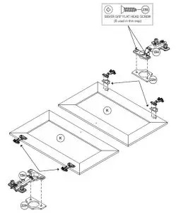
- Place four HINGE SPACERS (22H) over the large holes in the DOORS (K).
- Fasten four HINGES (13H) to the DOORS (K). Use eight SILVER 5/8″ FLAT HEAD SCREWS (23S).
Step 9
- Carefully stand your unit upright.
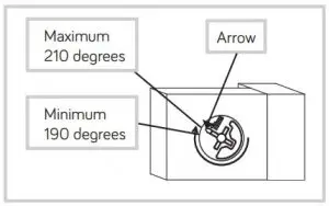
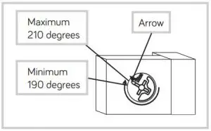
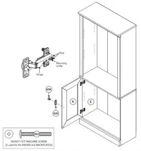
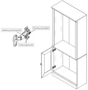
- Before fastening the DOOR to your unit, be sure the mounting screw is against the stops as shown in the diagram. If it isn’t, loosen the mounting screw to slide it against the stops. Then tighten the mounting screw.
- Fasten a DOOR (K) to the LEFT END (E) as shown in the lower diagram. Use the screws in the HINGES. You should start each SCREW a few turns before completely tightening any of them.
- Fasten a KNOB (69K) and BACKPLATE (92K) to the DOOR (K). Use a SILVER 1-1/2″ MACHINE SCREW (95S).
- Repeat this step for the other DOOR (K).
- See the next step for DOOR adjustments.
Pro Tip: Lift with your legs. And, you know, your arms.
Step 10
- Refer to the enlarged diagram to identify the parts on the HINGES.
- The DOORS may need some adjustments. Follow the text below to make needed adjustments.
- DOOR ADJUSTMENTS: To adjust the DOORS from side to side (horizontal), turn the adjusting screw in or out.
- To adjust the DOORS up and down (vertical), loosen both vertical adjustment screws. Move the DOORS up or down to the desired location. Tighten the screws after making adjustments.
- To adjust the DOORS in or out (depth), loosen the mounting screw one turn and move the DOORS in or out, as needed. Tighten the mounting screw after making adjustments.
Step 11
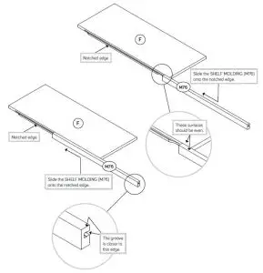
- Slide the SHELF MOLDINGS* (M76) onto the notched edges of the ADJUSTABLE SHELVES (F).
- NOTE: Center the SHELF MOLDINGS on the ADJUSTABLE SHELVES.
- *U.S. Patent No. 5,499,886
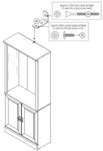
Step 12
- We recommend using the SAFETY BRACKET (1G) for added stability. Use a BLACK 9/16″ LARGE HEAD SCREW (1S) into the top of the unit and a BLACK 1-7/8″ FLAT HEAD SCREW (2S) into a stud in your wall.
Step 13
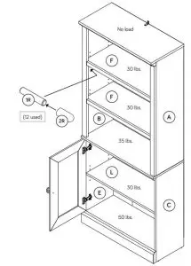
- Push the RUBBER SLEEVES (2R) over the METAL PINS (1R). Insert the METAL PINS into the hole locations of your choice in the ENDS (A, B, C, and E). Set the ADJUSTABLE SHELVES (F and L) onto the METAL PINS.
- NOTE: Please read the back pages of the instruction booklet for important safety information.
- This completes assembly. Clean with a damp cloth. Wipe dry.
And to celebrate, why not share your success story at Walmart.com or

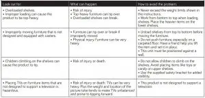
Please use your furniture correctly and safely. Improper use can cause safety hazards, or damage to your furniture or household items. Carefully read the following chart.
1-YEAR LIMITED WARRANTY
- Sauder Woodworking Co. (Sauder®) provides limited warranty coverage to the original purchaser of this product for a period of one year from the date of purchase against defects in materials or workmanship of Sauder furniture components. As used in this Warranty, “defect” means imperfections in components which substantially impair the utility of the product. This Warranty gives you specific legal rights, and you may also have other rights which vary from state to state.
- There is no warranty coverage for defects or conditions that result from the failure to follow product assembly instructions, information or warnings, misuse or abuse, intentional damage, fire, flood, alteration or modification of the product, or use of the product in a manner inconsistent with its intended use, nor any condition resulting from incorrect or inadequate maintenance, cleaning, or care. There is also no warranty coverage for rented products or any products purchased “used” or “as is”, at a distress or going-out-of business sale, or from a liquidator.
- As the exclusive remedy under this Warranty, Sauder will (at its sole option) repair, replace or refund the value of any defective furniture component. Sauder may require independent confi rmation of the claimed defect and proof of purchase. Replacement parts will be warranted for only the remaining period of the original Warranty. SAUDER SHALL HAVE NO LIABILITY for ANY INCIDENTAL OR CONSEQUENTIAL DAMAGES OF ANY KIND and all such damages are EXCLUDED FROM THIS WARRANTY, such as loss of use, disassembly, transportation, labor or damage to property on or near the product. Some states do not allow the exclusion or limitation of incidental or consequential damages, so the above limitation or exclusion may not apply to you.
- This Warranty applies only to warranted defects that fi rst arise and are reported to Sauder within the warranty coverage period. The Warranty cannot be transferred to subsequent owners or users of the product, and it shall be immediately void in the event the product is resold, transferred, leased or rented to any third party or person other than the original purchaser.
- THERE ARE NO OTHER WARRANTIES APPLICABLE TO THIS PRODUCT. Under
the laws of certain states, there may be no implied warranties from Sauder and all implied warranties, INCLUDING ANY IMPLIED WARRANTY OF MERCHANTABILITY OR FITNESS FOR A PARTICULAR PURPOSE are disclaimed where allowed by law. TO THE EXTENT ANY IMPLIED WARRANTIES ARE APPLICABLE, ANY IMPLIED WARRANTIES, INCLUDING ANY IMPLIED WARRANTY OF MERCHANTABILITY OR FITNESS FOR A PARTICULAR PURPOSE, ARE LIMITED IN DURATION TO THE DURATION OF THIS EXPRESS WARRANTY or the minimum period allowed by law, whichever is shorter. Some states do not allow limitations on how long an implied Warranty lasts, so the above limitation may not apply to you. - For Warranty inquiries or claims, please visit our website www.sauder.com. You can also contact Sauder at 1.800.523.3987. Sauder may require Warranty claims to be submitted in writing to: Sauder Woodworking Co., 502 Middle Street, Archbold, OH 43502 USA. Please include your sales receipt or other proof of purchase and a specific description of the product defect.
If you need assistance please contact customer service at 800-523-3987 Monday-Friday – 9 a.m. to 5:30 p.m. EST (except holidays) or at sauder.com/service.

So, how did it go?
Set a world record for speed?
Feeling good about yourself?
Nice. Get social with it on any of these quality share sites.

General Conformity Certificate
- This certificate applies to the Sauder Woodworking Product identified by this Instruction Book.
- This certificate applies to compliance of this product with the CPSC Ban on Lead-Containing Paint (16 CFR 1303).
- This product is manufactured by:
Sauder Woodworking Company
502 Middle St.
Archbold, OH 43502
419-446-2711 - Date of Manufacture