CONTACT US FIRST
BEFORE MAKING ANY RETURNS TO THE STORE.
Visit sauder.com/service to order replacement parts, view video assembly tips, or chat with a live rep.
Prefer the phone? Give us a ring at 1-800-523-3987.
Customer Service is available Monday-Friday – 9 a.m. to 5:30 p.m. EST (except holidays)
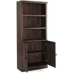
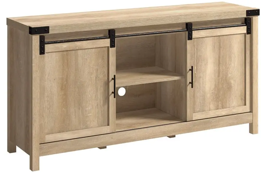
TV Stand
Model 411660
 It stands. You sit.
A thing of beauty, this one.
 Share your journey!
NOTE: THIS INSTRUCTION BOOKLET CONTAINS IMPORTANT SAFETY INFORMATION.
PLEASE READ AND KEEP FOR FUTURE REFERENCE.
Lot # 530097 05/28/19
Purchased: ____
Assembly Tools Required
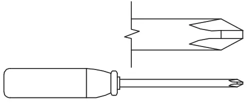 |
No. 2 Phillips Screwdriver Tip Shown Actual Size |
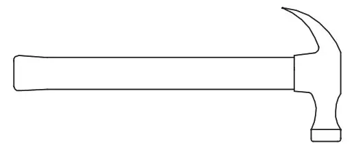 |
Hammer Not actual size  |
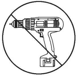 |
Skip the power trip. This time. |
 WARNING
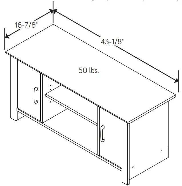
The use of a TV that is too heavy or large is hazardous. A TV that is too heavy will create a risk of a tip-over that can cause severe injury or death. A TV that is too large for the available space might be accidentally pushed or bumped off the furniture, or subject to tip-over.
- Check the size and weight of your TV. Compare it to the diagram below – before you begin assembly!
- This Sauder unit is designed for use with televisions weighing less than 50 pounds. Never use a TV that weighs more.
- The size of the television, front-to-back and side-to-side, must fi t within the space defi ned in the diagram.
- Never place the front edge of the TV past the front edge of the TV support shelf (or stop molding – if equipped)
- Never allow the sides of the TV to extend past the side edges of the TV support surface.
- If the TV has a CRT picture tube, the picture tube cone may extend past the rear of the support shelf.
- Be sure to apply the warning label as instructed in the last assembly step. The label provides important safety-related information.
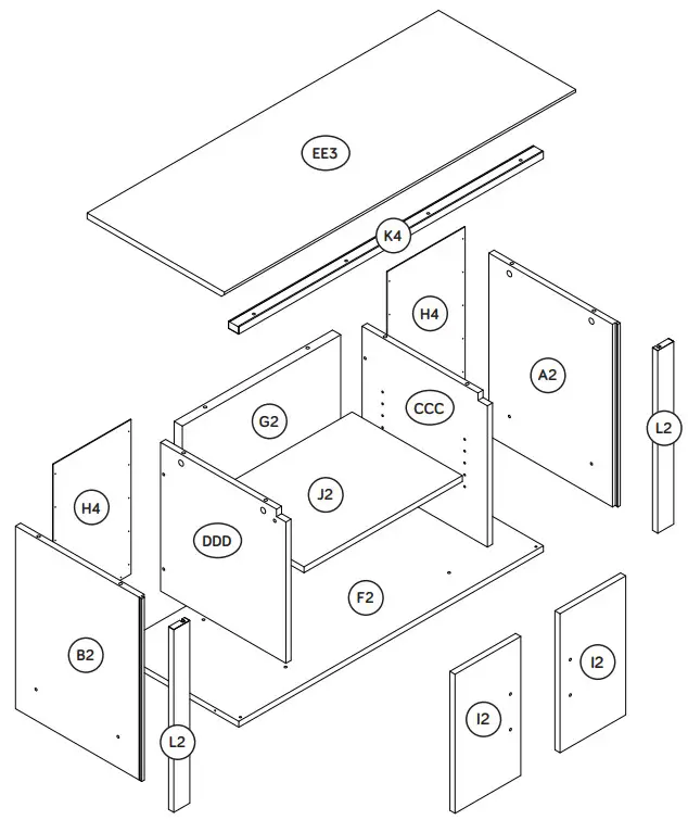
Part Identification
♦While not all parts are labeled, some of the parts will have a label or an inked letter on the edge to help distinguish similar parts from each other. Use this part identifi cation to help identify similar parts.
| A2 B2 CCC DDD |
RIGHT END (1) LEFT END (1) RIGHT UPRIGHT (1) LEFT UPRIGHT (1) |
EE3 F2 G2 H4 |
TOP (1) BOTTOM (1) CENTER BACK (1) BACK (2) |
I2 J2 K4 L2 |
DOOR (2) ADJUSTABLE SHELF (1) VALANCE (1) END MOLDING (2) |
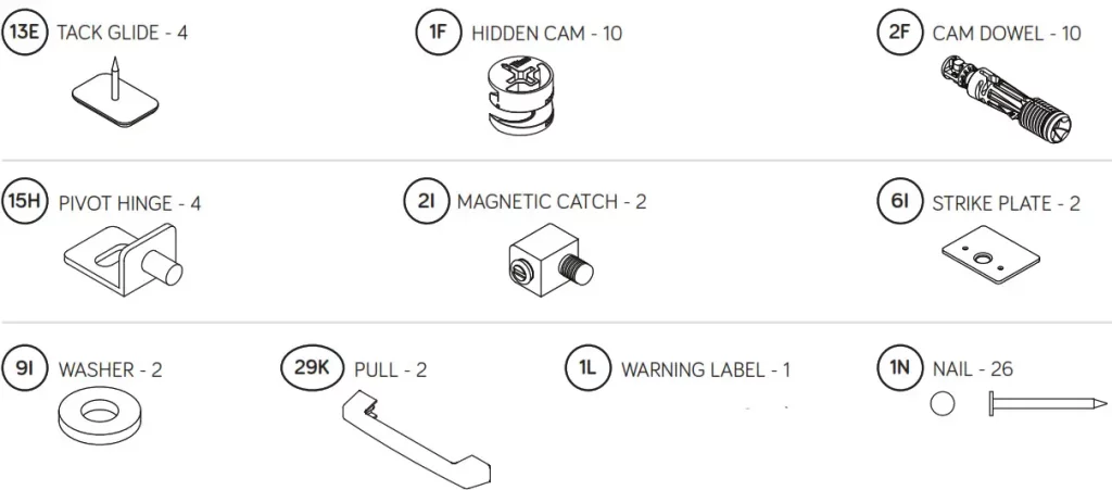
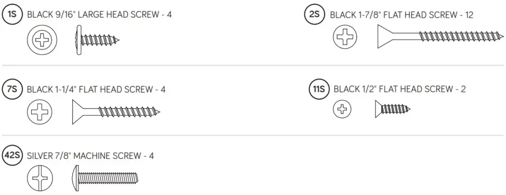
♦Screws are shown actual size. You may receive extra hardware with your unit.
| Never use this furniture with a TV that is too large or too heavy. Severe injury or death can occur. The TV and furniture will be unstable and may tip. -The TV must be less than 50 lbs. -The base of the TV must be able to sit completely on this shelf. Refer to the instruction book for complete safety information. Note: This is a permanent label. Do not try to remove it. The surface will be damaged.  |
(Refer to Step 10 for proper location and application)
Step 1
♦Assemble your unit on a carpeted fl oor or on the empty carton to avoid scratching your unit or the floor.
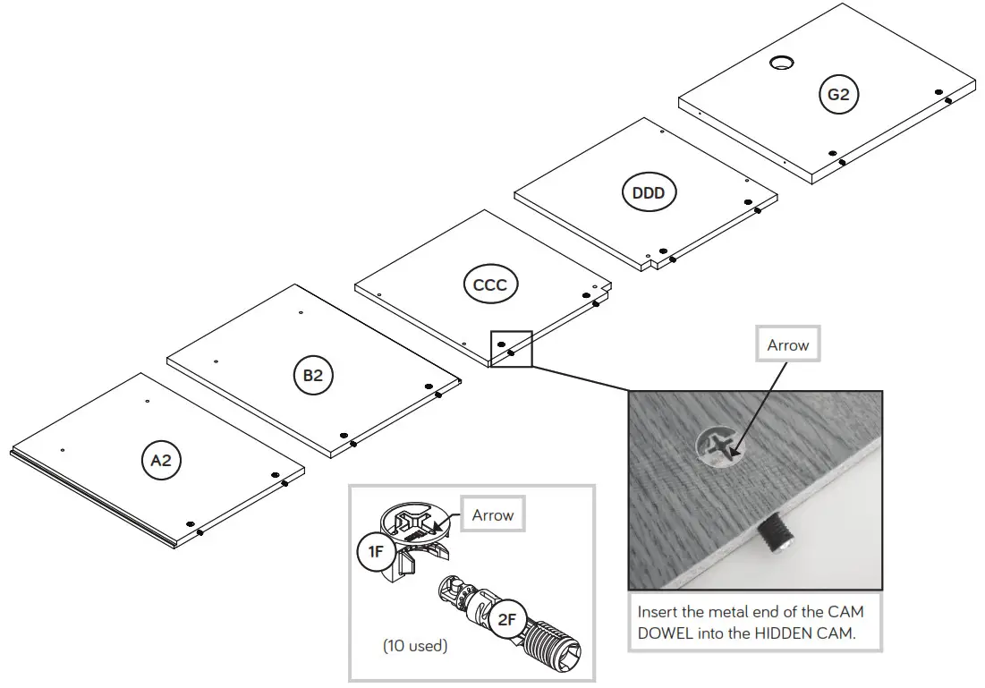
♦ Push ten HIDDEN CAMS (1F) into the ENDS (A2 and B2), UPRIGHTS (CCC and DDD), and CENTER BACK (G2). Then, insert the metal end of a CAM DOWEL (2F) into each HIDDEN CAM.
| Look for this icon. It means a video assembly tip is available at www.sauder.com/service/tips |
 |
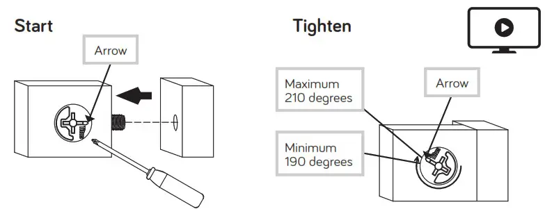
Do not tighten the HIDDEN CAMS in this step.
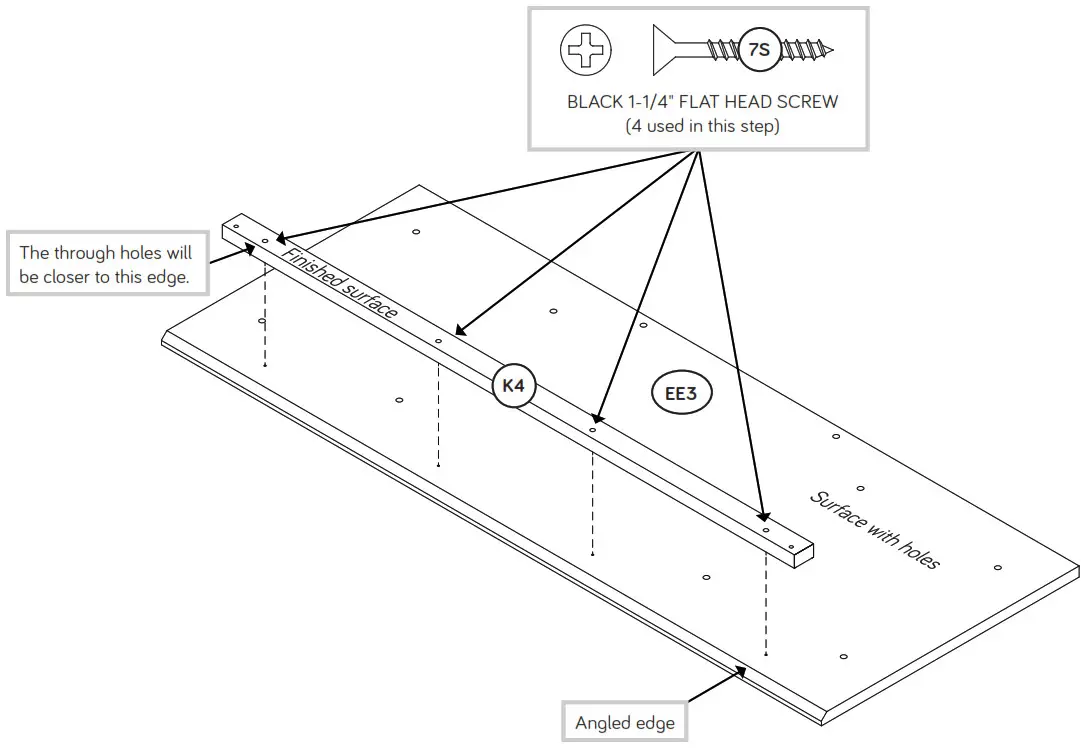
Step 2
♦Fasten the VALANCE (K4) to the TOP (EE3). Use four BLACK 1-1/4″ FLAT HEAD SCREWS (7S).
♦ NOTE: Do not overtighten the SCREWS.
 Some assembly (and snacks) required. Some assembly (and snacks) required. |
 Step 3
![]() Caution
Caution
Do not stand the unit upright without the BACK fastened. The unit may collapse.
![]()
Risk of damage or injury. HIDDEN CAMS must be completely tightened. HIDDEN CAMS that are not completely tightened may loosen, and parts may separate. To completely tighten:
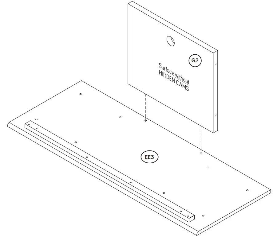
 Step 4
♦Fasten the UPRIGHTS (CCC and DDD) to the TOP (EE3).
♦Tighten four HIDDEN CAMS.
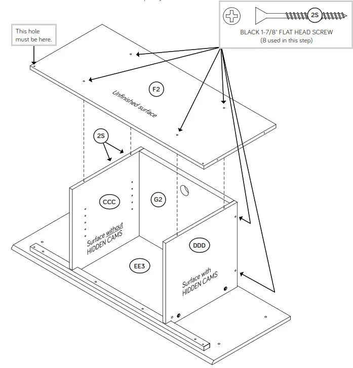
♦Fasten the UPRIGHTS (CCC and DDD) to the CENTER BACK (G2). Use four BLACK 1-7/8″ FLAT HEAD SCREWS (2
♦ Fasten the BOTTOM (F2) to the UPRIGHTS (CCC and DDDUse four BLACK 1-7/8″ FLAT HEAD SCREWS (2S).
♦ NOTE: Start each SCREW a few turns before completely tightening any of them.
 Step 5
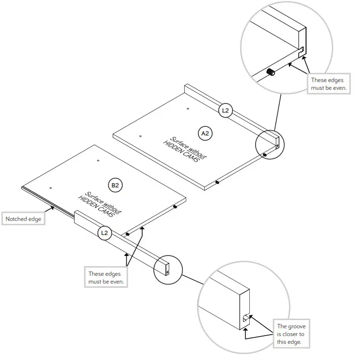
♦Slide the END MOLDINGS* (L2) onto the notched edges of the ENDS (A2 and B2).
♦NOTE: The MOLDINGS should be even with the edges of the ENDS.
♦*U.S. Patent No. 5,499,886
Step 6
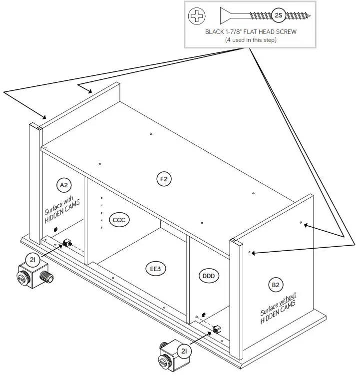
♦Fasten the ENDS (A2 and B2) to the TOP (EE3). Tighten four HIDDEN CAMS.
♦Fasten the ENDS (A2 and B2) to the BOTTOM (F2) Use four BLACK 1-7/8″ FLAT HEAD SCREWS (2S).
♦Push a MAGNETIC CATCH (2I) into the holes of each UPRIGHT (CCC and DDD) as shown.
 Step 7
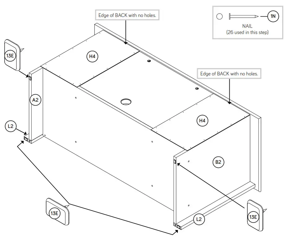
♦Carefully turn your unit onto its front edges. Lay the BACKS (H4) over your unit.
♦Make equal margins along the bottom and both side edges of the BACKS (H4). Push on opposite corners of your unit if needed to make it “square”.
♦Fasten the BACKS (H4) to your unit using the NAILS (1N).
♦With a hammer, tap four TACK GLIDES (13E) into the edges of the
ENDS (A2 and B2) and END MOLDINGS (L2).
 Caution
Do not stand the unit upright without the BACK fastened. The unit may collapse.
Step 8
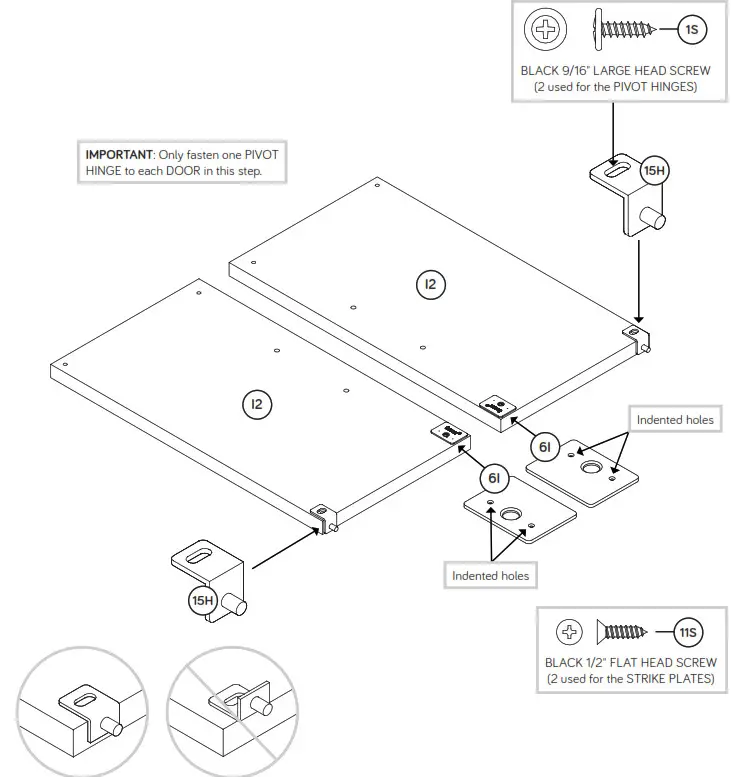
♦Fasten a PIVOT HINGE (15H) to each DOOR (I2). Use two BLACK 9/16″ LARGE HEAD SCREWS (1S).
♦Fasten a STRIKE PLATE (6I) to each DOOR (I2). Use two BLACK 1/2″ FLAT HEAD SCREWS (11S).
 Step 9
♦Carefully stand your unit upright.
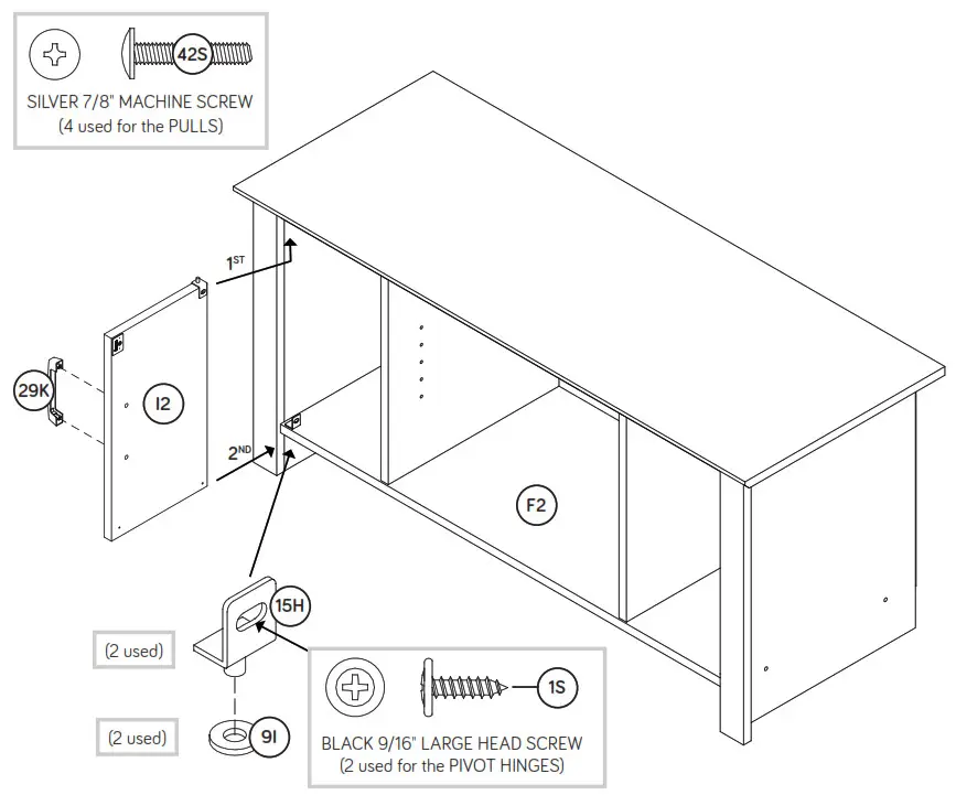
♦Insert a PIVOT HINGE (15H) into a WASHER (9I) and into the BOTTOM (F2).
♦Insert the PIVOT HINGE, which is fastened to the DOOR (I2), into the hole in the VALANCE. You will need to tilt your DOOR slightly.
♦Now, tip the DOOR in and fasten the free HINGE to the DOOR. Use a BLACK 9/16″ LARGE HEAD SCREW (1S).
♦Fasten a PULL (29K) to the DOOR (I2). Use two SILVER 7/8″ MACHINE SCREWS (42S).
♦NOTE: To make adjustments to the DOOR, loosen the SCREW in the HINGE, make needed adjustments and tighten the SCREW.
♦Repeat this step for the other DOOR (I2).
 Pro Tip: Lift with your legs. And, you know, your arms. Pro Tip: Lift with your legs. And, you know, your arms. |
Step 10
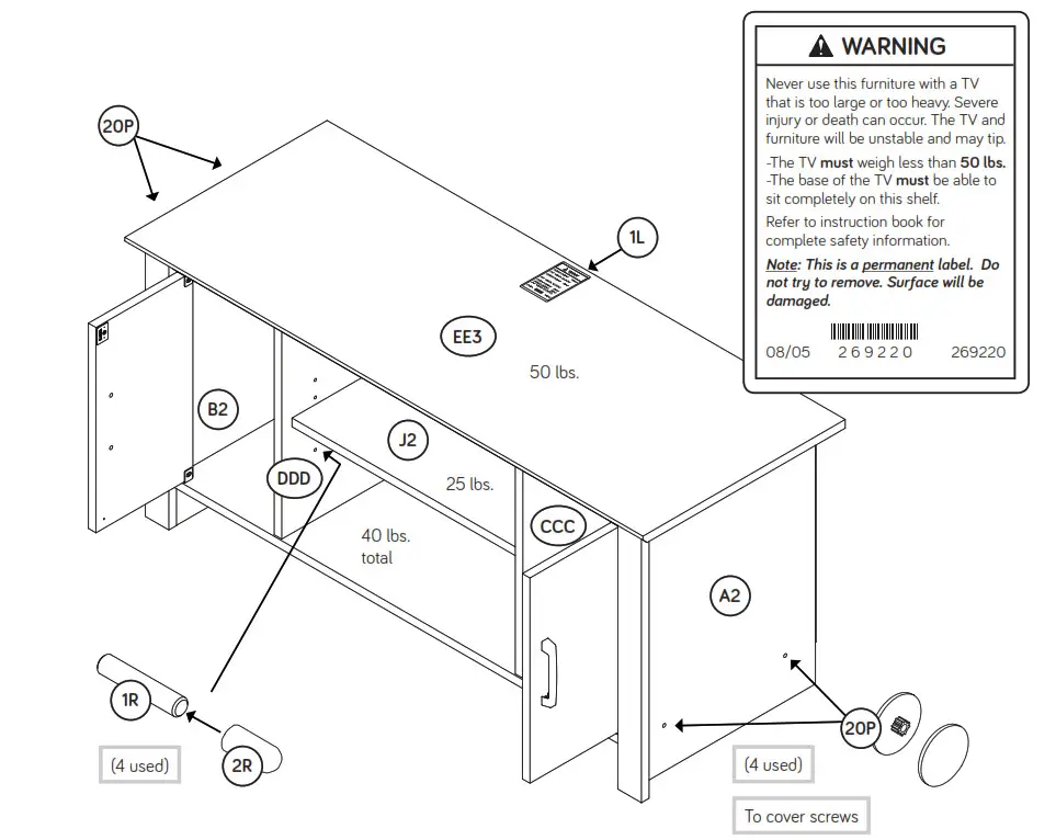
♦Push the RUBBER SLEEVES (2R) over the METAL PINS (1R). Insert the METAL PINS into the hole locations of your choice in the UPRIGHTS (CCC and DDD). Set the ADJUSTABLE SHELF (J2) onto the METAL PINS.
♦Center a SCREW COVER (20P) over the head of each SCREW and gently tap in with your hammer.
♦ Apply the WARNING LABEL (1L) to the TOP (EE3). You should be able to read the label when the TV is removed from the unit. When the TV is in place, it should hide the label. Peel off the backing and apply the label as shown in the diagram.
♦NOTE: This is a permanent label intended to last for the life of the product. Once applied, do not try to remove it.
♦NOTE: Please read the back page of the instruction booklet for important safety information.
♦This completes the assembly. Clean with a damp cloth. Wipe dry.
And to celebrate, why not share your success story at Walmart.com or
If you need assistance please contact customer service at 800-523-3987 Monday-Friday – 9 a.m. to 5:30 p.m. EST (except holidays) or at sauder.com/service.
√Register your new product online
For immediate service, 24 hours per day, 7 days per week, to order replacement parts, access assembly tips and register your product, visit www.sauder.com/service
So, how did it go?
Set a world record for speed?
Feeling good about yourself?
Nice. Get social with it on any of these quality share sites.
*****And don’t forget to rate and review your piece at Walmart.com in the product detail page.
General Conformity Certifi cate
- This certifi cate applies to the Sauder Woodworking Product identifi ed by this Instruction Book.
- This certifi cate applies to compliance of this product with the CPSC Ban on Lead-Containing Paint (16 CFR 1303).
- This product is manufactured by:
Sauder Woodworking Company
502 Middle St.
Archbold, OH 43502
419-446-2711 - Date of Manufacture: ________