
Installation Instructions
Tools


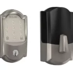
A. Key
B. Cylinder Cap
C. iButton Assembly
D. Deadbolt
E. Mounting Plate
F. 9v Battery
G. Mounting Screws (2)
H. Thumbturn Assembly
J. Screws (2)
K. Drive-in Faceplate
L. Square-corner Faceplate
M. Rounded-corner Faceplate
N. Deadbolt/Strike Screws (4)
P. Strike
Q. Reinforcement Screws (3)
R. Dust Box
S. UL Cup (BE367F ONLY)
T. UL Screw (BE367F ONLY)
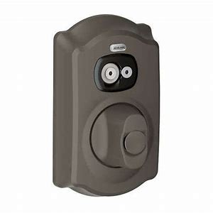
Install Lock
1 Template Is Included In Box
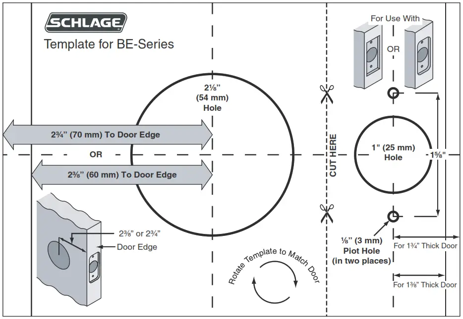
IMPORTANT: Template shown is not full size
2 Check Door Holes
Note: If holes do not match template, purchase a GuideRight® jig or visit www.schlage.com for door drilling instructions.
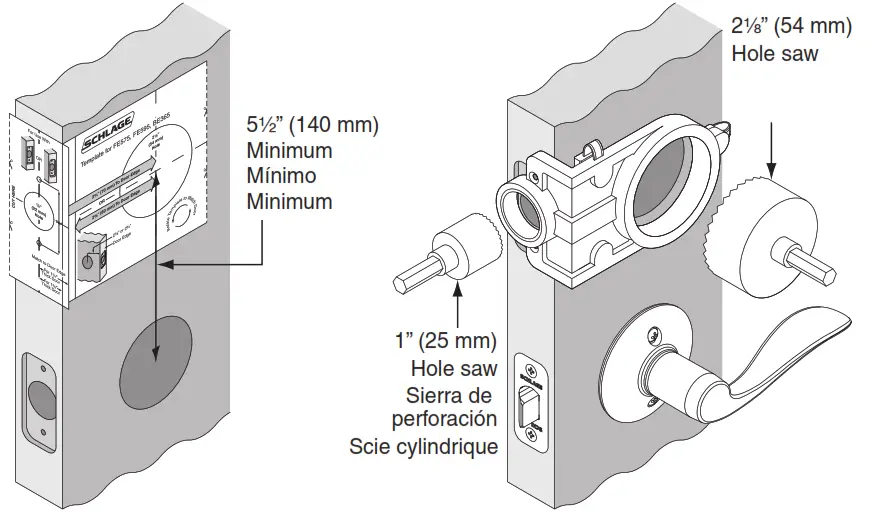
3 FOR BE367F ONLY: Measure and Drill Hole

4 FOR BE367F ONLY: Install UL Cup

5 If Needed, Adjust Deadbolt

6 Choose Deadbolt Faceplate
Match faceplate to your door.

7 Install Deadbolt

8 Install Keypad Assembly
IMPORTANT: Cable passes over top of deadbolt.

9 Install Inside Mounting Plate
IMPORTANT: Pull excess wire through mounting plate.

10 Check Cam and Install Screws
NOTE: Ensure lock is straight before tightening.

11 Install Battery and Connect Cables

12 Route and Tuck Cables

13 Install Thumbturn

14 Install Strike and Dust Box

Check Operation
If you have a yellow construction iButton Credential, then test lock operation
IMPORTANT: If the BE367 is unprogrammed, then all yellow construction iButtons will operate lock. Yellow Construction iButtons are disabled automatically when the BE367 is programmed.

For Programming, See the SMS/SMS Express Site Set-Up Guide
Questions? (888) 805-9837
![]()
© Allegion 2014
Printed in U.S.A.
P515-488 Rev. 11/14-online