Installation Manual

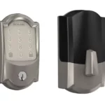
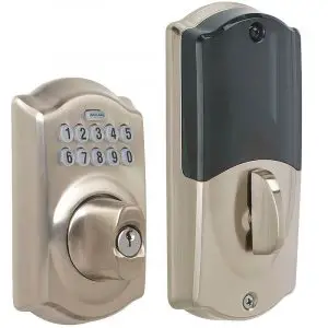
Home Keypad Lock BE369
1.Important Information
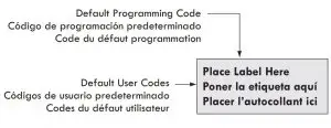
- Lock comes preset with a default Programming Code.
- Lock comes preset with two default User Codes
![]()
Need Help?

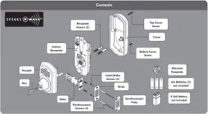
Tools Needed
- Phillips screwdriver
- Tape Measure
- Pencil
Optional
- Flathead Screwdriver
- Wood Block
- Hammer
![]()
2. Install deadbolt and strike.
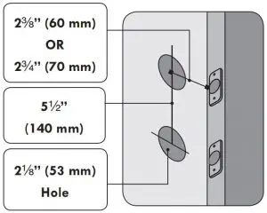
2a. Check dimensions.
If door dimensions do not match, go to www.nexiahome.com for drilling instructions.
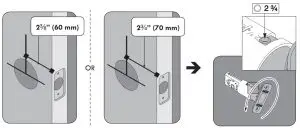
2b. Check backset.
This lock will fit either a 23/8 ” backset or a 23/4 ” backset. The bolt is preset to fit a 23/8” backset. If your backset is not 23/8”, you need to adjust your bolt by rotating it counterclockwise.
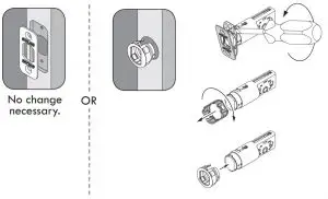
2c. If necessary, change bolt faceplate
Check edge of door to determine the type of faceplate required.
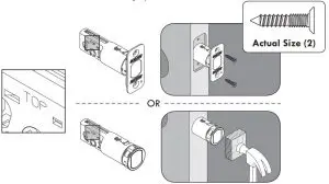
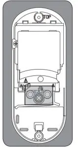
2d. Install bolt.
The word “TOP” should be facing upward.
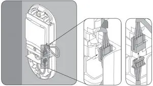
3. Align tailpiece of exterior keypad and interior baseplate.
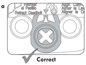
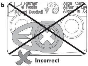
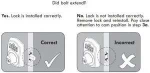
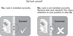
3a. Check the cam on the interior baseplate.
Locate the cam on the baseplate. This cam has a small arrow on it that should point to the arrow that is printed on the casing above the cam, like picture “a” below. If the cam is oriented sideways, like the picture “b”, rotate the cam until the arrows match.
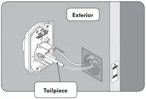
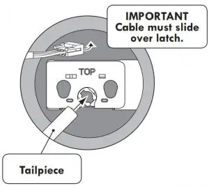
3b. Install exterior keypad.
Bar should slide smoothly through hole in latch. If not, check door dimensions. Feed the cable over the top of the bolt assembly then slide the tailpiece through the correct hole as shown below.
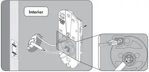
3c. Install the interior baseplate.
Feed the cable through the hole as shown below. DO NOT connect the cable at this time. Then slide the baseplate onto the tailpiece and press against the door. The baseplate should stay in place.
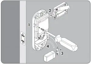
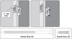
4. Secure interior baseplate and install batteries.
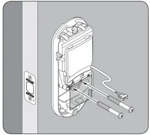
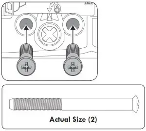
4a. Secure interior baseplate.
Use the two screws shown to secure the baseplate to the door.
4b. Connect cable.
Snap the connectors together. Tuck them into the open space in the baseplate. Make sure no wires will be pinched when the cover is installed.
4c. Install batteries.
- Unscrew battery holder.
- Slide out battery holder and install batteries.
- Attach 9 volt battery to battery connector.
- Place 9 volt battery in compartment.
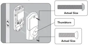
5. Install interior cover.
5a. Install cover.
Place the cover against the door and secure using the two screws. You may need to rotate the thumbturn to the proper position, shown below.
Tuck wires into open space on baseplate. Be careful not to pinch any wires between cover and baseplate.
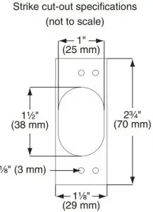
6. Install the strike.
6a. Prepare the frame for the strike.
Mark the 4 hole locations. Drill them as shown.
If the strike cut-out has not been prepared in the frame, see the specifications on the right
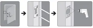
6b. Install the strike.
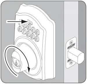
7. Test lock.
![]()
![]()
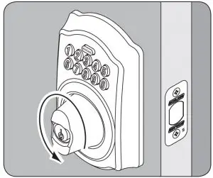
7a. Test locking function.
- Press

- Rotate thumbturn towards door edge until bolt extends.
7b. Test unlocking function.
-
- Find User Code A on the yellow sticker.
- Enter User Code A (four digits) into the keypad.
- Rotate thumbturn away from door edge until bolt retracts.
FCC STATEMENT
This device complies with part 15 of the FCC rules. Operation is subject to the following two conditions: (1) This device may not cause harmful interference, and (2) this device must accept any interference received, including interference that may cause undesired operation.
Changes or modifications to this equipment not expressly approved by Schlage could void the user’s authority to operate the equipment.
FCC ID: P2GBE369 IC: 7654A-BE369
![]()
© Allegion 2014
Printed in U.S.A.
P516-085 09/14-d