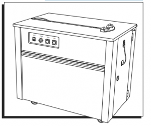

POLYPROPYLENE STRAPPING MACHINE
1-800-295-5510
uline.com
Para Español, vea páginas 4-6.
Pour le français, consulter les pages 7-9

TECHNICAL DATA
Strapping Speed: 2.5 Seconds/Strap
Dimensions (L x W x H): 35½ x 23 x 30½”
Net Weight: 220 lbs.
Max. Tension: 100 lbs.
Strap Width: 1/4″ – 5/8″
Core Capacity (Core Dia. x Width): 8 x 8″, 9 x 8″ or 11 x 8″
Safety Switch: Stops machine when top is lifted.
Power: 110 VAC, 50/60 Hz, Single phase.
MACHINE SETUP
Open lid and remove contents from tray. Install package guide on lid.
LOAD REEL

- Remove plastic reel from machine. It comes preset for 9″ core. Remove outer ring adapter for 8″ core. For 11″ strapping core, the H-959-TC075 adapter can be purchased. (See Figure 1)
- Load Strapping onto reel. DO NOT REMOVE BANDING UNTIL LOADED. Make sure strap is going in correct direction indicated by red arrow. (See Figure 1)
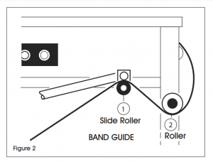
- Pull slide roller bar down and thread strapping over (1) and under (2). Thread strap through guide (Ref 10) until it reaches top of machine. (See Figure 2)

OPERATION INSTRUCTIONS
- Set strap feed length: Determine the length of strap needed. Set control for 0-6. Lengths listed in meters. 1 = 3 ft. of strap. Example: for 6 ft. of strapping, set the control at “2”. (See Figure 3)
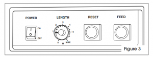
- Turn power ON. Allow machine to heat up 3-4 minutes. Strap won’t seal if heating blade is not hot enough. (See Figure 3)
- Pre-feed the strap: Press and hold the FEED button until the desired length of strap feeds out. (See Figure 3)
NOTE: Pre-feeding is only necessary after installing a new strap coil or finishing a coil. - Strapping the package:
a. Place package on the machine against the package guide. (See Figure 4)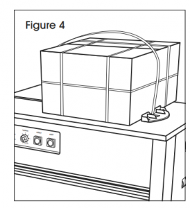
b. Pass strap around package and insert the strap end into the strap inlet to start the strapping tensioning and heat sealing cycle. (See Figure 5)
c. Strap tensions, heat seals and cuts. Remove package.
d. Timer resets, strap feeds out and machine is ready for the next package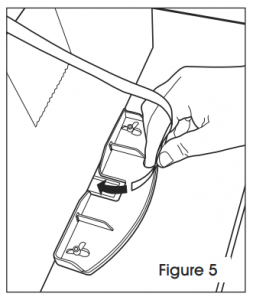
- Turn power OFF.


MOTOR TIMER
The timer is located on the printed circuit box (PCB Box). If your machine runs for a long time between packages, turn the timer down. If the machine is used more frequently, turn the timer up so the motor isn’t starting and stopping all the time. (See Figure 6) 
REFERENCE

| # | DESCRIPTION |
| 1 | POWER SWITCH: TURNS MACHINE ON/OFF. |
| 2 | FEEDING LENGTH CONTROL: LENGTHS LISTED IN METERS. |
| 3 | RESET BUTTON: COMPLETES CYCLE AND RETURNS MACHINE TO “HOME” POSITION. |
| 4 | STRAP FEED BUTTON: RUNS OFF ANY LENGTH OF STRAP. |
| 5 | PLUG: 110V |
| 6 | STRAP REEL: HOLDS STRAP COIL. |
| 7 | BRAKE: STOPS BAND REEL FROM OVER ROTATING. |
| 8 | STRAP GUIDE FOR BRAKE: STRAP THREADS THROUGH GUIDE. |
| 9 | STRAP BYPASS GUIDE: STRAP THREADS THROUGH GUIDE. |
| 10 | FEED GUIDE |
| 11 | STRAP INSERTION INLET: DETECTS LEADING EDGE OF STRAP TO START TENSIONING/HEAT SEALING CYCLE. |
ADJUSTMENTS
STRAP WIDTH
Make adjustments at the Strap Outlet and the Strap Inlet.
- Machine comes preset for 1/2″ strapping.
- Strap Inlet: Loosen two black screws with Allen wrench. Set the Strap Inlet guide about 1/16″ wider than the strapping you are using and align with the Strap Outlet. Retighten socket screws. (See Figure 7)
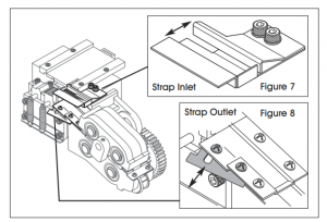
- Strap Outlet: Loosen two Phillips head screws. (See shaded areas in Figure 8) Adjust the width to accept width of strap you are using. Set the strap outlet guide at 1/2″ for 1/4″ and 3/8″ strapping and 5/8″ for 1/2″ strapping. Retighten screws. (See Figure 8)

TENSION ADJUSTMENT
- The strap tension adjustment handle is located at the back of the machine. (See Figure 9)
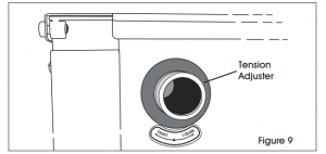
- Machine comes preset at 0 tension. Recommend starting at middle point of tension gauge bar.
- Turn the handle clockwise to increase tension; counterclockwise to decrease tension.

MAINTENANCE
CLEANING
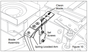
After use, clean residue from top and bottom of heater blade with Scotch-Brite™ Pad (S-11724). Brush until metal is bright.
- Remove heater cover. To remove blade, pull back on spring-loaded arm. (See Figure 10)

Use Air Gun or ULINE Air In A Can to clean parts of plastic residue. (See Figure 11)
1-800-295-5510
uline.com