YAMAHA Integrated Amplifier Owner's Manual
Thank you and congratulations on your purchase of this Yamaha product. · You can enjoy the high-quality stereo sound of this integrated amplifier at home. · To use the product properly and safely, we suggest that you read this manual and the “Safety Brochure” thoroughly.
Keep the manual in a safe, accessible place for future reference.
Features
◆ Floating balanced circuit for power amplifier
◆ Fully-balanced transmission from input to output
◆ Tone control circuit with a parallel volume system
◆ Large power supply with four separate circuits
◆ Left-right symmetrical design
◆ Fully discrete phono amp
◆ Low-impedance, high-performance headphone amp
Things to know before using this product
About this manual
- This manual describes the unit’s features and connection procedures.
- The illustrations as shown in this manual are for instructional purposes only.
- Specifications and appearance are subject to change without notice.
 WARNING” describes precautions to be followed to avoid the possibility of serious injury or even death.
- CAUTION” describes precautions to be followed to avoid injury.
- “NOTICE” describes precautions to be followed to avoid malfunction or damage to the product.
- ” Note ” describes supplemental information about the product.
Supplied accessories
Please make sure that the following accessories are included in the package.
- Remote control
- Batteries (AAA, R03, UM-4) (×2)
- Power cable*
- Owner’s Manual (this book)
- Safety Brochure
* Multiple power cables might be included in the package depending on the area of distribution. Please use the one that is appropriate for your AC outlet.
Part Names and Functions
This section lists the names and describes the function of various parts on the front and rear panels, and the remote control.
Front panel
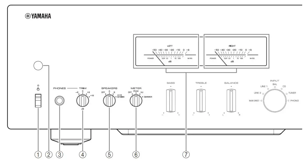
(1)  (Power) switch/indicator
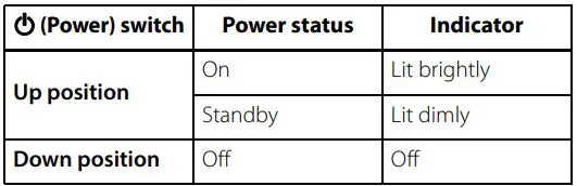
While the (Power) switch is in the up position, press the AMP key on the remote control repeatedly to switch the power to the unit between on and standby mode. In addition, under either of the following conditions, the unit will enter standby mode.
- If the Auto Power Standby function is enabled. (→ page 10)
- If you turn off the power to a device that has been set to trigger connection to this unit. (→ page 20)
NOTICE
If you plan not to use the unit for an extended period of time, be sure to unplug the power plug from the AC outlet. Even when the power is turned off, a minimal amount of electric current is still flowing to the unit.
Note
- After you turn on the unit, it will take a few seconds before the unit can reproduce sound.
- Do not turn on the power to this unit again within 10 seconds after the power has been turned off. Doing so may generate noise.
- While the unit is in standby mode, to turn on power to the unit first set the (Power) switch to the down position to turn the power off, then set the switch to the up position.
- While the unit is in standby mode, if you unplug the power cable from the AC outlet and then plug it in again, the power to the unit will be turned on.
 (2) Remote control sensor
Receives signals from the remote control. (→ page 14)
(3) PHONES jack
Connect your headphones here.
Note
- Connecting the headphones here will result in the following:
– No sound will be heard from the connected speakers.
– Audio signals will not be output at the PRE OUT jacks.
– You will be unable to select MAIN DIRECT as the input source. - If MAIN DIRECT is selected as the input source, audio signals will not be output at the PHONES jack.
(4) TRIM selector
Switches the headphone amp gain. Select the gain setting that is appropriate for your headphones.
Available gain: -6 dB, 0 dB, +6 dB, +12 dB
(5) SPEAKERS selector
Switches sets of speakers connected to the SPEAKERS L/R CH A and B terminals on the rear panel as follows:
OFF: No audio signals will be output from the speakers.
A: Audio signals will be output from the set of speakers connected to the A terminals.
B: Audio signals will be output from the set of speakers connected to the B terminals.
A+B BI-WIRING: Audio signals will be output from the sets of speakers connected to the A and B terminals. Select this position when you plan to make a bi-wired connection. ( →page 19)
NOTICE
[Model for Asia] If you connect two sets of speakers (A+B), use the speakers with an impedance of 12 or higher.
[Other models] If you connect two sets of speakers (A+B), use the speakers with an impedance of 8 or higher.
(6) METER selector
Switches the meter function as follows:
OFF: Turns off meter operation and display illumination.
PEAK: Switches the meter display type to a peak level meter. The peak level meter shows the highest instantaneous level of an audio output signal.
VU: Switches the meter display type to a VU (Volume Unit) level meter. The VU level meter shows an effective audio output value that represents the way sound is perceived by human ears.
DIMMER: When selected, the DIMMER automatically changes the brightness of the meter display in steps. When you see the brightness level you desire, switch to another setting parameter to lock in the new brightness setting.
(7) Meter (LEFT/RIGHT)
Indicates the audio output level of the left (LEFT) and right (RIGHT) channels.
Front Panel
(8) BASS control
Adjusts the volume level of the bass range.
Adjustable range: -10 dB 0 +10 dB
(9) TREBLE control
Adjusts the volume level of the treble range.
Adjustable range: -10 dB 0 +10 dB
(10) BALANCE control
Adjusts the audio output balance between the left and right speakers to compensate for sound imbalances caused by speaker locations or listening room conditions.
Note
- If both BASS and TREBLE controls are set to 0 (zero), the audio signal will bypass the tone control circuit.
- The BASS, TREBLE, and BALANCE control settings will not affect the input signals at the MAIN IN jacks nor the output signals at the LINE 2 OUT jacks.
(11) INPUT selector/indicator
Selects the input source. The indicator for the selected input source lights up. Audio signals of the selected input source will be output at the LINE 2 OUT jacks.
MAIN DIRECT: Selects the component connected to the MAIN IN jacks as the input source.
LINE 1/LINE 2: Selects the component connected to the LINE 1 or LINE 2 jacks as the input source.
BAL: Selects the component connected to the BAL input jacks as the input source.
CD: Selects the CD player connected to the CD input jacks as the input source.
TUNER: Selects the tuner connected to the TUNER input jacks as the input source.
PHONO: Selects the turntable connected to the PHONO input jacks as the input source.
Note
- If MAIN DIRECT is selected as the input source, audio signals will not be output at the PRE OUT, LINE 2 OUT or PHONES jacks.
- If LINE 2 is selected, audio signals will not be output at the LINE 2 OUT jacks.
(12) PHONO switch
Set this switch to the MM or MC position according to the type of magnetic cartridge of the turntable connected to the PHONO input jacks on the rear panel.
Note
Before you replace the cartridge for the turntable, be sure to turn off the power to this unit.
(13) Feet
If the unit is unstable, adjust the height of the feet as needed by rotating them.
(14) AUDIO MUTE switch/indicator
Press this switch to reduce the current volume level by approximately 20 dB. The indicator will light up. Press again to restore the audio output to the previous volume level. The indicator will turn off.
(15) VOLUME knob
Adjusts the volume level. This setting will not affect the output level at the LINE 2 OUT jacks.
NOTICE
If you select MAIN DIRECT as the input source for this unit, the volume level will be fixed. In this case, to adjust the volume level, use the volume control on the external amplifier connected to the MAIN IN jacks.
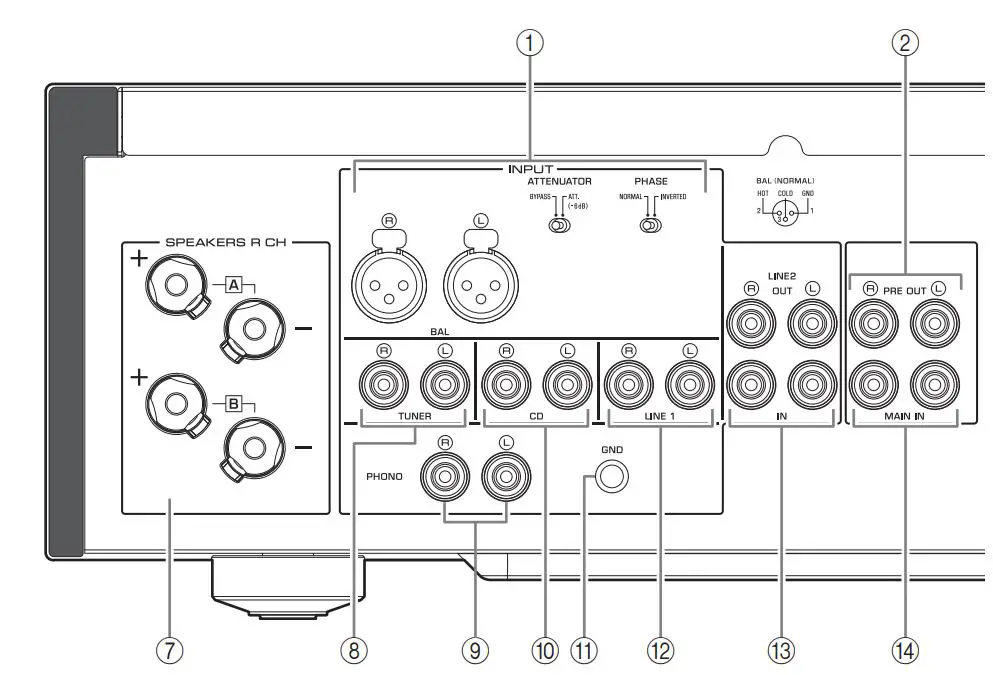
Rear panel

(1) BAL (balanced) input jacks
Note
Set the ATTENUATOR selector and PHASE selector appropriately for the playback component that is connected to these jacks. ( page 20)
(2) PRE OUT jacks
Note
- Audio signals output at the PRE OUT jacks are the same channel signals that are output at the SPEAKERS L/R CH terminals.
- The following parameter settings are effective for audio signals output at the PRE OUT jacks.
– BASS
– TREBLE
– BALANCE
– VOLUME
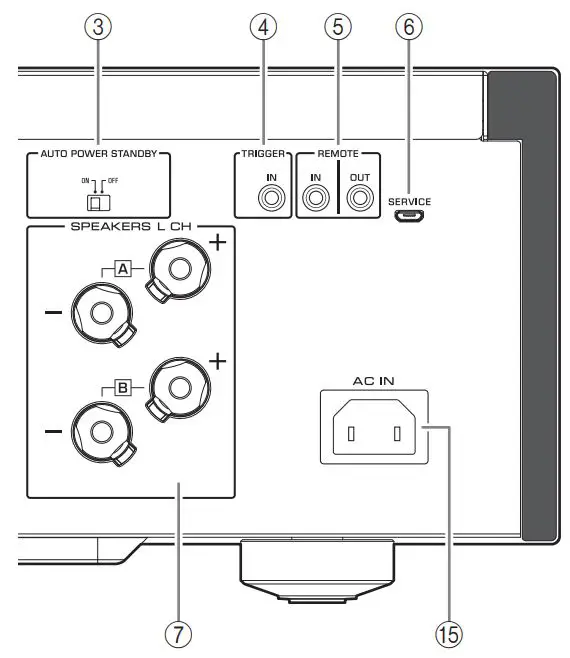
(3) AUTO POWER STANDBY switch
ON: The unit enters standby mode automatically if it is left turned on and not operated for eight hours (Auto Power Standby function).
OFF: The unit does not enter standby mode automatically.
(4) TRIGGER IN jack
Connect external components that support the trigger function. ( →page 20)
(5) REMOTE IN/OUT jacks
Connect external components that support the remote function. ( →page 21)
(6) SERVICE jack
This jack is used to test the product.
(7) SPEAKERS L/R CH terminals
(8) TUNER input jacks

(9) PHONO input jacks
(10) CD input jacks
(11) GND (Ground) terminal
If you connect your turntable to this unit, ground it to the GND terminal. Doing so may reduce noise.
![]() CAUTION
CAUTION
Do not loosen the GND terminal knob excessively. Otherwise, the knob may come off and a child may swallow it accidentally.
Note
This is not a safety ground.
(12) LINE 1 input jacks
(13) LINE 2 jacks
Connect external components that feature analog audio in/out jacks.
(14) MAIN IN jacks
Connect external components that feature a volume control function so that you can use this unit as a power amplifier.
NOTICE
If you select MAIN DIRECT as the input source for this unit, the volume level will be fixed. In this case, to adjust the volume level, use the volume control on the external amplifier connected to the MAIN IN jacks.
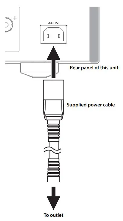
(15) AC IN jack
Connect the supplied power cable here. (→ page 22)
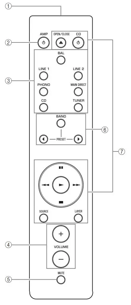
Remote control
(1) Infrared signal transmitter
Outputs infrared control signals toward the unit. (→ page 14)
(2)  AMP key
Turns on the power to the unit or switches it to standby mode. (→ page 6)
(3) Input select keys
Select the input source. Audio signals of the selected input source will be output at the LINE 2 OUT jacks.
BAL: Selects the component connected to the BAL input jacks as the input source.
LINE 1/LINE 2: Selects the component connected to the LINE 1 or LINE 2 jacks as the input source.
PHONO: Selects the turntable connected to the PHONO input jacks as the input source.
MAIN DIRECT: Selects the component connected to the MAIN IN jacks as the input source.
CD: Selects the CD player connected to the CD input jacks as the input source.
TUNER: Selects the tuner connected to the TUNER input jacks as the input source.
Note
- If MAIN DIRECT is selected as the input source, audio signals will not be output at the PRE OUT, LINE 2 OUT or PHONES jacks.
- If LINE 2 is selected, audio signals will not be output at the LINE 2 OUT jacks.
(4) VOLUME +/- keys
Adjust the volume level. This setting will not affect the output level at the LINE 2 OUT jacks.
NOTICE
If you select MAIN DIRECT as the input source for this unit, the volume level will be fixed. In this case, to adjust the volume level, use the volume control on the external amplifier connected to the MAIN IN jacks.
(5) MUTE key
Press this key to reduce the current volume level by approximately 20 dB. Press the key again to restore the previous volume level.
(6) Tuner control keys
Control the functions of a connected Yamaha tuner. For more information, refer to the owner’s manual for your tuner.
(7) CD player control keys
Control the functions of a connected Yamaha CD player. For more information, refer to the owner’s manual for your CD player.
⩠ OPEN/CLOSE key: Opens or closes the disc tray of a connected CD player. CD key: Turns on the power to a connected CD player, or switches it to standby mode.
►(Play): Starts playback of the CD player.
 (Pause): Pauses playback of the CD player. Press ►or to resume playback. ■ (Stop): Stops playback of the CD player.
 (Skip): Skips to the next track, or returns to the beginning of the current track.
SOURCE key: Selects the source to be played on the CD player. The playback source changes each time this key is pressed.
LAYER key: Toggles the playback layer of a hybrid super audio CD between “Super audio CD” and “CD.”
Note
Some Yamaha tuners or CD players might not support the tuner or CD player control keys.
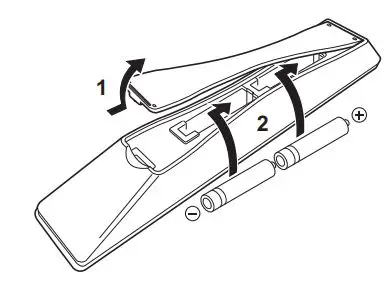
■ Installing batteries in the remote control
1 Remove the battery compartment cover.
2 Insert two batteries (AAA, R03, UM-4)
according to the polarity markings (+ and -) on the inside of the battery compartment.
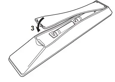
3 Reinstall the battery compartment cover.
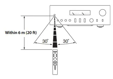
■ Operating the remote control
Operate the remote control in the range shown below by pointing it toward the remote control sensor on the front panel of the unit.
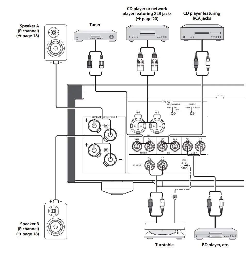
Connections
This section explains how to connect the unit to speakers and audio source components.
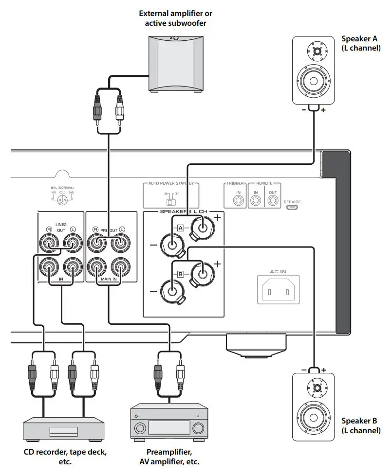
Connection diagram
![]() CAUTION
CAUTION
Be sure to complete all connections before plugging in the power cable to an AC outlet. ( → page 22)
NOTICE
If a component is connected to the MAIN IN jacks, the unit’s volume level will be fixed. Therefore, do not connect a CD player or other components that do not feature volume adjustment to the MAIN IN jacks. Otherwise, a loud sound may be emitted, resulting in malfunction of the unit or damage to the speakers.
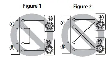
Note
- Because this power amplifier is of the floating balanced type, the following connections are not possible. – Connecting between two “+” (or two “-“) terminals of the left and right channels (Fig. 1).
– Connecting each “-” terminal of the unit’s left and right channels to the opposite channel speakers (cross connection, Fig. 2).
– Connecting the left/right channel “-” terminals (or accidentally allowing them to come in contact) with the metal part of the rear panel of this unit.
- Do not connect an active subwoofer to the SPEAKERS L/R CH terminals. Connect the subwoofer to the unit’s PRE OUT jacks.
Connecting speakers
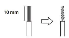
■ Using speaker cables
1 Remove approximately 10 mm of insulation
from the end of each speaker cable, and twist the exposed wires together tightly to prevent short circuits.
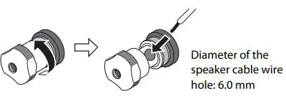
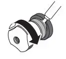
2 Unscrew the knob on each speaker terminal, and then insert the bare wire into the side hole on the terminal.
3 Tighten the knob.
![]() CAUTION
CAUTION
- Do not loosen the knob excessively. Otherwise, the knob may come off and a child may swallow it accidentally.
- To reduce the risk of electric shock, do not touch the speaker terminals while the power to the unit on.
NOTICE
- If the SPEAKERS terminals come into contact with a metallic rack, a short circuit may occur, resulting in damage to this unit. When installing the unit in a rack, maintain a sufficient clearance to prevent the SPEAKERS terminals from coming into contact with the rack.
- Do not let the bare speaker wires touch each other, nor let them touch any metal part of this unit. Otherwise, the unit and/or the speakers may be damaged.
Note
All connections must be correct: L (left) to L, R (right) to R, “+” to “+”, and “-” to “-“. For information regarding the connection procedure, refer to the owner’s manual for your speakers.
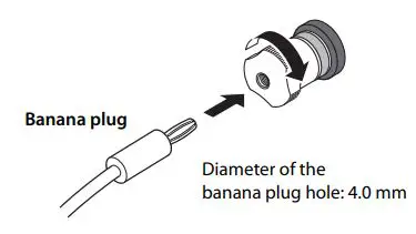
■ Using banana plug cables
(Models for U.S.A., Canada, Australia, China, and Taiwan)
First tighten the knob on the SPEAKERS terminal, and then insert the banana plug into the head of the knob.
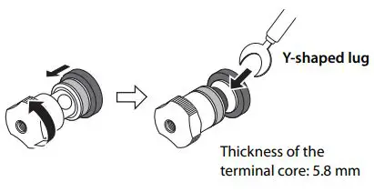
■ Using Y-shaped lug cables
1 Unscrew the knob, and then sandwich the Y-shaped lug between the ring part and base of the terminal.
2 Tighten the knob.
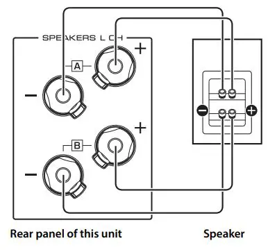
Bi-wired connection
A bi-wired connection separates the woofer from the mid and high ranges. Speakers that support bi-wired connection feature two pairs of terminals (total four terminals). These two pairs of terminals can divide the speakers into two independent parts. To make this kind of connection, you need to connect mid and high range drivers to one pair of terminals, and low range drivers to the other pair of terminals.
1 Remove the shorting bars or bridges on the speakers.
2 Connect this unit to the speakers as shown in the figure below.
An example of left channel connection
3 Set the SPEAKERS selector on the front panel to A+B BI-WIRING.
Balanced connection
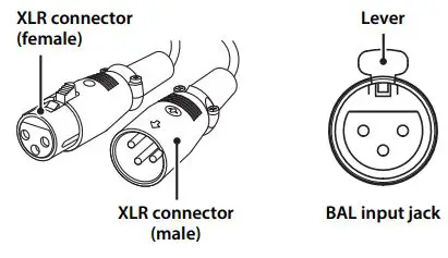
You can connect a CD player or network player that features XLR-type balanced output jacks to the BAL input jacks of this unit. Use XLR-type balanced cables for this connection.
ATTENUATOR selector: Enables you to set the allowable input level at the balanced input jacks. Select ATT. (-6 dB) if the audio output from the connected component sounds distorted.
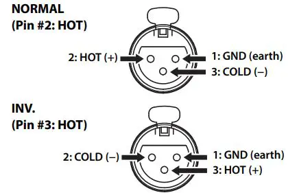
PHASE selector: Enables you to set the position (phase) of the HOT pin (pin #2: HOT or pin #3: HOT) at the balanced input jacks.
Refer to the instruction manual for the connected component to find out the position of the HOT pin at the balanced output jacks on the component.
Note
- Select NORMAL (pin #2 is HOT) for a Yamaha player.
- Do not use balanced and unbalanced connections for one component simultaneously. Doing so would create a ground loop that could generate static and noise.
- When connecting a cable, be sure to align the pins on the connector with the holes on the jack, and then insert the male XLR connector into the jack until you hear a click. To remove the cable, while pressing and holding down the lever on the BAL input jack, pull out the male XLR connector from the jack.
* For a balanced connection, select BAL as the input source.
Trigger connection
You can connect a Yamaha AV receiver or other component that supports the Trigger function. You can control this unit in sync with a connected component.
 When the power to the connected component is turned on, the power to this unit is also turned on. Simultaneously, the input source to the unit is set to MAIN DIRECT. If MAIN DIRECT has been selected as the input source for this unit, when the power to the connected component is turned off, this unit will enter standby mode.
Note
When the power switch on this unit is turned Off, the power to the unit will not be triggered.
Remote connection
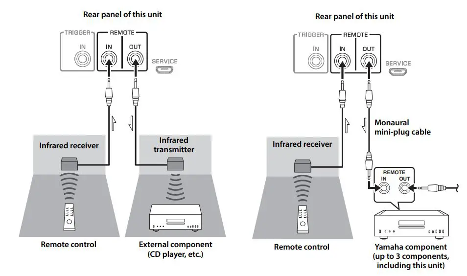
■ Operating the unit from another room
If you connect a commercially-available infrared receiver and transmitter to the unit’s REMOTE IN/OUT jacks, you will be able to operate the unit and/or external component from another room, using the supplied remote control.
■ Remote connection between Yamaha components
If you have another Yamaha component that supports remote connections, an infrared transmitter is not necessary. Connect an infrared receiver to the unit’s REMOTE IN/OUT jacks, as shown below. Up to 3 Yamaha components (including this unit) can be set up for remote connection.
Connecting the power cable
After all connections are complete, plug the power cable into the AC IN connector of the unit, and then plug the power plug into the AC outlet.
Appendix
This section lists technical specifications for this unit.
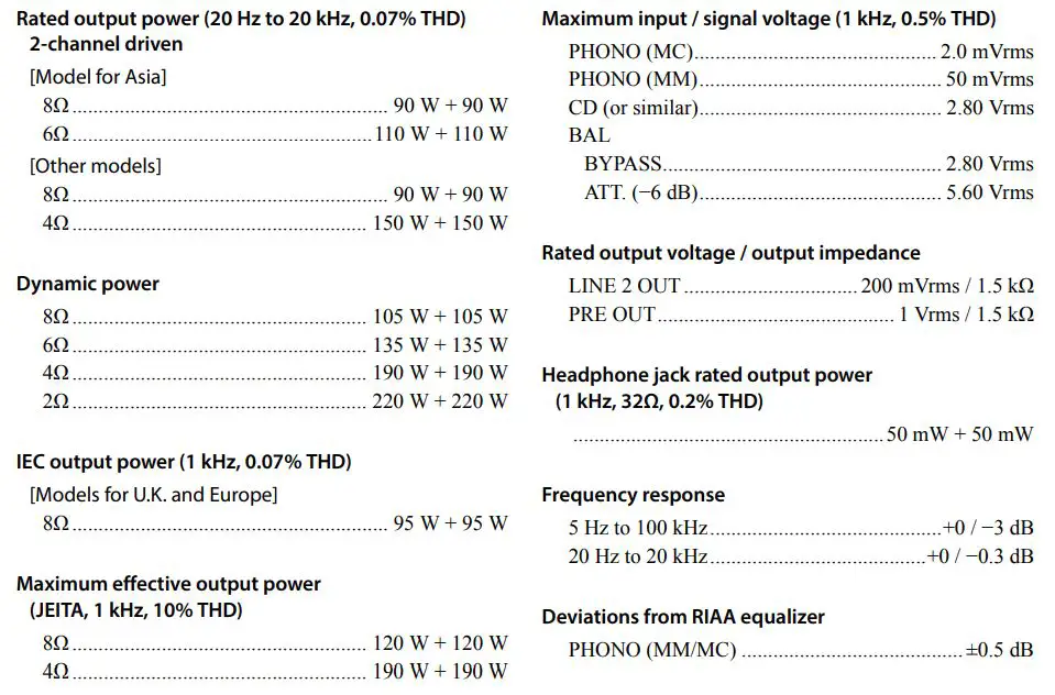
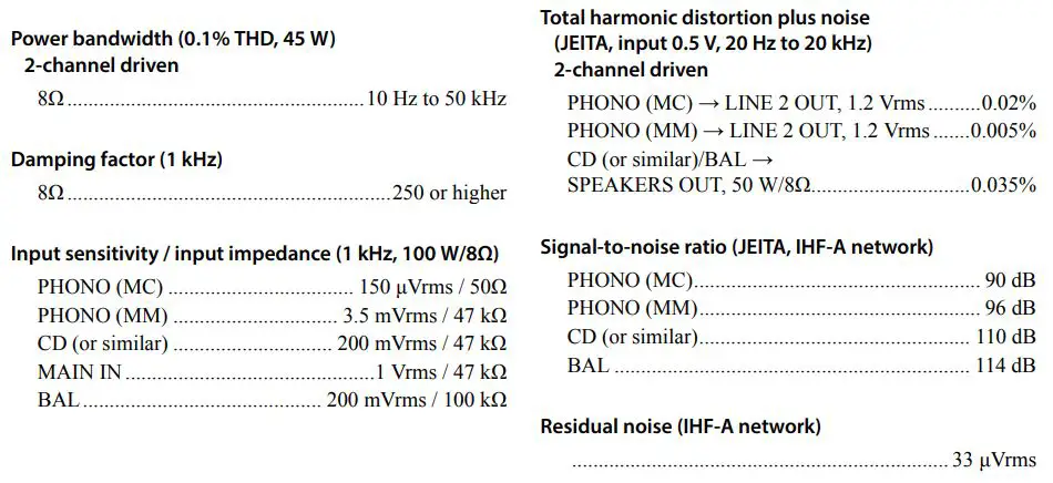
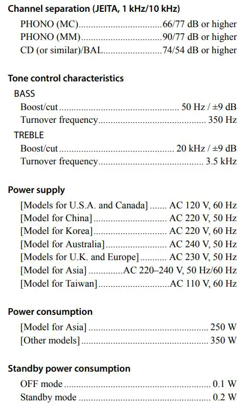
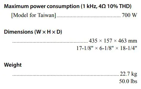
Specifications
 * The contents of this manual apply to the latest specifications as of the publishing date. To obtain the latest manual, access the Yamaha website and download the manual file.
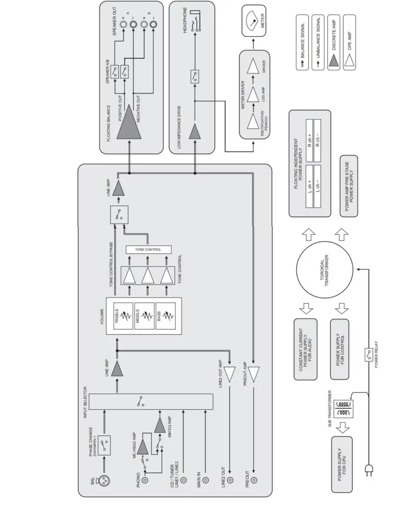
Block diagram

Acoustic characteristics
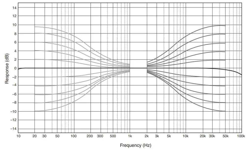
■ Tone control characteristics
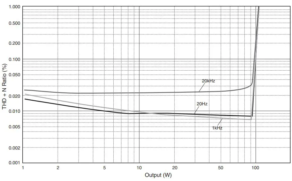
■ Total harmonic distortion
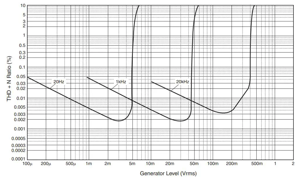
■ Total harmonic distortion (PHONO)

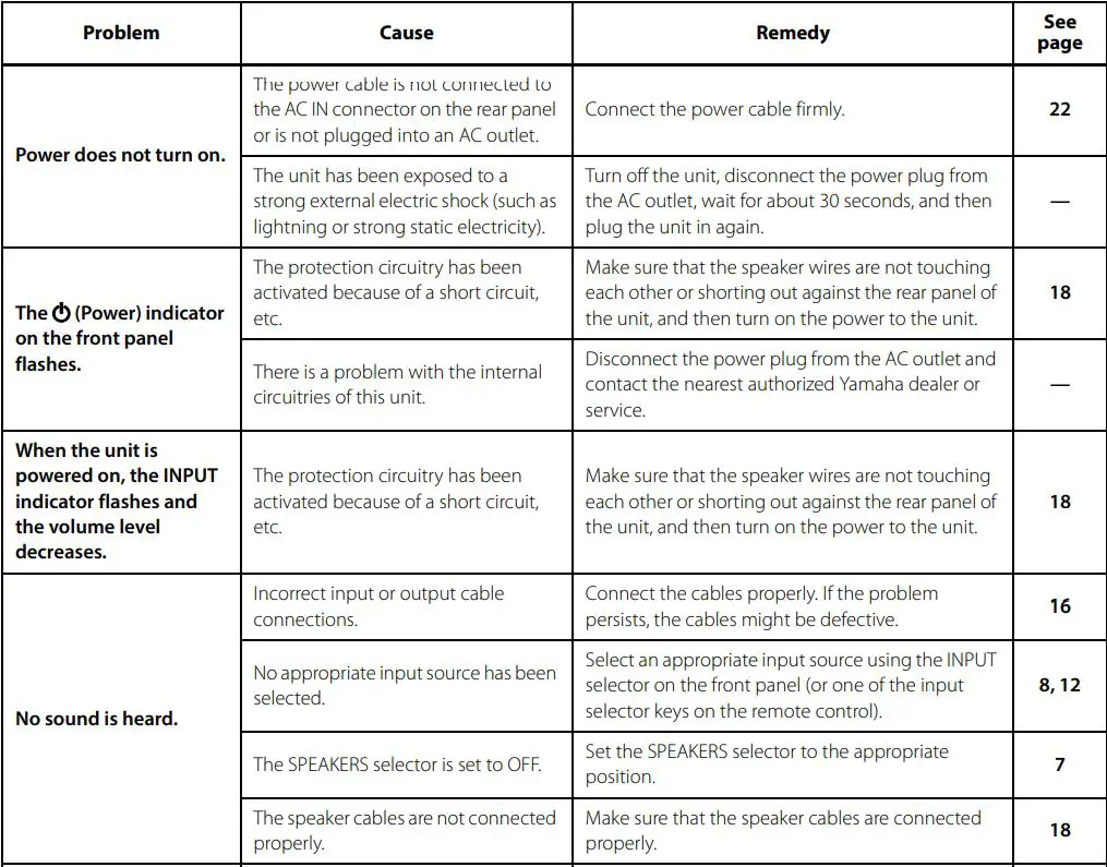
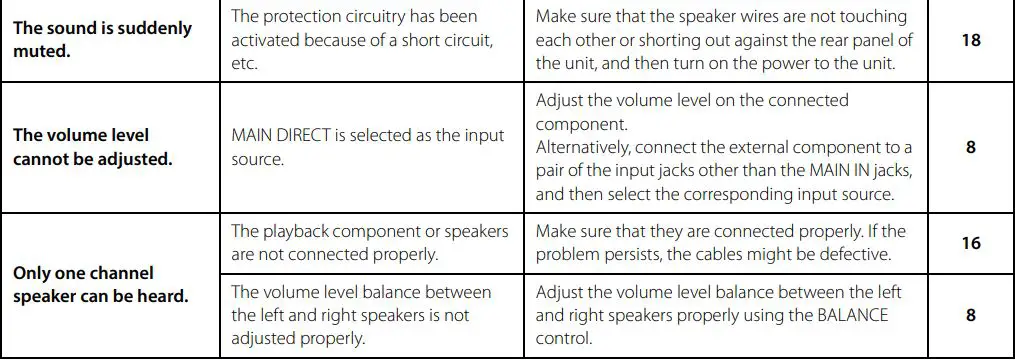
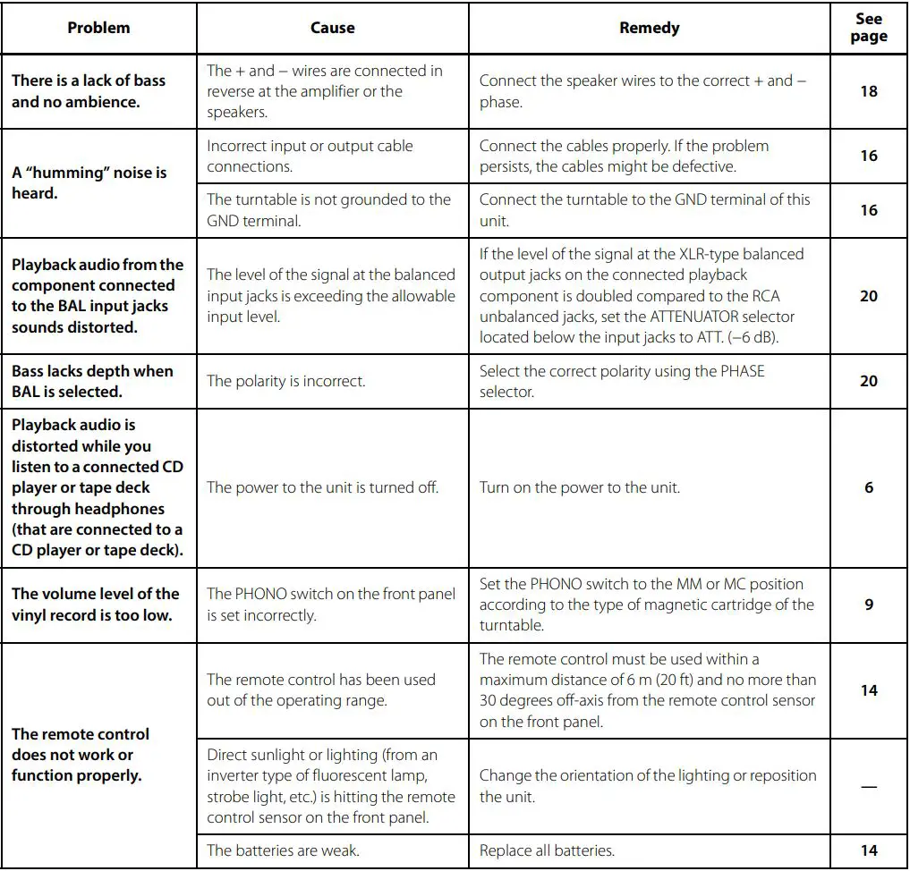
Troubleshooting
Refer to the table below if this unit does not function properly. If the instructions below do not help, or if the problem you are experiencing is not listed below, turn off the unit, disconnect the power plug, and contact the nearest authorized Yamaha dealer or service center.


Maintenance
Mirror-finish side panels
We recommend that you use a cleaning cloth such as those made for pianos.
Other surfaces
Do not use chemical agents, such as benzene or thinner for cleaning. Otherwise, the surfaces might be damaged. Wipe the surfaces using a soft dry cloth.
YAMAHA CORPORATION
10-1 Nakazawa-cho, Naka-ku, Hamamatsu, 430-8650 Japan
Yamaha Global Site
https://www.yamaha.com/
Yamaha Downloads
https://download.yamaha.com/
Manual Development Group
© 2020 Yamaha Corporation
Published 01/2020
IPEM-A0
UL VCV3030