YAMAHA DTX Electronic Drum Kit Assembly Manual
DTX6K3-X DTX6K2-X
Thank you for purchasing the Yamaha ELECTRONIC DRUM KIT DTX6K3-X or DTX6K2-X. This electronic drum kit can be used in your home or a studio, or onstage for live performances. For proper assembly and safe use, please read this assembly manual carefully before using it. After you have read the manual, keep it in a safe and handy place for future reference.
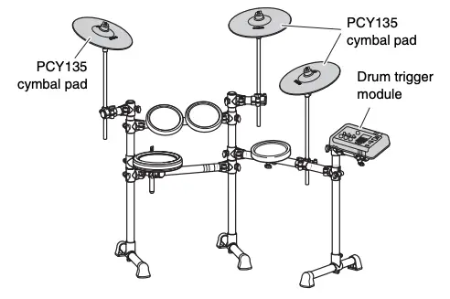
This manual describes the standard assembly procedure for the DTX6K3-X/DTX6K2-X electronic drum kits. It covers assembly, wiring and setting up the drum trigger module of the kit as shown below.
The illustrations show the DTX6K3-X electronic drum kit, but the information applies to the DTX6K2-X (except where indicated).

IMPORTANT
This manual describes the process of assembling a pad set and drum trigger module to an already assembled RS6 Electronic Drum Rack. Before starting the steps below, therefore, be sure to assemble your RS6 as described in the Owner’s Manual that came with it.
NOTICE
Lay a drum mat (sold separately) on the floor underneath the hi-hat stand and the kick pad. Alternatively, you can place cardboard from the drum kit packaging or the like on the floor to prevent it from being scratched.
PRECAUTIONS
Please read carefully before proceeding
The purpose of the precautions detailed below is to ensure that this electronic drum kit can be used safely without fear of injury or property damage. As a means of indicating the severity and immediacy of any risk of injury or property damage resulting from incorrect operation, these precautions are classified as either WARNING or CAUTION. The instructions displayed together with these precautions are extremely important in terms of ensuring safety, and therefore, they should be fully observed.
* After reading this Assembly Manual, ensure that it is kept in a safe, convenient location for future reference.
* Be sure to also read the Assembly Manuals and/or Owner’s Manuals that came with your pads and rack.
 WARNING
Failure to observe the precautions described below can result in serious injury or even death.
- Young children using this electronic drum kit should be supervised by a guardian to eliminate any possibility of injury.
- Holders for cymbal and tom pads have sharp tips. In order to avoid injury, therefore, you should take special care whenever handling these components.
- The anti-slip stoppers on kick pads and foot pedals have sharp tips. In order to avoid injury, therefore, you should take special care whenever handling these components.
- Be sure to securely tighten nuts and other fasteners when setting up this electronic drum kit. In addition, be sure to proceed slowly when loosening nuts. If this precaution is not observed, pads may fall off or the rack may collapse or fall over, possibly causing injury.
- Do not setup this electronic drum kit on a slope, on an unstable platform, or on any other unsafe surface. If this precaution is not observed, it may topple over or fall, possibly causing injury.
- Whenever setting up this electronic drum kit, ensure that cables and the like are arranged safely. If someone were to trip on a cable, the kit could topple over and cause injury.
- Under no circumstances should this electronic drum kit be disassembled or customized. Failure to observe this precaution can result in injury or malfunction.
- Do not sit or stand on the rack. Doing so could cause it to fall over or break, possibly causing injury
* The illustrations as shown in this manual are for instructional purposes only, and may appear somewhat different from those on your instrument.
* The company names and product names in this manual are the trademarks or registered trademarks of their respective companies.
* The contents of this manual apply to the latest specifications as of the publishing date. To obtain the latest manual, access the Yamaha website then download the manual file. Since specifications, equipment or separately sold accessories may not be the same in every locale, please check with your Yamaha dealer.
CAUTION
Failure to observe the precautions described below can result in injury and/or property damage.
- Mind your fingers when adjusting clamps. They can easily be crushed if care is not taken during this operation.
- Be careful with the tips of supports, arms, screws, and the like. Fingers can easily be injured by sharp tips if these components are not handled carefully.
- Do not place hands or feet under a kick pad or foot pedal. Doing so could result in injury.
- Do not use the electronic drum kit’s rack to hold acoustic drums. Doing so could cause clamps to break and the drums to fall off, which in turn could lead to injury
NOTICE: Usage Precautions
- When connecting and disconnecting cables, be sure to hold the plug and not the cable itself. In addition, avoid placing heavy items on top of cables and do not allow them to touch sharp edges. Failure to avoid these precautions can lead to cable breakage and disconnection.
- Do not climb onto the electronic drum kit and avoid placing heavy objects on it. Failure to observe this precaution can result in malfunction.
- Avoid using or storing the electronic drum kit in very hot locations (i.e., in direct sunlight, in close proximity to a heater, or in a closed vehicle) or in highly humid locations (i.e., in a bathroom or outdoors in wet weather). Failure to observe this precaution can lead to warping, discoloration, malfunction, or breakdown.
- Avoid cleaning the electronic drum kit with organic solvents, paint thinner, or alcohol as these substances can cause warping and discoloration. Instead, we recommend you remove dust using a soft dry cloth or wipe clean using a moist, tightly-wrung cloth. If the electronic drum kit is very dirty, first wipe the dirt away using a cloth moistened with a neutral detergent solution and tightly wrung. Following this, wipe away the detergent solution using a cloth soaked in water and tightly wrung.
Assembling the hi-hat stand
- If a drum mat (sold separately) is not available, lay a sheet of cardboard on the floor to prevent it from being scratched.
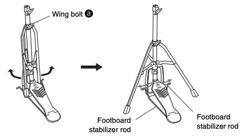
- Loosen the hi-hat stand’s wing bolt a.
- Open up the three legs as shown below and then retighten the wing bolt a to lock them in place.
- Insert the footboard stabilizer rods into the frame holes as shown below.

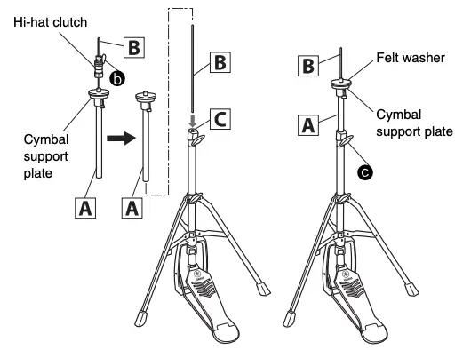
- Loosen the hi-hat clutch’s wing bolt b and remove the hi-hat clutch.
* The hi-hat clutch is not required when assembling the electronic drum kit in the standard fashion described in this manual. Instead, the hi-hat clutch that came with the RHH135 Real Hi-hat Pad will be used. - Remove the hi-hat shaft B from the upper tube A.
- Insert the hi-hat shaft B removed in Step 6 as far as it will go into the lower tube C and screw in the tip.
- Insert the upper tube A over the hi-hat shaft B and tighten the wing bolt c to secure it in place with the cymbal support plate approximately half way between the top of the lower tube C and the top of the hi-hat shaft B.
- Remove the felt pad attached above the cymbal support plate. It is not required when assembling the electronic drum kit in the standard fashion described in this manual.
- Assemble the RHH135 Real Hi-hat Pad.
* For detailed instructions, refer to the “Setting Up” in the RHH135 Owner’s Manual.
Assembling the drum trigger module and cymbal pads
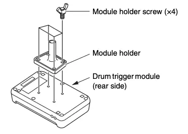
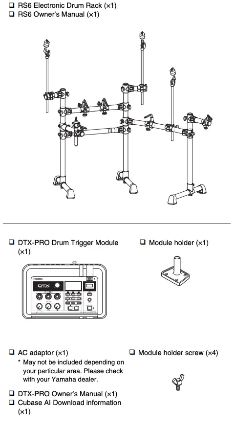
- Drum trigger module
- Secure the module holder to the bottom of the drum trigger module using the module holder screws.
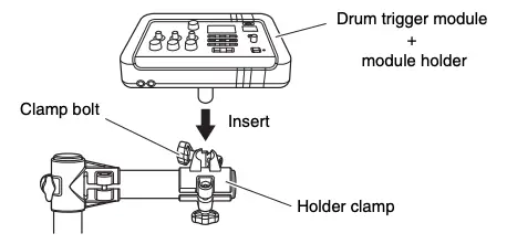
- Push the module holder into the holder clamp and tighten the clamp bolt to secure it in place.
- Cymbal pads
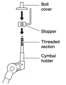
- Using the drum key, loosen the stopper’s key bolt.
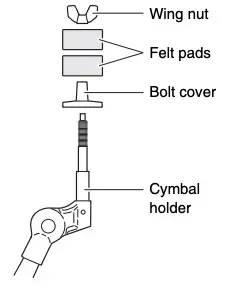
- Remove the wing nut, the two felt pads, and the bolt cover from the cymbal holder.
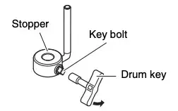
- Place the stopper on the cymbal holder.
* If the key bolt was not sufficiently loosened in Step 1 above, it may not be possible to pass the stopper over the cymbal holder’s shaft. In such a case, loosen the key bolt as much as possible without removing it. - Replace the bolt cover.
* Turn the bolt cover to tighten it onto the threaded section and firmly secure it in place.
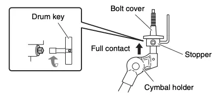
- With the stopper making full contact with the bottom surface of the bolt cover as shown below, tighten the stopper’s key bolt using the drum key.
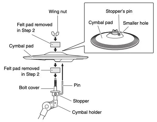
- Place one of the felt pads removed in Step 2 on the cymbal holder.
- Mount the pad on the cymbal stand. Lower the pad into place with the cymbal holder’s shaft passing through the central hole. When mounted, the stopper’s pin should rest inside the pad’s smaller hole.
* If you were to play your cymbal pad without the stopper’s pin positioned well inside the smaller hole, the pad could rotate, causing the pin to be pulled out. It is very important, therefore, to ensure that the stopper is secured as shown in Step 5 above. - Assemble the other felt pad removed in Step 2 to the cymbal holder.
- Tighten the wing nut to secure the pad to the cymbal holder.
Assembling the kick pad
- If a drum mat (sold separately) is not available, lay a sheet of cardboard on the floor to prevent it from being scratched.
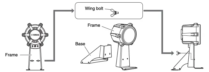
- Remove the two wing bolts from the kick pad frame, and then place them nearby.
- Join the base to the frame as shown on the right, and then secure it in place by the wing bolts removed in the previous step from the base side.
NOTE
For details on assembling the foot pedal (sold separately), refer to the “Assembling the KP90” in the KP90 Owner’s Manual.
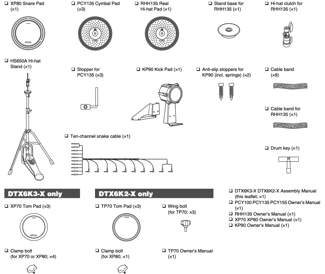
- Open the boxes to reveal their contents.
After opening up the packages containing your electronic drum kit, please verify that all of the following components are present.
Components of both DTX6K3-X and DTX6K2-X
- Assemble the RS6 Electronic Drum Rack.
For instructions on how to assemble the RS6 Electronic Drum Rack, refer to the Owner’s Manual that came with it. - Assemble the pads and the drum trigger module to the electronic drum rack.
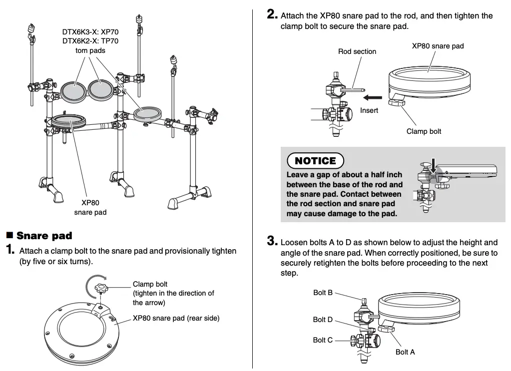
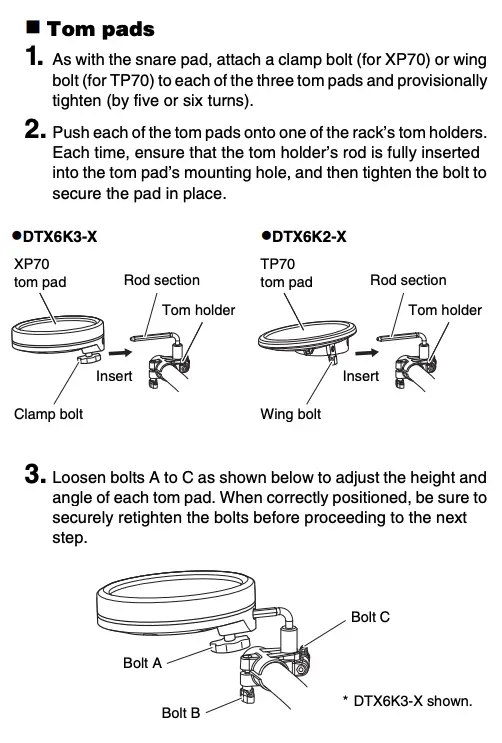
Assembling the snare and tom pads
- Arrange the hi-hat stand and the kick pad as shown in Example of standard assembly on the other side of this sheet.
NOTICE- Lay a drum mat (sold separately) on the floor underneath the hi-hat stand and the kick pad. Alternatively, you can place cardboard from the drum kit packaging or the like on the floor to prevent it from being scratched.
- Ensure that you do not lower the electronic drum rack’s center strut too much as doing so may cause it to come into contact with the kick pad.
- Connect the pads to the drum trigger module.
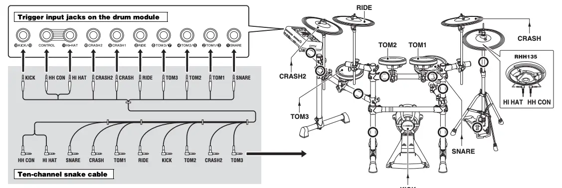
As described below, connect the output of each pad to the corresponding trigger input jack on the drum trigger module.- Plug the straight ends of the ten-channel snake cable into the trigger input jacks on the back of the drum trigger module.
- When using the standard setup, the stickers on each of the snake cable’s plugs will indicate the name of the corresponding pad.
- Plug the L-shaped ends of the ten-channel snake cable into the corresponding pads.
- Wrap the cables for the snare pad, the tom pads, the cymbal pads and the hi-hat pad around the cable clips to prevent them from being pulled out.
NOTICE
Excessive bending can damage pad cables. Ensure, therefore, that these cables are not bent at an extreme angle when wrapped around the clips.
- Using the cable bands, secure the cables to the electronic drum rack at the positions circled in the figure on the right. ( O )
If you secure the cable band from the side closer to the drum trigger module, you can make connections more easily.
- Plug the straight ends of the ten-channel snake cable into the trigger input jacks on the back of the drum trigger module.
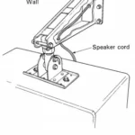
- Connect the drum trigger module to a power supply.
- Plug the AC adaptor’s DC cord into the
 connector. Hook the AC adaptor’s DC cord around the cord clip to secure it in place.
CAUTION
Excessive bending can damage AC adaptor’s DC cord. Ensure, therefore, that the cord is not bent at an extreme angle when wrapped around the clips. Doing so can cause fire or electrical shock.
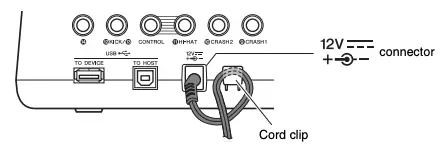
- Plug the adaptor’s AC cord into a domestic wall socket.
- Plug the AC adaptor’s DC cord into the
- Setting up the drum trigger module.
According to your particular electronic drum kit, select the “DTX6K3-X” or the “DTX6K2-X” trigger setup on your drum trigger module. (For details on the trigger setup procedure, refer to the “Initial Settings (Trigger Setup Wizard)” in the DTX-PRO Owner’s Manual.)
The selection of the trigger setup is very important. Selecting the wrong trigger setup will adversely affect your ability to perform comfortably. Use the correct trigger setup that corresponds to your particular electronic drum kit for optimum performance.
- Kick pad output (LEVEL) adjustment:
Adjust the trigger output to your desired setting by using the KP90 kick pad’s level adjustment knob. For details, refer to the “Adjusting the Output Level” in the KP90 Owner’s Manual.
IMPORTANT
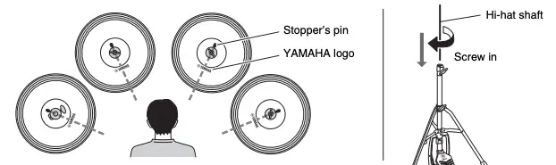
- You can play comfortably by striking near the YAMAHA logo. Adjust the height, angle and orientation of the cymbal pad and hi-hat pad to a position where you can hit around the YAMAHA logo naturally when performing. The correct setting position is that the YAMAHA logo of the cymbal pad and hi-hat pad are visible in front of the performer. The direction of the cymbal pad will be appropriate by adjusting the direction of the stopper as shown on the right. The direction of the hi-hat pad will also be appropriate by adjusting the direction of the hi-hat clutch.
- The hi-hat shaft will become loose while you continue to use the hi-hat, and the hi-hat pad may rotate. Since this may adversely affect performance, screw in the hi-hat shaft periodically and adjust the position of the hi-hat pad.
Your electronic drum kit is now ready.
* For instructions on turning on the drum trigger module, producing sounds, and other subsequent steps, please refer to the Owner’s Manual that came with the module.