![]()
AMAX-4800 Series
Industrial EtherCAT Slave Modules
Startup Manual
Packing List
Before installation, please check that the following items are included in the shipment:
- 1×AMAX-4800 module
- 2 × Terminal blocks (see Specifications for more details)
- 1×AMAX-4800 startup manual
If any of these items are missing or damaged, contact your distributor or sales representative immediately.
User Manual
For more detailed information about this product, download the latest user manual from the Advantech website.
EtherCAT Slave Information File
The AMAX-4800 EtherCAT slave information (ESI) file can be downloaded from the Advantech website at http://r.advantech.com/q5.
Every ESI file contains the configuration data of an EtherCAT slave module. Various EtherCAT communication settings can be defined from the ESI files of connected slave units as well the network connection information. ESI files are saved to the configuration tool to provide network configuration data. Subsequently, the network configuration data can be downloaded to an EtherCAT master unit for configuring an EtherCAT network.
For more information about this or other Advantech products, please visit our website at
http://www.advantech.com
http://www.advantech.com/eplatform
For technical support and service, please visit our support website at
http://support.advantech.com This manual is for the AMAX-4800 series modules. Part No. 2001483002
Printed in Taiwan
Edition 3 January 2019
Overview
The AMAX-4800 series comprises industrial EtherCAT slave modules equipped with the EtherCAT protocol. The modules’ compact size and integrated DIN-rail mount kit ensure easy installation in a variety of cabinets. The modules also feature euro-type pluggable terminal blocks and LED indicators that facilitate system setup and maintenance. All modules are equipped with an isolation circuit that ensures current protection for demanding industrial applications.
Specifications
General
- Connectors
– 10-pin terminal block (3.81 mm) * N
(AMAX-4830/30SO/33/34/50: N = 4,
AMAX-4855/56: N = 8,
AMAX-4860: N = 3,
AMAX-4862: N = 6)
– 3-pin screw terminal block (3.81 mm) * 2 (power)
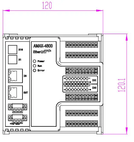
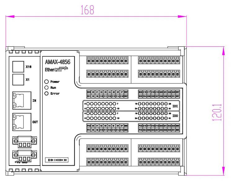
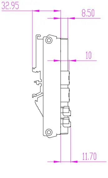
– RJ-45 * 2 (EtherCAT) - Dimensions
AMAX-4830/30SO/33/34/50/60: 120 x 120 x 40 mm
AMAX-4855/56/62: 168 x 120 x 40 mm
- Operating Temperature: -20 ~ 60 °C (32 ~ 140 °F)
- Storage Temperature: –40 ~ 70 °C (-40 ~ 158 °F)
- Storage Humidity: 5 ~ 95% RH (non-condensing)
- Power Supply: 10 ~ 30 VDC
Communications
- Interface: EtherCAT
- Data Transfer Medium: Ethernet/EtherCAT cable (CAT5 min.), shielded
- Distance Between Modules: 100 m max.(100BASE-TX)
- Communication Cycle Time: 100 us
- Data Transfer Rate: 100 Mbps
- Configuration: Not required
Digital Input
- Channels
– AMAX-4830/4830SO/4850/4862: 16 channels
– AMAX-4833/4855/4856: 32 channels
– AMAX-4860: 8 channels - Input Voltage
– Logic 0: 3 V max.
– Logic 1: 10 V min. (30 V max.) - Isolation Protection: 2,500 VDC
AMAX-4800 Startup Manual 1
Digital Output
- Channels
– AMAX-4830/4830SO: 16 channels
– AMAX-4834/4856: 32 channels - Load Voltage: 5 ~ 40 VDC
- Load Current
– 350mA/channel (sink)@25 °C
– 250mA/channel (sink)@60 °C AMAX-4830SO:
– 250mA/channel (source)@25 °C
– 200mA/channel (source)@60 °C - Isolation Protection: 2,500 VDC
- Opto-Isolator Response Time: 100 us
PhotoMOS Relay Output
- Channels
AMAX-4850: 8 channels
AMAX-4855: 16 channels - Relay Type: PhotoMOS SPST (Form A)
- Load Voltage: 60 V (AC peak or DC)
- Load Current: 1.2A
- Peak Load Current: 4A @100 ms (1 pulse)
- Isolation Protection: 1,500 VDC Rotary Switch
- Turn-On Time: 1 ms typical
- Turn-Off Time: 0.6 ms typical
Relay Output
- Channels
AMAX-4860: 8 channels
AMAX-4862: 16 channels - Relay type: Form A
- Contact Rating (Resistive): 2A@250 VAC , 2A@30 VDC
- Max. Switching Power: 500 VA , 60W
- Max. Switching Voltage: 270 VAC , 125 VDC
- Resistance: 30 mΩ max.
- Operating Time: 10 ms max.
- Releasing Time: 5 ms max.
- Life Expectancy – Mechanical: 2 x 10 7 ops. at no load – Electrical: 3 x 10 4 ops. @2A/250 VAC
Installation
- Download the AMAX-4800 user manual and ESI file from the Advantech website (http://r.advantech.com/q5).
- Import the ESI file to create an EtherCAT network information (ENI) file using either (1) Advantech Common Motion Utility (with a PCI-1203 EtherCAT master card) (2) Other EtherCAT master software, such as TwinCAT or Acontis
- Use the master utility to test the AMAX-4800 modules.
Power
AMAX-4800 modules feature two power input terminals, an input power range of 10 ~ 30 VDC, and power redundancy support. For modules connected to two power input
sources, if one source is inactive or interrupted, the other power source can take over immediately. The AMAX-4800 modules can operate with only a single power source.
2 AMAX-4800 Startup Manual
Declaration of Conformity
FCC Class A
This equipment has been tested and found to comply with the limits for a Class A digital device, pursuant to part 15 of • Channels – AMAX-4830/4830SO: 16 channels – AMAX-4834/4856: 32 channels the FCC Rules. These limits are designed to provide rea- • Load Voltage: 5 ~ 40 VDC reasonable protection against harmful interference when the equipment is operated in a commercial environment. This equipment generates, uses, and can radiate radio frequency energy and, if not installed and used in accordance with the instruction manual, may cause harmful interference to radio communications. The operation of this equipment in residential areas is likely to cause interference. In such cases, users are required to correct the interference at their own expense.
CE
This product has passed the CE test for environmental specifications when shielded cables are used for external wiring. We recommend the use of shielded cables. Advantech does provide shielded cables. Contact your local supplier for ordering information.
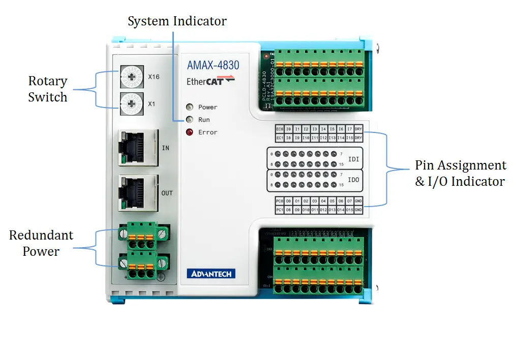
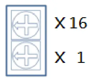
Rotary Switch
AMAX-4800 modules use two hexadecimal rotary switches to represent the slave ID (range: 0 ~ 255).
 For example, if a user arranges the rotary switches following the sequence “4, F”, the slave ID will be set as “4 x 16 + F x 1= 79”.
Dip Switch
AMAX-4830SO
AMAX-4830SO provides separated COM connections in groups of eight digital input/output channels. As a default, EC0, EC1, PC0, and PC1 are isolated from each other. However, for cases where EC0 and EC1, or PC0 and PC1, need to be connected together, this can be achieved using SW2 and SW3. EC0 and EC1 are connected together when the SW2 switch is in the up (open) position. Similarly, PC0 and PC1 are connected together when the SW3 switch is in the up (open) position.
 |
SW2/SW3 Switch in the Up Position EC0 & EC1 Open PC0 & PC1 Open |
 |
SW2/SW3 Switch in the Down Position EC0 & EC1 Close PC0 & PC1 Close |
LEDs
Power Indicator
| Indicator State | System State | Description |
| Off | Power off | The system is not on/ power is off |
| On | Power on | The system is on/ power is on |
Run Indicator
| Indicator State | Slave State | Condition |
| Off | Initialization | The device is in the Initialization state |
| Blinking | Pre-Opera- tional | The device is in the Pre-Operational state |
| Single flash | Safe Operational | The device is in the Safe Operational state |
| On | Operational | The device is in the Operational state |
| Flickering | Bootstrap | The device is booting and has not yet entered the Initialization state/the device is in the Bootstrap state/ firmware download in progress |
Error Indicator
| Indicator State | Error Name | Description |
| Off | No error | The device is in working condition |
| Blinking | Invalid configu- ration | General configuration error |
| Single flash | Local error | A slave device application has changed the EtherCAT state autonomously due to local error/the error indicator bit is set to 1 in the AL Status register |
| Double flash | Watchdog timeout | An application watchdog timeout has occurred |
Link Indicator (on RJ-45)
| Indicator State | Link | Activity | Description |
| On | Yes | No | Port open/connected |
| Flickering | Yes | Yes | Port open/connected |
| Off | No | Not applicable | Port closed/disconnected |
Dimensions


Connections
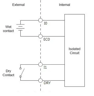
Isolated Digital Inputs
All isolated digital input channels accept voltages between 10 VDC and 30 VDC . Every eight input channels share one external common collector (channels 0 ~ 7 use EC0 and channels 8 ~ 15 use EC1). The diagram below shows how an external input source should be connected to the module’s isolated inputs.
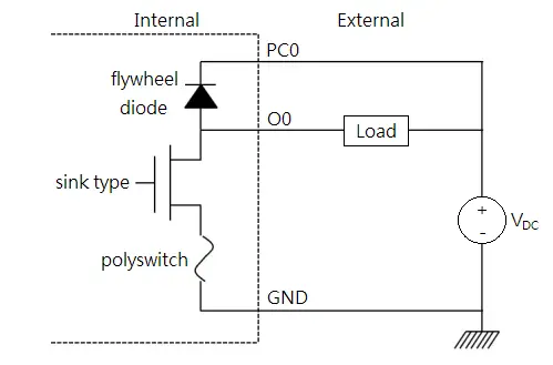
Isolated Digital Outputs
If an external voltage source (5 ~ 40 V) is connected to each isolated output channel (On) and the isolated digital output is turned on (350 mA max./channel), the module current will sink from the external voltage source. IDO modules provide EGND pins for IDO connections. The diagrams below show how an external output load should be connected to the module’s isolated outputs.
Relay Outputs
The layout and connections of the relay outputs are shown in the diagram below.