MIC-7700
Intel® 6th/7th
Generation Core™ i Socket Compact
Fanless System
Startup Manual
Packing List
Before you begin installing your card, please make sure that the following items have been shipped:
| 1. MIC-7700 bare-bone system x 1 | |
| 2. Startup manual ENCNTC for MIC-7700 1st Ed | P/N: 2001770030 |
| 3. MIC-7700 Driver CD x 1 | P/N: 2061770010 |
| 4. 4-pin Phoenix connector | P/N: 1652003234 |
| 5. Mounting bracket x2 | P/N: 1960070543N001 |
| 6. SATA cable x1 | P/N: 1700013095 |
| 7. SATA power cable x 1 | P/N: 1700024372-01 |
| 8. 2 x DB9 ports cable x 1 | P/N: 1701200220 |
If any of these items are missing or damaged, please contact your distributor or sales representative immediately.
Note 1: For detailed info about the MIC-7700, please refer to information on the enclosed CD-ROM (in PDF format).
Note 2: Acrobat Reader is required to view any PDF file. Acrobat Reader can be downloaded at: get. adobe.com/reader (Acrobat is a trademark of Adobe)
Caution: DANGER OF EXPLOSION IF BATTERY IS INCORRECTLY REPLACED. REPLACE ONLY WITH THE SAME OR EQUIVALENT TYPE RECOMMENDED BY THE MANUFACTURER, DISCARD USED BATTERIES ACCORDING TO THE MANUFACTURER’S INSTRUCTIONS.
For more information on this and other Advantech products, please visit our website at:
http://www.advantech.com
For technical support and service, please visit our support website at:
http://support.advantech.com.tw/support/default.aspx
This manual is for the MIC-7700 Series Rev. A1.
Part No. 2001770030
Printed in China
1st Edition
April 2018
Specifications
Processor System
• Intel ® 6 th /7 th generation Core™ i socket CPU (LGA1151)
Memory
• Supports dual channel DDR4 SODIMM-2133 MHz, 16 GB per slot without ECC function; Max. capacity is 32GB
Graphics
• Q170: Intel ® HD Graphics 530, supports DirectX 12
• H110: Intel ® HD Graphics 510, supports DirectX 12
Serial Ports
• 2 x RS-232/422/485, RS-485 supports automatic flow control
• 2 x RS232 Ethernet • Interface: 10/100/1000 Mbps
• Controller: Q170 LAN1: Intel ® I219LM,
LAN2:
Intel ® i210IT H110 LAN1: Intel ® I219V, LAN2: Intel ® i210IT
Storage
• Internal 2.5” Storage Bay: 1
• CFast slot: 1
• mSATA: 1
Front I/O
• Display: 1 x VGA, 1 x DVI
• USB:
Q170: 8 x USB 3.0
H110: 4 x USB 3.0 and 4 x USB 2.0
• Serial: 2 x RS-232/422/485, 2 x RS-232
• Audio: Line-out/Mic-in
Power Requirement
• Power type: ATX/AT
• Power input Voltage: 9-36 VDC
• Minimum Power Input: 9VDC 16A – 36VDC 5A This product is intended to be supplied by a UL certified power supply or UL certified DC source rated 19Vdc, 7.89A minimum, TMA 50 °C minimum, if you need further assistance, please contact Advantech for further information.
Miscellaneous
• Power Switch (Orange: System standby/Green: System Power boot)
• COM1 TX & RX LED; COM2 TX & RX LED; Storage Status LED Environment
• Operation Temperature:
TDP 35W CPU: -10~50°C
TDP 65W CPU: -10~40°C (not support i7)
Note: Safety Certification Test Temperature: safety max 50 °C with SSD (TDP 35W CPU)
• Storage Temperature: -40 ~ 85 °C (-40 ~ 185 °F)
• Relative Humidity: 95% @ 40° C (non-condensing)
MIC-7700 Startup Manual 1
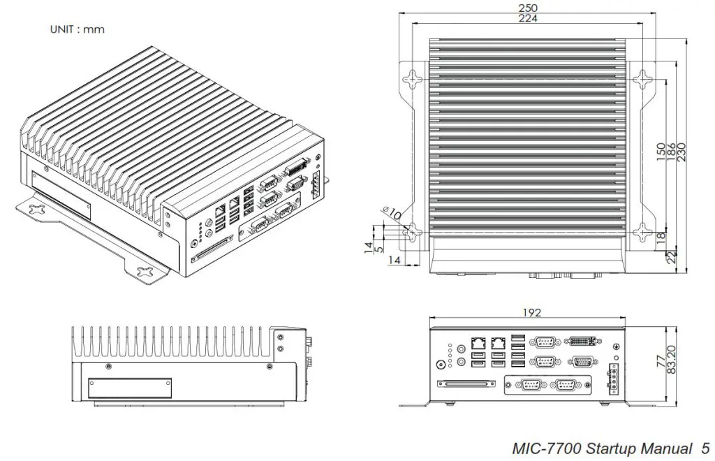
Physical Characteristics
- Dimensions (WxHxD): 77 x 192 x 230 mm
- Weight: 2.8 kg (6.17 lbs)
Jumpers and Connectors
The board has a number of jumpers that allow you to configure your system to suit your application. The table below lists the function of each of the jumpers and connectors.
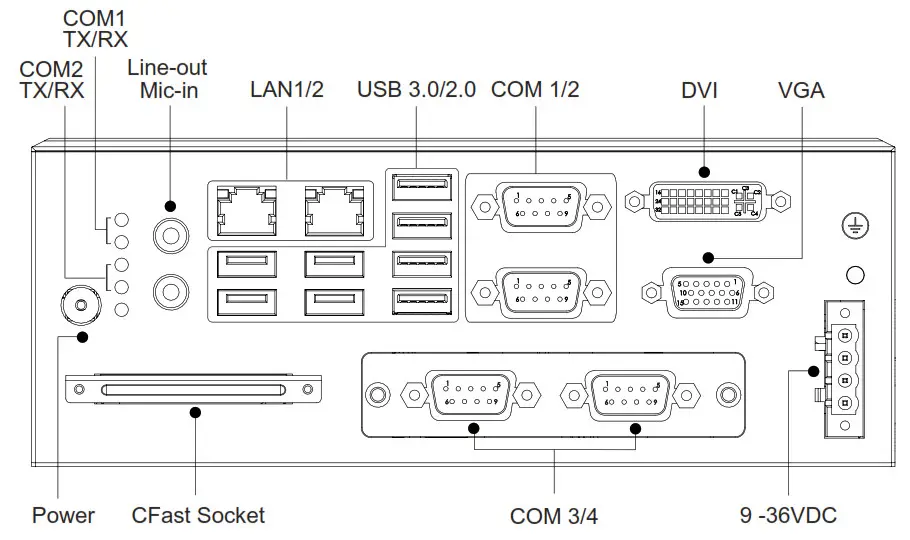
| Connectors | |
| Label | Function |
| VGA1 | VGA Connector |
| DVI1 | DVI connector |
| COM 12 | RS-232/422/485 |
| COM 34 | RS-232 |
| USB 12 | USB 3.0 |
| USB 34 | USB 3.0 |
| USB 5678 | USB3.0 (Q170) or USB2.0 (H110) |
| LAN 1 | Intel i219LM (Q170) or Intel i219V (H110) |
| LAN 2 | Intel i210IT |
| Audio | Audio Jack (Line-out, Mic-in) |
| LED 1234 | COM 1/2 TX; RX; LED |
| LED 5 | Storage device status |
| DC 9-36V | Power connector |

| PSON1: System AT/ATX Module Selection | |
| Function | Jumper Setting |
| 2-Jan | AT module |
| 3-Feb | ATX module (Default) |
Software Installation
The drivers for the MIC-7700 are located on the software installation CD. Please click through the folder and follow the on-screen instructions to install them. The computer is supplied with a battery-powered real-time clock circuit. There is a danger of explosion if the battery is incorrectly replaced. Replace only with the same or equivalent type recommended by the manufacturer. Discard used batteries according to the manufacturer’s instructions.
2 MIC-7700 Startup Manual
Declaration of Conformity
This device complies with the requirements in Part 15 of the FCC rules. Operation is subject to the following two conditions:
1. This device may not cause harmful interference;
2. This device must accept any interference received, including interference that may cause undesired operation.
System I/O Interface
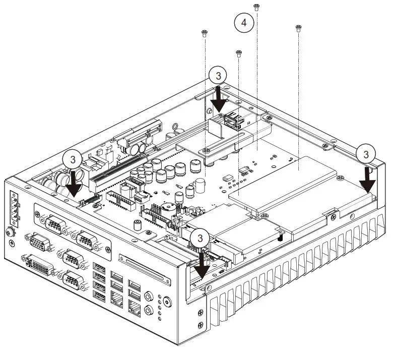
Simple Maintenance Process
Memory Installation
MIC-7700 supports DDR4 SO-DIMM non-ECC type memory module. If you need a detailed memory support list, please contact your distributor or sales representative to order compatible memory modules.
- Undo 4 screws and remove the bottom cover.
- Undo 4 screws to remove the storage tray.
- Undo 3 screws to remove memory thermal cover.
- Affix thermal pad (P/N: 1990019498N000) on memory and assemble memory.
Note 1: Thermal pad and memory thermal cover must be fully mated and compacted.
Storage Installation
- Undo 4 screws and remove the bottom cover
- Undo 4 screws to remove storage tray.
- Secure the 4 x screws (P/N:1930002235)
- Assemble SATA cable/power cable and replace storage tray; secure with 4x screws.
- Replace bottom cover.
Mini-PCIE Installation
MIC-7700 supports one full size Mini-PCIE.
- Undo 4 screws and remove the bottom cover
- Install the module in the Mini-PCIe socket and secure with screws.
- Replace bottom cover and secure with screws.
Internal USB 2.0 Installation
- Undo 4 screws and remove the bottom cover.
- Loosen the screw and adjust bracket size in accordance with USB dongle size.
- Install USB dongle in the first socket. Only the first socket has a function.
- Secure the screw and replace the bottom cover and secure with screws.
CPU Installation
- Undo 4 screws and remove the bottom cover.
- Undo 4 screws to remove storage tray.
- Undo 4 screws in the corner of chassis.
- Undo 4 screws around CPU to release AL heatsink.
- Remove AL heatsink and install CPU.
- Smear thermal grease to CPU.
- Replace AL heatsink, storage tray and bottom cover.
Mounting Kit Installation
1. Take the mounting kit from accessory box.
2. Secure the 4x screws (P/N: 1930001069) and install system on table.
MIC-7700 Startup Manual 3
Safety Instructions
- Read these safety instructions carefully.
- Keep this Startup Manual for later reference.
- Disconnect this equipment from any AC outlet before cleaning. Use a damp cloth. Do not use liquid or spray detergents for cleaning.
- For plug-in equipment, the power outlet socket must be located near the equipment and must be easily accessible.
- Keep this equipment away from humidity.
- Put this equipment on a reliable surface during installation. Dropping it or letting it fall may cause damage.
- The openings on the enclosure are for air convection. Protect the equipment from overheating. DO NOT COVER THE OPENINGS.
- Make sure the voltage of the power source is correct before connecting the equipment to the power outlet.
- Position the power cord so that people cannot step on it. Do not place anything over the power cord.
- All cautions and warnings on the equipment should be noted.
- If the equipment is not used for a long time, disconnect it from the power source to avoid damage by transient overvoltage.
- Never pour any liquid into an opening. This may cause fire or electrical shock.
- Never open the equipment. For safety reasons, the equipment should be opened only by qualified service personnel.
- If one of the following situations arises, get the equipment checked by service personnel:
• The power cord or plug is damaged.
• Liquid has penetrated into the equipment.
• The equipment has been exposed to moisture.
• The equipment does not work well, or you cannot get it to work according to the user’s manual.
• The equipment has been dropped and damaged.
• The equipment has obvious signs of breakage. - DO NOT LEAVE THIS EQUIPMENT IN AN ENVIRONMENT WHERE THE STORAGE TEMPERATURE MAY GO BELOW -40° C (-40° F) OR ABOVE 85° C (185° F). THIS COULD DAMAGE THE EQUIPMENT. THE EQUIPMENT SHOULD BE IN A CONTROLLED ENVIRONMENT.
- CAUTION: DANGER OF EXPLOSION IF BATTERY IS INCORRECTLY REPLACED. REPLACE ONLY WITH THE SAME OR EQUIVALENT TYPE RECOMMENDED BY THE MANUFACTURER, DISCARD USED BATTERIES ACCORDING TO THE MANUFACTURER’S INSTRUCTIONS.
- The sound pressure level at the operator’s position according to IEC 704-1:1982 is no more than 70 dB (A).
- RESTRICTED ACCESS AREA: The equipment should only be installed in a Restricted Access Area. DISCLAIMER: This set of instructions is given according to IEC 704-1. Advantech disclaims all responsibility for the accuracy of any statements contained herein.