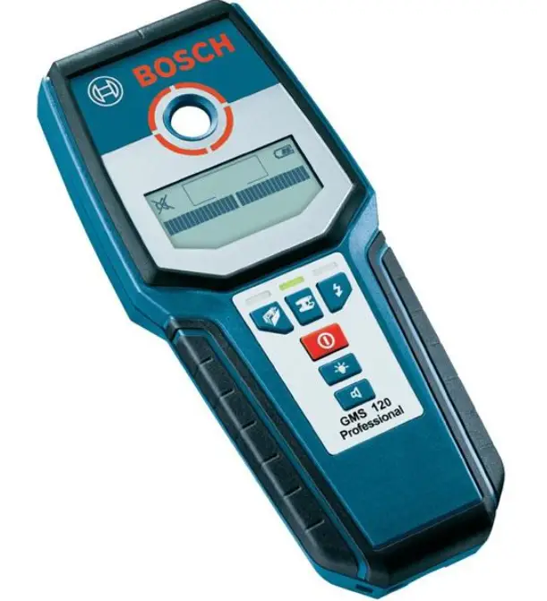

BOSCH GMS 120 Professional Stud Finder Detection

Overview
Instructions
Safety Notes
Read and observe all instructions. SAVE THESE INSTRUCTIONS FOR FUTURE REFERENCE.
- Have the measuring tool repaired only through qualified specialists using original spare parts. This ensures that the safety of the measuring tool is maintained.
- Do not operate the measuring tool in explosive environments, such as in the presence of flammable liquids, gases or dusts. Sparks can be created in the measuring tool which may ignite the dust or fumes.
Functional Description
Please unfold the fold-out page with the repre-sentation of the measuring tool and leave it un-folded while reading the operating instructions.
Intended Use
The measuring tool is intended for the detection of metals (ferrous and non-ferrous metals, e.g., rebar), joists and “live” wires/conductors in walls, ceilings and floors.
Product Features
The numbering of the product features shown refers to the illustration of the measuring tool on the graphic page.
- Illuminated ring
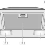
- Marking hole
- Display
- Operating-mode indication
- On/Off button
- Display-illumination button
- Audio signal button
- Button for detecting “live” conductors/ Operating mode “Power cable”
- Button for metal detection/Operating mode “Metal”
- Button for detecting wood and metal beams/Operating mode “Drywall”
- Contact pads
- Sensor area
- Type plate
- Battery lid
- Latch of battery lid
- Fixture for carrying strap
- Protective pouch
- Carrying strap
Accessories shown or described are not part of the standard delivery scope of the product. A complete overview of accessories can be found in our acces-sories program.
Display Elements (see figure A)
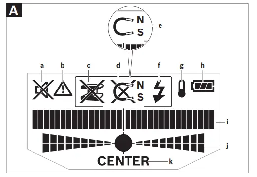
- a Switched-off audio signal indicator
- b Warning-function indicator
- c Indication of the object type “Non-metal object”
- d Indication of the object type “Non-magnetic metal”
- e Indication of the object type “Magnetic metal”
- f Indication of the object type “Live conductor”
- g Temperature control indicator
- h Battery indicator
- i Measuring indicator
- j Fine scale
- k Indication “CENTER”
Technical Data
Digital Detector GMS 120 Professional
Article number 3 601 K81 000
Maximum scanning depth*
- Ferrous metals: 120 mm
- Non-ferrous metals (copper): 80 mm
- Live conductors 110 V/230 V (voltage applied): 50 mm
- Wood: 38 mm
- Automatic switch-off after approx: 5min
- Operating temperature: –10 °C … +50 °C
- Storage temperature: –20°C … +70°C
- Battery: 1 x 9 V 6LR61
- Operating life time, approx: 5h
- Weight according to EPTA-Procedure 01/2003: 270 g
Note: depending on operating mode, material and size of the objects, as well as material and condition of the base material
Note: less scanning depth for wires/conductors that are not “live” Please observe the article number on the type plate of your measuring tool. The trade names of the individual measuring tools may vary.
Declaration of Conformity
We declare under our sole responsibility that the product described under „Technical Data“ is in conformity with the following standards or standardization documents:
EN 61010-1:2001-03, EN 61326-1:2006-05, EN 301489-3:2002-08, EN 301489-1:2008-04, EN 300330-1:2010-02, EN 300330-2:2010-02 according to the provisions of the directives 2004/108/EC, 1999/5/EC.
Dr. Egbert Schneider Senior Vice President Engineering 
Dr. Eckerhard Strötgen Head of Product Certification 
Robert Bosch GmbH, Power Tools Division D-70745 Leinfelden-Echterdingen Leinfelden, 29.04.2010
Assembly
Inserting/Replacing the Battery
Alkali-manganese batteries are recommended for the measuring tool.
To open the battery lid 14, press the latch 15 in the direction of the arrow and fold up the bat-tery lid. Insert the supplied battery. Pay atten-tion that the polarity is correct, according to the representation on the inside of the battery lid. The battery indicator h always indicates the cur-rent battery status:
 Battery fully charged
 Battery has 2/3 of its capacity or less
 Battery has 1/3 of its capacity or less
 Please change battery
If the measuring tool is not used for a long period of time, the battery must be re-moved. The battery can corrode or discharge itself over long periods.
Operation
- Protect the measuring tool against moisture and direct sun light.
- Do not subject the measuring tool to extreme temperatures or variations in tem-perature. In case of large variations in tem-perature, allow the measuring tool to adjust to the ambient temperature before switch-ing it on. In case of extreme temperatures or variations in temperature, the accuracy of the measuring tool and the display indication can be impaired.
- Use or operation of transmitting systems, such as WLAN, UMTS, radar, transmitter masts or microwaves, in the close proximity can influence the measuring function.
Initial Operation
Switching On and Off
- Before switching the measuring tool on, make sure that the sensor area 12 is not moist. If required, dry the measuring tool us-ing a soft cloth.
- If the measuring tool was subject to an extreme temperature change, allow it to ad-just to the ambient temperature before switching on.
To switch on the measuring tool, press the On/Off button 5.
To switch off the measuring tool, press the On/Off button 5 again.
When no button on the measuring tool is pressed for approx. 5 minutes and when no ob-jects are detected, the measuring tool automat-ically switches off to save the battery.
Switching the Display Illumination On/Off The display illumination can be switched on/off with display-illumination button 6. Switching the Audio Signal On/Off
The audio signal can be switched on/off with the audio signal button 7. When the audio signal is switched off, indication a appears on the dis-play.
Method of Operation (see figures A–B)
The measuring tool checks the base material of sensor area 12 in measurement direction A to the max. detection depth (see “Technical Da-ta”). Objects are detected that differ from the material of the wall.
Always move the measuring tool in a straight line over the surface applying slight pressure, without lifting it off or changing the pressure. During measurement, the contact pads 11 must always have contact to the surface.
Measuring Procedure
Position the measuring tool on/against the sur-face being detected, and move it in direction B. When the measuring tool comes closer to an ob-ject, the amplitude in measuring indicator i in-creases and ring 1 lights up yellow; when it is moved away from the object, the amplitude de-creases. Measuring indicator i indicates the maximal amplitude above the centre of the ob-ject; ring 1 lights up red and an audio signal sounds. For small or deeply embedded objects, ring 1 can continue to light up yellow, while there is no audio signal.
- Wide objects are not indicated by the illuminated ring or the audio signal throughout their complete width.
To localise the object more precisely, move the measuring tool repeatedly (3x) back and forth over the object. The fine scale j is automatically activated in all operating modes. Fine scale j in-dicates a full amplitude when the object is be-low the centre of the sensor or when the maxi-mum amplitude of measuring indicator i is reached. In the operating modes “Drywall” and “Metal”, the indication “CENTER” k lights up additionally.
Wider objects in the base material are detected through a continuous, high amplitude of meas-uring indicators i and j. Ring 1 lights up yellow. The duration of the high amplitude corresponds approximately with the object width. When very small or deeply embedded objects are being sought and measuring indicator i reacts on-ly slightly, move the measuring tool repeatedly over the object in horizontal and vertical direction. Pay attention to the amplitude of fine scale j, and when in operating mode “Drywall” and “Metal”, additionally to the “CENTER ” k indica-tion, which will then allow for precise detection.
Operating Modes
The best measuring results are achieved through selection of the operating modes. The maximal detection depth for metal objects is achieved in the operating mode “Metal”. The maximal detection depth for “live” conductors is achieved in the operating mode “Power cable”. The selected operating mode can be recognized at any time via the green illuminated operating-mode indication 4.
Drywall
The operating mode “Drywall” is suitable for de-tecting wood or metal objects in drywalls.
Press button 10 to activate the operating mode “Drywall”. The operating-mode indication 4 above button 10 lights up green. As soon as the measuring tool is positioned against the base material to be detected, ring 1 lights up green and signals operational readiness. In the operating mode “Drywall” all object types are detected and indicated:
- Non-metal, e.g. a wood beam
- Magnetic, e.g. reinforcing steel
- Non-magnetic, but metal, e.g. copper pipe
- “Live”, e.g. a “live” conductor
Notes: In the operating mode “Drywall”, other objects, apart from wood and metal objects and “live” conductors are also detected, such as plastic tubing filled with water. For such ob-jects, the indication c for non-metal objects is indicated in display 3.
Nails and screws in the base material may cause a wooden beam to be indicated as a metal ob-ject on the display.
When display 3 indicates a continuously high amplitude of measuring indicator i and fine scale j, restart the measuring procedure again by positioning the measuring tool at a different location on the base material.
When the illuminated ring 1 does not signal op-erational readiness when positioning the meas-uring tool on the base material being detected, the measuring tool cannot properly detect the base material.
- Press and hold button 10 until the illuminat-ed ring lights up green.
- When starting a new measuring procedure afterwards and positioning the measuring tool onto a different wall or surface, you must briefly press button 10.
- In rare cases, the measuring tool may not be able to detect the base material because the side with the sensor area 12 and the type plate 13 is soiled or dirty. Clean the measur-ing tool with a dry, soft cloth and restart the measuring procedure.
Metal
The operating mode “Metal” is suitable for de-tecting magnetic and non-magnetic objects in-dependent of the wall material.
Press button 9 to activate the operating mode “Metal”. The illuminated ring 1 and indication 4 above button 9 light up green.
When the detected metal object is of magnetic metal (e.g. iron), the symbol e is indicated on display 3. For non-magnetic metals, the symbol d is indicated. In order to differentiate between metal types, the measuring tool must be posi-tioned above the detected metal object (ring 1 is lit red).
Note: For reinforcement steel mesh and steel in the examined base material, an amplitude is in-dicated over the complete surface of measuring indicator i. For reinforcement steel mesh, it is typical that the symbol e for magnetic metal is indicated on the display directly above the iron rods, whereas between the iron rods, the sym-bol d for non-magnetic metal will appear.
Power Cable
The operating mode “Power cable” is suitable only for detecting “live” conductors (110–230 V).
Press button 8 to activate the operating mode “Power cable”. The illuminated ring 1 and indi-cation 4 above button 8 light up green.
When a “live” conductor is detected, indication f appears on the display 3. Move the measuring tool repeatedly over the area to localise the “live” conductor more precisely. After moving over the “live” conductor several times, it can be indicated very accurately. When the measuring tool is very close to the conductor, the illuminat-ed ring 1 flashes red and the audio signal beeps swiftly.
Notes:
- “Live” conductors are indicated in any oper-ating mode.
- “Live” conductors can be detected easier when power consumers (e.g. lamps, ma-chines) are connected to the sought conduc-tor and switched on.
- Under certain conditions (such as below metal surfaces or behind surfaces with high water content), “live” conductors cannot be securely detected. The signal strength of a “live” conductor depends on the position of the cable. Therefore, apply further measure-ments in close proximity or use other infor-mation sources to check if a “live” conductor exists.
- Voltage-free conductors can be detected as metal objects in the operation mode “Metal”. This does not apply for stranded conductors (contrary to solid conductors or cable).
- Static electricity can lead to inaccurate indi-cation of electric lines, e.g., over a large range. To improve the indication, place your free hand flat on the wall next to the measur-ing tool, in order to remove the static elec-tricity.
Working Advice
- Measuring values can be impaired through certain ambient conditions. These include, e.g., the proximity of other equipment that produce strong magnetic or electromagnetic fields, moisture, metallic building materials, foil-laminated insulation materials or con-ductive wallpaper or tiles. Therefore, please also observe other information sources (e.g. construction plans) before drilling, sawing or routing into walls, ceilings or floors.
Marking Objects
If required, detected objects can be marked. Perform a measurement as usual. Once you have found the boundaries or the centre of an object, mark the sought location through the marking hole 2.
Temperature Control
The measuring tool is equipped with a tempera-ture control indicator, as accurate measure-ments are only possible as long as the tempera-ture within the measuring tool remains constant.
When the temperature control indicator g lights up, the measuring tool is not within the operat-ing temperature range or was subject to large variations in temperature. Switch the measur-ing tool off and allow it to adjust to the ambi-ent temperature before switching it on again.
Warning Function
When indicator b lights up on display 3 and indi-cation 4 flashes above button 10, the measure-ment must be restarted. Remove the measuring tool from the wall and place it on the base ma-terial at a different location.
When indicator b flashes on display 3, send the measuring tool in the provided protective pouch to an authorised customer services agent.
Recalibration
When measuring indicator i indicates a continu-ously high amplitude in the operating mode “Metal”, even though there is no metal object near the measuring tool, the measuring tool can be manually recalibrated.
- Switch the measuring tool off.
- Removal all objects near the measuring tool that could be detected, including your wrist watch or rings made of metal, and hold the measuring tool up.
Pay attention that battery indicator h indi-cates at least 1/3 capacity:
Hold the measuring tool in such a manner that the type plate 13 faces toward the ground. Avoid bright light sources or direct sunlight from shining on the area 12 and 13, without covering off this area. - Press and hold buttons 5 and 7 until the illu-minated ring 1 lights up red. Then release both buttons.
- When the calibration was successful, the meas-uring tool will automatically start after a few seconds, and will be ready for operation again.
Note: If the measuring tool does not automatical-ly start, repeat the recalibration. If the measuring tool still does not start, send it in the provided protective pouch to an authorised customer serv-ices agent.
Maintenance and Service
Maintenance and Cleaning
- Check the measuring tool each time before use. In case of visible damage or loose com-ponents inside the measuring tool, safe func-tion can no longer be ensured.
- Keep the measuring tool clean and dry at all times to ensure proper and safe working.
- Do not immerse the measuring tool in water or other fluids.
- Wipe away debris or contamination with a dry, soft cloth. Do not use cleaning agents or solvents. In order not to affect the measuring function, decals/stickers or name plates, especially metal ones, may not be attached in the sensor area 12 on the front or back side of the measuring tool.
- Do not remove the contact pads 11 on the back-side of the measuring tool.
- If the measuring tool should fail despite the care taken in manufacturing and testing procedures, repair should be carried out by an authorised af-ter-sales service centre for Bosch power tools. Do not open the measuring tool yourself.
- In all correspondence and spare parts orders, please always include the 10-digit article number given on the type plate of the measuring tool.
- Store and transport the measuring tool only in the supplied protective pouch.
- In case of repairs, send in the measuring tool packed in its protective pouch 17.
After-sales Service and Customer Assistance
Our after-sales service responds to your ques-tions concerning maintenance and repair of your product as well as spare parts. Exploded views and information on spare parts can also be found under:
www.bosch-pt.com
Our customer service representatives can an-swer your questions concerning possible appli-cations and adjustment of products and accessories.
Great Britain
Robert Bosch Ltd. (B.S.C.)
P.O. Box 98
Broadwater Park
North Orbital Road
Denham
Uxbridge
UB 9 5HJ
Tel. Service: +44 (0844) 736 0109
Fax: +44 (0844) 736 0146
E-Mail: [email protected]
Ireland
Origo Ltd.
Unit 23 Magna Drive
Magna Business Park
City West
Dublin 24
Tel. Service: +353 (01) 4 66 67 00
Fax: +353 (01) 4 66 68 88
Australia, New Zealand and Pacific Islands
Robert Bosch Australia Pty. Ltd.
Power Tools
Locked Bag 66
Clayton South VIC 3169
Customer Contact Center
Inside Australia:
Phone: +61 (01300) 307 044
Fax: +61 (01300) 307 045
Inside New Zealand:
Phone: +64 (0800) 543 353
Fax: +64 (0800) 428 570
Outside AU and NZ:
Phone: +61 (03) 9541 5555
www.bosch.com.au
Republic of South Africa
Customer service
Hotline: +27 (011) 6 51 96 00
Gauteng – BSC Service Centre
35 Roper Street, New Centre Johannesburg
Tel.: +27 (011) 4 93 93 75
Fax: +27 (011) 4 93 01 26
E-Mail: [email protected]
KZN – BSC Service Centre
Unit E, Almar Centre
143 Crompton Street
Pinetown
Tel.: +27 (031) 7 01 21 20
Fax: +27 (031) 7 01 24 46
E-Mail: [email protected]
Western Cape – BSC Service Centre
Democracy Way, Prosperity Park Milnerton
Tel.: +27 (021) 5 51 25 77
Fax: +27 (021) 5 51 32 23
E-Mail: [email protected]
Bosch Headquarters
Midrand, Gauteng
Tel.: +27 (011) 6 51 96 00
Fax: +27 (011) 6 51 98 80
E-Mail: [email protected]
People’s Republic of China
Website: www.bosch-pt.com.cn
China Mainland
Bosch Power Tools (China) Co., Ltd.
567, Bin Kang Road
Bin Jiang District 310052
Hangzhou, P.R.China
Service Hotline: 800 8 20 84 84
Tel.: +86 (571) 87 77 43 38
Fax: +86 (571) 87 77 45 02
HK and Macau Special Administrative Regions
Robert Bosch Hong Kong Co. Ltd.
21st Floor, 625 King’s Road
North Point, Hong Kong
Customer Service Hotline: +852 (21) 02 02 35 Fax: +852 (25) 90 97 62
E-Mail: [email protected]
www.bosch-pt.com.cn
Indonesia
PT. Multi Tehaka
Kawasan Industri Pulogadung
Jalan Rawa Gelam III No. 2
Jakarta 13930
Indonesia
Tel.: +62 (21) 46 83 25 22
Fax: +62 (21) 46 82 86 45/68 23
E-Mail: [email protected]
www.multitehaka.co.id
Philippines
Robert Bosch, Inc.
28th Floor Fort Legend Towers,
3rd Avenue corner 31st Street,
Fort Bonifacio Global City,
1634 Taguig City, Philippines
Tel.: +63 (2) 870 3871
Fax: +63 (2) 870 3870
[email protected]
www.bosch-pt.com.ph
Bosch Service Center:
9725-27 Kamagong Street
San Antonio Village
Makati City, Philippines
Tel.: +63 (2) 899 9091
Fax: +63 (2) 897 6432
rosalie.[email protected]
Disposal
Measuring tools, accessories and packaging should be sorted for environmental-friendly re-cycling.
Only for EC countries:
Do not dispose of measuring tools into household waste!According the European Guideline 2002/96/EC for Waste Electrical and Electronic Equipment and its implementation into national right, measuring tools that are no longer usable must be collect-ed separately and disposed of in an environmen-tally correct manner.
Battery packs/batteries:
Do not dispose of battery packs/batteries into household waste, fire or water. Battery packs/ batteries should, if possible, be discharged, col-lected, recycled or disposed of in an environ-mental-friendly manner.
Only for EC countries:
Defective or dead out battery packs/batteries must be recycled according the guideline 2006/66/EC.
Batteries no longer suitable for use can be directly returned at:
Great Britain
Robert Bosch Ltd. (B.S.C.)
P.O. Box 98
Broadwater Park
North Orbital Road
Denham
Uxbridge
UB 9 5HJ
Tel. Service: +44 (0844) 736 0109
Fax: +44 (0844) 736 0146
E-Mail: [email protected]
Subject to change without notice.