![]()
Pro-Set® VACUUM PUMP SERIES
VP & VPC SINGLE – DUAL STAGE VACUUM PUMPS
![]()
OPERATION MANUAL
GENERAL INFORMATION
Introduction
Thank you for purchasing the CPS® Pro-Set® VP vacuum pump series. Our vacuum pumps are specifically designed for the air-conditioning and refrigeration service industry. The VP and VPC series both utilize an electrical motor and oil filled rotary vacuum pump cartridge construction.
Features:
- Equipped with our exclusive oil mist free exhaust port
- VP series dual stage models are equipped with gas ballast valve
- The dual voltage models can be quickly converted to 115 or 230 volt operation
- Sure-Grip handle, ergonomically designed for superior comfort and portability
- Solid rubber base provides extreme shock resistance
- Air cooled motor design allows for operation under high temperature conditions
- The VP & VPC series excel in vacuum performance, rated 10-15 microns (Dual Stage) and 50-100 microns (Single Stage)
- All vacuum pumps allow for multiple connections, therefore giving full operational preference
- Accessible oil drain port & sight glass make both oil maintenance and accuracy easy
To help you get a good start, please continue to carefully read the balance of this manual. This manual contains important information on the proper procedures for operating this equipment. Please pay close attention to the: Safety Information, Warnings, and Cautions provided throughout this manual.
ALWAYS REMEMBER ” SAFETY FIRST ”
2
General Safety Instructions
ONLY QUALIFIED SERVICE PERSONNEL SHOULD OPERATE THIS UNIT. SOME COUNTRIES MAY REQUIRE THE USER TO BE LICENSED. PLEASE CHECK WITH YOUR LOCAL
GOVERNMENT AGENCY.
DANGER – Avoid breathing refrigerant vapors and lubricant vapor or mist. Breathing high concentration levels may cause heart arrhythmia, loss of consciousness, or even cause suffocation.
DANGER – ELECTRICAL SHOCK HAZARD – Always disconnect power source when servicing this equipment.
WARNING – Do not operate the vacuum pump on systems under pressure. Damage to the pump may occur.
CAUTION – All hoses may contain liquid refrigerant under pressure. Contact with refrigerant may cause frostbite or other related injuries. Wear proper personal protective equipment such as safety goggles and gloves. When disconnecting any hose, please use extreme caution.
CAUTION – Avoid breathing refrigerant vapors and/lubricant mist. Exposure may irritate eyes, nose, throat and skin. Please read the manufacturers Material Safety Data Sheet for further safety information on refrigerants and lubricants.
CAUTION – To reduce the risk of fire, avoid the use of extension cords thinner than NO. 14 awg. (2,5mm2) to prevent the overheating of this cord please keep length to a minimum.
CAUTION – Do not use this equipment in the vicinity of spilled or open containers of gasoline or other flammable substances. Make certain that all safety devices are functioning property before operating the equipment.
CAUTION: THIS EQUIPMENT IS INTENDED FOR USE OF FINAL EVACUATION OF A REFRIGERANT SYSTEM. THE EVACUATION OF MATERIALS ABOVE 5 PSIG MAY CONTAMINATE OR DAMAGE THE VACUUM PUMP.
CAUTION: DO NOT RUN THIS EQUIPMENT WITH LOW OR NO OIL. RUNNING THIS EQUIPMENT WITH NO LUBRICATION WILL CAUSE PREMATURE FAILURE.


3
GENERAL INFORMATION
| Specifications | |||||
| * “Blank” = Dual voltage (110-120 / 220 50/60Hz E = 220-240V 50/60Hz J = 100V 50/60Hz U = 115V 50/60Hz | |||||
| Model Number | VPC2S* | VPC4S* | VP2S* | VP4S* | VP6S* |
| Stages | 1 | 1 | |||
| Motor Size (HP) RPM @ 50/60Hz | 1/5
2880 / 3440 |
1/4
2880 / 3440 |
1/4
1440 / 1720 |
1/3
2880 / 3440 |
1/2
2880 / 3440 |
| Dimensions (Inches) | 9.1 x 4.5 x 8.0 | 11.3 x 4.5 x 8.0 | 12.2 x 5 x 9.6 | 13.1 x 5.5 x 10 | |
| Weight | 9.3 lb / 4.2 kg | 11.0 lb / 5 kg | 13.7 lb / 6.2 kg | 15.0 lb / 6.8 kg | 18.3 lb / 8.3 kg |
| Operating Temperature Range | 0˚C (32˚F) to 52˚C (125˚F) | ||||
| Power Source Available* | U, E, J | Dual | |||
| Ultimate Vacuum | as low as 100 Microns | 50 Microns | |||
| Oil Capacity | 9 oz / 250 ml | 10 oz / 300 ml | 16 oz / 470 ml | 16 oz / 470 ml | 19 oz / 550 ml |
| Construction | Heavy Gauge Aluminum Chasis with hard rubber base and rubber lined steel handle | ||||
| Overload Protection | Motor Thermally Protected, Dual Voltage units have extra IEC fuse | ||||
| Control System | ON-OFF power switch | ||||
| Free Air Displacement | 2 CFM @ 60Hz
48 l/m @ 50Hz |
4 CFM @ 60Hz
96 l/m @ 50Hz |
2 CFM @ 60Hz
48 l/m @ 50Hz |
4 CFM @ 60Hz
96 l/m @ 50Hz |
6 CFM @ 60Hz
144 l/m @ 50Hz |
| Intake Fittings | 1/4 SAE and 1/2 ACME | 1/4 SAE, 3/8 SAE, and 1/2 ACME | |||
| Gas Ballast Valve | No | ||||
4
GENERAL INFORMATION
| Specifications | |||||||
| * “Blank” = Dual voltage (110-120 / 220 50/60Hz E = 220-240V 50/60Hz J = 100V 50/60Hz U = 115V 50/60Hz | |||||||
| Model Number | VPC2D* | VP2D* | VP4D* | VP6D* | VP8D* | VP10D* | VP12D* |
| Stages | 2 | ||||||
| Motor Size (HP) RPM @ 50/60Hz | 1/4
2880 / 3440 |
1/3
1440 / 1720 |
1/2
2880 / 3440 |
1/2
2880 / 3440 |
2/3
2880 / 3440 |
3/4
2880 / 3440 |
1
2880 / 3440 |
| Dimensions (Inches) | 11.3 x 4.5 x 8.0 | 12.2 x 5 x 9.6 | 13.1 x 5.5 x 10 | 14.9 x 5.7 x 10.6 | |||
| Weight | 12.1 lb / 5.5 kg | 17.7 lb / 8.0 kg | 22.1 lb / 10.0 kg | 22.5 lb / 10.2kg | 29.8 lb / 13.5kg | 30.3 lb / 13.7kg | 30.9 lb / 14.0kg |
| Operating Temperature Range | 0˚C (32˚F) to 52˚C (125˚F) | ||||||
| Power Source Available* | E, U, J | Dual, E, J | Dual, J | ||||
| Ultimate Vacuum | 15 Microns | 10 Microns | |||||
| Oil Capacity | 9 oz / 250ml | 11.5 oz / 330ml | 15.5 oz / 450ml | 14 oz / 400 ml | 29 oz/ 860 ml | 28 oz / 830 ml | 27 oz / 800 ml |
| Construction | Heavy Gauge Aluminum Chasis with hard rubber base and rubber lined steel handle | ||||||
| Overload Protection | Motor Thermally Protected, Dual Voltage units have extra IEC fuse | ||||||
| Control System | ON-OFF power switch | ||||||
| Free Air Displacement | 2 CFM @ 60Hz 48 l/m @ 50Hz | 2 CFM @ 60Hz 48 l/m @ 50Hz | 4 CFM @ 60Hz 96 l/m @ 50Hz | 6 CFM @ 60Hz 144 l/m @ 50Hz | 8 CFM @ 60Hz 192 l/m @ 50Hz | 10 CFM @ 60Hz 240 l/m @ 50Hz | 12 CFM @ 60Hz 288 l/m @ 50Hz |
| Intake Fittings | 1/4 SAE & 1/2 ACME | 1/4 SAE, 3/8 SAE, and 1/2 ACME | 1/4, 3/8 and 1/2 SAE | ||||
| Gas Ballast Valve | No | Yes | |||||
5
OPERATION
VP Series Parts
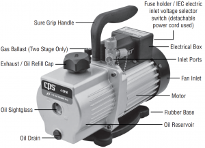
Unit consists of:
- Pro-Set ® model vacuum pump
- CPS® vacuum pump oil
- Operational manual.
6
VPC Series Parts
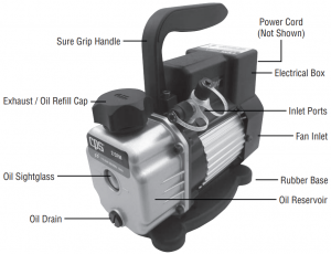
Unit consists of:
- Pro-Set ® model vacuum pump
- CPS® vacuum pump oil
- Operational manual.
7
Initial Preparation
- If the vacuum pump is equipped with a dual voltage motor, make sure the voltage selector switch is set for the desired voltage operation.
- The vacuum pump is shipped without oil in the reservoir. Remove the exhaust/oil fill cap and add oil until it is seen in the middle of the oil sight glass. Re-secure cap.
- Remove the 1/4″ inlet service port cap, turn on the vacuum pump. After 15 seconds, replace 1/4 cap back on inlet port.
- Re-check vacuum pump oil level. Add or remove oil if necessary.
To achieve good final vacuum levels, the oil level should be visually seen through sight glass.
CAUTION: DO NOT RUN THIS EQUIPMENT WITH LOW OR NO OIL. RUNNING THIS EQUIPMENT WITH NO LUBRICATION WILL CAUSE PREMATURE FAILURE.
VACUUM PUMP IS NOW READY FOR USE.
Vacuum Pump Operation
WARNING: Do not operate on systems under pressure.
- Check the correct power supply outlet to be used.
- The VP series is equipped with a dual voltage motor. Make sure the voltage selector switch is set for the desired voltage operation.
Caution: The motor will overheat and trip the thermal protector if the voltage selector and the power supply voltage do not match. - Connect the correct power cord from vacuum pump to power supply outlet.
- Check oil level in vacuum pump.
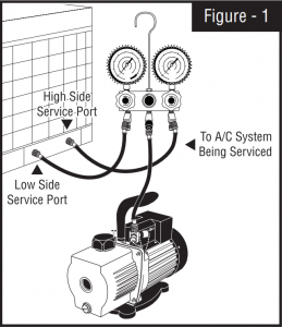
- Connect vacuum pump as shown in Figure – 1.
- Open manifold valves.
- Turn vacuum pump power switch “ON”.
- Run vacuum pump until final vacuum level is met.
- Once the final vacuum level is reached, close manifold valves, turn power switch “OFF”.
VACUUM OPERATION COMPLETE
Routine Maintenance
It is recommended to change the vacuum pump oil after 50 hours of usage. The purity of the oil will determine the final vacuum level achieved. Always use the CPS recommended vacuum pump oil (VPOQ / VPOP / VPOG). The oil provided with the pump has been specially blended to maintain maximum visosity at normal running temperatures as well as cold weather starts.
OIL CHANGE PROCEDURES:
- Be sure the pump oil is warmed up. if not warm, turn vacuum pump “ON” for 10 minutes.
- Make sure vacuum pump is not plugged in.
- Remove the oil drain cap and drain the contaminated oil into a suitable container. Tilt the vacuum pump toward the oil drain port.
- Once all the oil has been drained, re-secure the oil drain cap back onto the oil drain port.
- Remove the exhaust / oil fill cap and add oil until it is seen in the middle of the oil sight glass. Re-secure exhaust/oil fill cap.
9
Troubleshooting Chart
| Condition | Possible Problem | Solution |
| Unusually noisy | 1. Bad bearings.
2. Loose motor bolts. 3. Coupling drive. 4. Dirty, low, or improper oil. 5. Air leaks in connections. |
1. Replace motor.
2. Tighten bolts. 3. Adjust or replace coupling. 4. Replace oil. 5. Fix leaks. |
| High temperature | 1. Low or improper voltage.
2. Worn bearings. 3. Low oil level. |
1. Check power source voltage.
2. Replace motor. 3. Add or replace. |
| Poor vacuum | 1. System leaks.
2. Low oil level. 3. Dirty oil. 4. Air leaks at connection. 5. Air leak through seal. 6. Worn rotary mechanism. |
1. Fix leaks.
2. Add or replace oil. 3. Flush and replace oil. 4. Fix leaks. 5. Replace shaft seal. 6. Replace cartridge. |
| Oil leaks | 1. Oil leaks through exhaust.
2. Oil leaks through shaft seal. 3. Oil leaks through reservoir. 4. System vented pressure. 5. Pump tipped over. |
1. Oil level too high.
2. Replace shaft seal. 3. Tighten bolts or replace gasket. 4. Check oil level. 5. Check oil level. |
| Pump does not start | 1. No power to motor.
2. Damaged motor. 3. Thermal cutout. |
1. Check fuses in IEC panel.
2. Replace motor. 3. Wait for thermal switch to reset. Check for cause of thermal. |
| Thermal cutout | 1. Low or incorrect voltage.
2. Cold weather. 3. Dirty Oil. |
1. Check voltage, move voltage selector switch to correct setting.
2. Start and run vacuum pump with the intake fitting open for 1 minute to warm up oil. 3. Flush and replace oil. |
10
Learn more about automotive A/C tools and equipment we have.
]]>
[email protected]
www.neochair.com
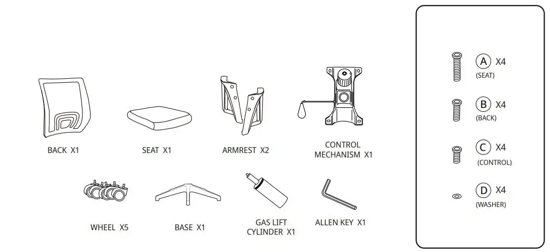
Please make sure all the parts are included.
Missing parts? [email protected]
Read the instructions carefully.

Please follow the assembly steps.

Instructions
NOTICE
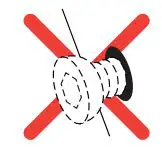
Please use the Allen key included instead of an electric drill.
TIPS!
Use the box for an easier assembly.
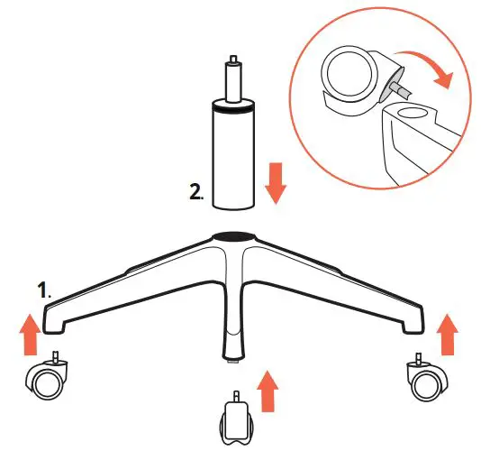
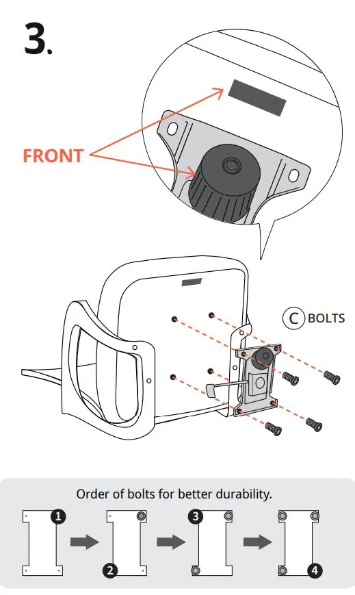
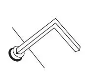
STEP 1 Bottom
![]() Use the base as support and press firmly from above with the wheel.
Use the base as support and press firmly from above with the wheel.
Make sure to put the wheels in the base before the gas lift cylinder.

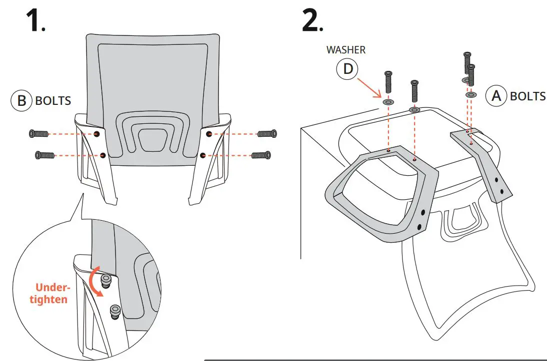
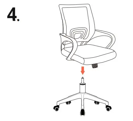
STEP 2 Top
If there are any problems, do not hesitate to e-mail us. [email protected]
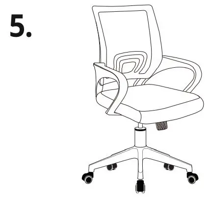
Done
User Manual
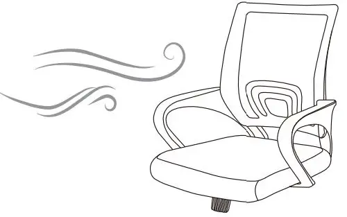
To deodorize your new chair
leave the chair in a shady outside for 1-2 days.
For longer use
Re-tighten bolts every 6 months by using the enclosed Allen-key.
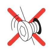
*Using an electric drill can damage the chair. Please re-tighten bolts manually.
Cautions

Use this product only for seating one person at a time

DO NOT use the chair unless all bolts, screws and knobs are tight
DO NOT use the chair if only components are missing or damaged
DO NOT stand on the chair use as a step stool or ladder

Regularly check all bolts, screws, and knobs are tight
Be careful, some of the part are heavy and has sharped edge

Failure to follow these warnings may cause serious injury
If there are any problems, do not hesitate to e-mail us. [email protected]
Enjoy your new favorite chair
Our goal is to create a perfect customer experience. Let us know if you have any feedback. Your comment motivates us to become a better team.
![]()


GENERAL INFORMATION
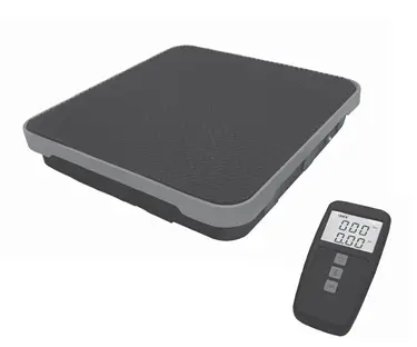
The CC240RF is an advanced, battery operated, WIRELESS weighing and charging scale. It has been designed to be accurate, rugged and reliable over a large weighing span (240 lbs / 110 kg). It incorporates a wireless display and control unit with 3 keys and an extra large LCD display for easy viewing. The scale platform incorporates a corner adjusted, heavy-duty load cell. 2.4 GHz wireless technology interconnects the display and control unit and the scale platform. This wireless scale system has a range of 30 feet (9m)
CC240RF Specifications
| CC240RF Specifications | |
| Working Load Capacity | 110 kg / 240 lbs |
| Overload Warning | 110 kg / 240 lbs |
| Operating Temperature | 14˚F to 122˚F or -10˚C to 50˚C |
| Operating and Storage Humidity | 0 to 95% non-condensing |
| Resolution | .25 oz (10 g) |
| Accuracy | +/- 0.05% of reading or +/- 0.25 (10 g) whichever is greater |
| Display & Control Unit Batteries | One 9V alkaline (ANSI 1604AC-IEC 6LR61) |
| Scale Platform Batteries | Four AA alkaline (ANSI 15A-IEC LR6) |
| Battery Life | 32 hrs. of continuous use |
| Battery Indicator | Battery symbol with 3 segment Power Level Bar Graph |
| Weight | 8 lbs 15 oz. (4.00 kg) with batteries |
| RF Frequency Range | 2.4 GHz, ISM band |
| RF Transmission Range | 30 feet (9m) |
| Warranty | 1 year |
Key Functions
NOTE: Every key press received by the scale platform is acknowledged with a beep. If you have lost connectivity, there will be no beep from the scale platform and the display may freeze. It will be necessary to re-enter the key stroke when you are within range and connectivity is restored.
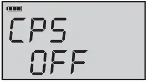
POWER [ ]: Turns the display and control unit as well as the weighing platform ON or OFF. Press once to turn power ON, if the display and control unit is OFF. To turn OFF press and hold until a beep is heard and CPS OFF appears on the screen
(See Fig. 11). This turns off both the scale platform and the display and control unit and also clears all memory and settings.
 Your body is an effective absorber of 2.4 GHz energy. DO NOT STAND
WITH YOUR BACK TO THE SCALE PLATFORM!
 Do not turn the display and control unit OFF if connection to the scale platform has been lost.
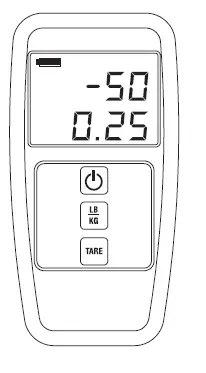
LB / KG (UNITS): Momentarily press to toggle units between Imperial and metric units.
TARE: Momentarily press to tare the weight on the platform. The weight display returns to zero.
Display Screens
The CC240RF can be used for weighing, charging and recovering refrigerants. The following are instructions on how to use the CC240RF for common refrigeration service functions.
You must be within 5 feet to initially connect to the scale. Range extends to 30 feet when connected. Turning the system ON and linking with the weighing platform:
Press the POWER [ ] key in the display and control unit. The following series of screens will appear as the display and control unit establishes communication with the weighing platform. A lot of useful information is displayed in the screens in the following figures.
OPERATION

Figure – 1: Displays the software version of the unit.
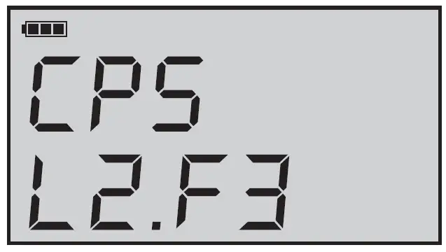
Figure – 2: Automatic Power Off enabled. Press [TARE] key to change. (See page 8 for details)

Figure – 3: Shows the display and control unit battery voltage.
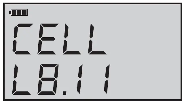
Figure – 4: Count down to connect with the scale platform on channel 0.
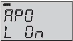
Figure – 5: Connection established. Displays software version of scale platform.
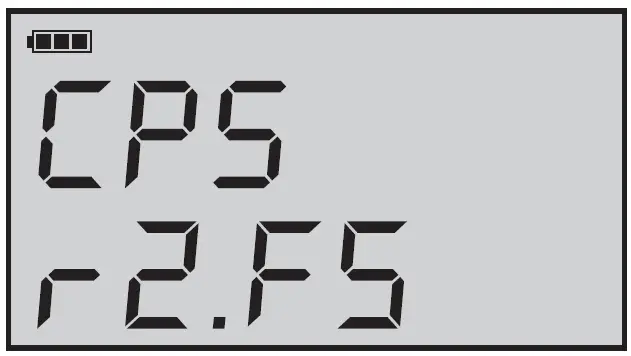
Figure – 6: Scale platform Automatic Power Off status.
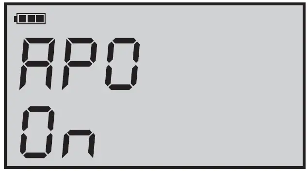
Figure – 7: Scale platform battery voltage.
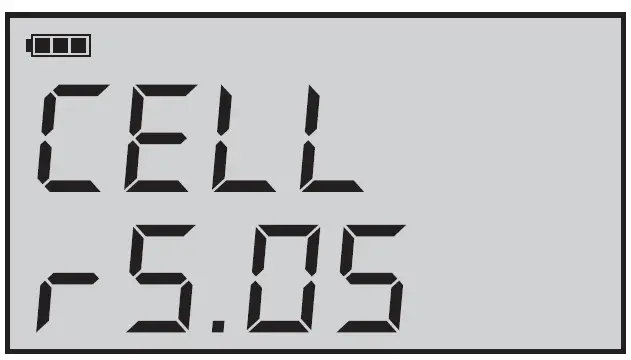
Figure – 8: Notifies the user that a zero calibration is being performed.

Figure – 9: Notifies the user that a full scale calibration is being performed.

Weigh Mode
- Place the weighing platform on a level, rigid surface.
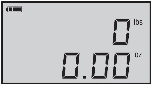
Figure – 11: Press and hold the POWER [ ] key until this message is displayed on the screen. - Press POWER [ ] key to turn the unit ON, any weight on platform will be set to zero. (See figures 1-10 for the screen squence while CC240RF turns on).
- Select the desired unit by pressing the [LB / KG] key.
- Place the object that is to be weighed on the platform.
- Gross weight will display.
- When weighing has been completed, press and hold the POWER key for 4 seconds to turn the unit OFF.
Charge Mode
- Place the weighing platform on a level, rigid surface.
- Press POWER [ ] key to turn the unit ON any weight on platform will be set to zero. (See figures
1-10 for the screen squence while CC240RF turns on).
- Select the desired units by pressing [LB / KG] key.
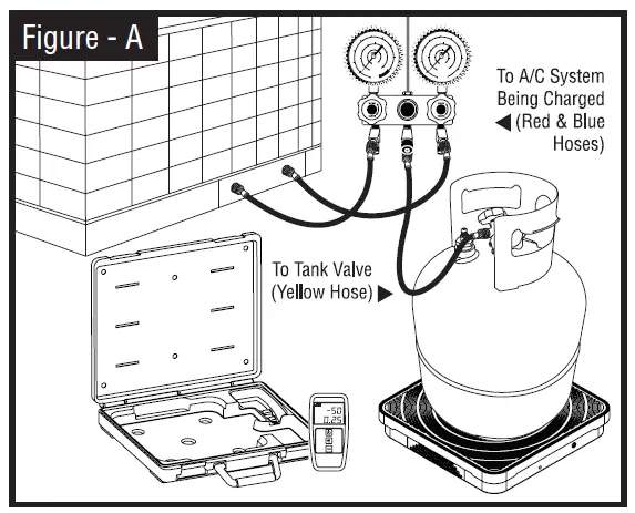
- Place cylinder on scale and connect scale as shown in Figure-A. The display will show the weight of the Freon® plus the weight of the cylinder. Press [TARE] to zero the scale platform.
- Open the cylinder valve and all other valves that are in the charging pathway.
- The display will show the amount of refrigerant leaving the tank.
- When the desired amount is reached, close the cylinder valve and the valves in the manifold.
- Press and hold the POWER [ ] key for 4 seconds to turn the unit off.
Recovery Mode
- Place the weighing platform on a level, rigid surface.
- Press POWER [ ] key to turn the unit ON any weight on platform will be set to zero. (See figures
1-10 for the screen squence while CC240RF turns on). - Select the desired units by pressing [LB / KG] key.
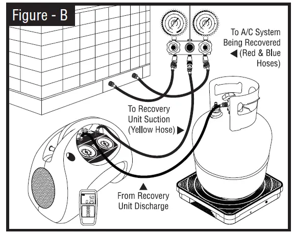
- Place cylinder on scale and connect scale as shown in Figure-B. Note the weight of the empty tank. Do not press [TARE] to zero the scale platform.
 When recovering refrigerant do not exceed the maximum tank fill weight. This weight equals the empty tank weight plus 80% of the water capacity
weight. The water capacity weight is usually stamped on the tank.

- Open the cylinder valve and all other valves that are in the recovery pathway. This allows the flow of refrigerant to the refrigerant recovery unit.
Danger – the recovery cylinder used contains liquid refrigerant. Overfilling of the recovery tank may cause a violent explosion resulting in severe injury or even death. - Turn on the refrigerant recovery unit. Follow the recovery unit’s instructions.
- If the recovery process finishes before the weight reaches the maximum tank fill weight, close the cylinder valve and all other valves that are in the recovery pathway. (Go to step #10)
- If the maximum tank fill weight is reached before the recovery process is finished, stop the recovery unit; close the cylinder valve and all other valves that are in the recovery pathway to the cylinder.
- Exchange the cylinder with an empty one and proceed back to STEP 4.
- When the recovery operation is completed, stop the recovery machine, close all the valves in the recovery pathway and press and hold the POWER [ ] key for 4 seconds to turn the unit OFF.
Additional Features
Battery Life Indications [  ] :
] :
The battery life remaining in the scale is shown on the LCD as a battery shape with 3 segment bar graph.
| 3 segments of Bar Graph | Battery at 100% to 80% |
| 2 segments of Bar Graph | Battery at 80% to 60% |
| 1 segment of Bar Graph | Battery at 60% to 20% |
| 0 segments of Bar Graph | Battery at 20% to 5%, recommend replace |
| LO CELL displayed on LCD | Battery below 5% |
Auto Tare and Overload Indicator Feature:
The unit will tare off any weight less than (240 lbs / 110 kg) while powering up. If the weight is more than its capacity, the unit will display “OL” to indicate overload. The “OL” will also display when the gross weight is more than its capacity.
For example: The unit starts with 230 pounds on its platform-display reads 0; placing 25 pounds makes the unit display OL.
Auto Shut Off Feature:
Auto Shut Off (APO) – The unit will automatically shut off after 10 minutes if the weight on its platform does not change by more than 1oz (40g) in that period of time. Pressing [TARE] key when the unit displays the message in Figure-2 toggles between APO ON and APO OFF.
 If the display and control unit is out of range of the scale platform and it turns off because of the APO, the scale platform will remain ON and subsequent connection will not be possible unless the batteries in the platform are removed and re-installed after a 60 second delay.
Troubleshooting
The CC240RF has been designed with the rough conditions of service work in mind. However, it is a precision instrument and, as such, certain precautions need to be observed to enjoy the benefits of its performance for a long time.
- Control and display unit does not turn on:
a. Check for dead batteries.
b. Check for reversed polarity.
c. Remove 9 volt alkaline battery for one minute; replace battery, listening for the battery installed tones.
The control and display unit will produce 2 beeps then 5 faster beeps. - Control and display unit fails to connect to scale platform:
a. Make sure you are within 5 feet (1.5 m.) of the scale platform.
b. Check for dead batteries in the scale platform.
c. Check the polarity of the batteries in the scale platform.
d. Use 4 fresh AA alkaline batteries. - Items 1 and 2 are satisfied but the control and display unit still fails to connect:
a. Place the control and display unit close to but
not on top of the scale platform then press
POWER [ ] key on the control and display
unit.
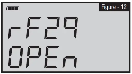
b. When the display gets to rf29 / CH x (See Fig.
4), press [TARE] the display will change to rf29/ OPEn (See Fig. 12).
c. When the control and display unit connects to the scale platform and the display enters the weighing mode, press and hold the POWER [ ] key and then press the [LB / KG] key and release both.
d. In addition to displaying the current channel, the display will compare 4 ID’s between the control and display unit and the scale platform.
e. The display will show the word “Good” in each case. If the ID’s do not match then a new application ID needs to be programmed. Please, contact the factory for instructions on how to do this.
Application ID:
The control and display unit and the scale platform are paired together at the factory. This feature allows the scale platform to communicate only with it’s paired control and display unit. Occasionally, is may be required to link the scale platform with a different control and display unit. Please, contact the factory for assistance with this function.
Install Batteries:
When the control and display unit is turned on, it will display the voltage of its battery (See Fig. 3). CPS recommends replacing the battery in the control and display unit with a fresh 9 V alkaline battery when the reading is 7.00 VDC, although useful operation can be obtained with battery voltages all the way to 6.00 VDC. During operation, the amount of battery life remaining will be displayed in the battery symbol on the display. When the battery is correctly installed, you will hear 2 tones followed by 5 faster tones. After the control and display unit connects with the scale platform, the voltage of the battery pack in the platform will be shown on the display (See Fig. 7). CPS recommends changing the scale platform batteries when the reading is 4.5 volts, although useful battery operation will result all the way down to 4.2 VDC; always use a set of 4 AA alkaline cells. When batteries are correctly installed, the scale platform will product a 7 tone musical tune.
 Note : For optimum performance, always replace both the HHLD and the Scale Platform batteries atthe same time. Ensure that you hear the appropriate tone, if not, remove, wait 1 minute and reinstall battery.
 Note : It is recommended that the HHLD and the Scale Platform be turned off prior to removing any batteries. Removing a battery when the Scale Platform is connected to the Hand Held, may cause the system to hang-up.Remove batteries from both devices if you feel you must remove a battery during operation.
Low Battery Indication:
If the system detects a low battery condition, the system will turn itself off in a safe condition. The display will show the word “CELL” and either “rxxx” or “Lxxx”. The “r” indicates the voltage of the scale platform batteries and “L” the voltage of the control and display unit battery voltage (See Fig. 3 & 7). The display then changes to “CPS Abrt” after a brief delay and then the system shuts off.
External Interference:
In the unlikely event that the CC240RF has difficulty maintaining connectivity or has numerous instances of the display freezing, no response to key entries, etc. the most probable cause is interference from other ISM band devices in the same channel. In that case, press and hold the POWER [ ] key and press the [TARE] key. To check that the channel has changed, press and hold the POWER [ ] key and then press the [LB / KG] key. The display will show all [4 id / Good] settings and then will show the new channel number and return to the normal weigh mode.
This instrument contains one or more
RF devices with FCC ID: X8BMT240, IC: 8826-MT240.
This product conforms to the applicable parts of FCC Rule 15.
SPECIFICATIONS
| Models | CR700/CR700JUK* | CR700E | CR700J | CR700S | |||||||
| Compressor Type | 1 HP Oil-less Reciprocating Compressor | ||||||||||
| Dimensions | 20cm (8”) wide x 37cm (14.5”) long x 30.5cm (12”) high | ||||||||||
| Weight | 15.3 kg (34 lbs.) | ||||||||||
| Operating Temperature Range | 0°C (32°F) to 49°C (120°) | ||||||||||
| Power Source | 115 V 50/60Hz 1 Ph | 220-240 V 50/60 Hz 1 Ph | 100 V 50/60 Hz 1 Ph | 230 V 50/60 Hz 1 Ph | |||||||
| Power Consumption | 850 W | ||||||||||
| Suction Pressure Gauge | -30” hg to 350 psig -76 cm hg to 35 kg/cm | -1 to 34.5 bar -100 kPa to 3450 kPa | -.1 to 3.5 MPa | -30” hg to 350 psig -76 cm hg to 35 kg/cm | |||||||
| Discharge Pressure Gauge | 0 to 800 psig 0 to 55 kg/cm |
0 to 55 bar 0 to 5500 kPa |
0 to 5.5 MPa | 0 to 800 psig 0 to 55 kg/cm |
|||||||
| Filtration | Cleanable 100-mesh screen integrated into Suction Port | ||||||||||
| Shut-Off Valves | Both Suction and Discharge piston manifold valves | ||||||||||
| Construction | Heavy gauge aluminum chassis with High Density Polyethylene Case | ||||||||||
| Overload Protection | 15 amp | 8 amp | 15 amp | 8 amp | |||||||
| High Pressure Shut-Off | 38 bar (550 psig) | ||||||||||
| Refrigerants | R-12, R-134a, R-401C, R-406A, R-500, R-401A R-409A, R-401B, R-412A, R-411A, R-407D, R-22 R-411B, R-502, R-407C, R-402B, R408A, R-509 R-407A, R-404A, R-402A, R-507, R-407B, R-410A |
||||||||||
| Flow Rate (at 60hz, reduce 15% for 50hz) Direct Vapor Direct Liquid Push-Pull Liquid |
Up to 43 kg/hr Up to 1.6 lb/min Up to 271 kg/hr Up to 10 lb/min Up to 542 kg/hr Up to 20 lb/min |
||||||||||
INTRODUCTION
Thank you for purchasing the CPS PROSET CR700 series unit. CPS is dedicated to give you the fastest and most reliable equipment to meet all your commercial refrigerant recovery requirements. In doing this CPS has integrated its latest technology and incorporated state of the art features while improving reliability and speed. The CR700 incorporates an Exclusive CPS Designed Patent Pending compressor that maximizes speed in both direct liquid and direct vapor recovery. The unit is equipped with a high airflow and high efficiency condensing system to maximize vapor recovery speed. The CR700 also incorporates an automatic Low
Pressure shut off switch.
The CR700 is designed for servicing commercial and residential refrigeration systems. Simply follow the quick start guide and turn it on. Once the recovery is complete, simply turn the center valve to the SELFCLEARING position. Now the unit is ready for the next type of refrigerant.
The PROSET CR700 series utilizes a 1 hp (0.85kW) patent pending oil-less compressor, non-restrictive piston manifold valves, and high capacity condensing system.
The following are additional features:
- “On the Run” SELF-CLEARING valve. No need to turn off the unit when switching from recovery to self-clearing.
- On board SUCTION and DISCHARGE gauges.
- 0 to 55 bar (800-psig) discharge gauge to handle R-410A.
- Small physical size.
- Automatic Low Pressure cutout switch.
- Integrated easy to use carrying handle and Safety bar.
- 550 psig High Pressure cutout switch
- Easy and secure filter accesses. No dangling filters to be damaged.
- Replaceable or cleanable filter cartridge.
- The Suction and Discharge shut-off valves. Easy to service if replacement required.
- Heavy-duty powder coated aluminum chassis surrounded by a tough High-Density Polyethylene case.
- Maintenance free Oil-less compressor
- Optional tank overfill sensor cord kit.
- patent pending
Low Pressure override switch to allow for continuous operation. To help you get a good start, please continue to carefully read the balance of this manual. This manual contains important information on the proper procedures for operating this equipment. Please pay close attention to the safety information, WARNING and CAUTIONS provided throughout this manual. Always remember “SAFETY FIRST”.
GENERAL SAFETY INSTRUCTIONS
Only qualified service personnel should operate this unit. Most states, countries, etc… may require the user to be licensed. Please check with your local government agency.
DANGER- the recovery tank used with this contains liquid refrigerant. Overfilling of the recovery tank may cause a violent explosion resulting in severe injury or even death. As a minimum, please use a scale to continuously monitor the recovery tank weight.
DANGER- Avoid breathing refrigerant vapors and lubricant vapor or mist. Breathing high concentration levels may cause heart arrhythmia, loss of consciousness, or even cause suffocation.
DANGER- ELECTRICAL SHOCK HAZARD-Always disconnect power source when servicing this equipment.
DANGER- EXPLOSION RISK. Do not recovery flammable refrigerants
CAUTION- all hoses may contain liquid refrigerant under pressure. Contact with refrigerant may cause frostbite or other related injuries. Wear proper personal protective equipment such as safety goggles and gloves. When disconnecting any hose, please use extreme caution.
CAUTION- avoid breathing refrigerant vapors and/or lubricant mist. Exposure may irritate eyes, nose, throat, and skin. Please read the manufacturers Material Safety Data Sheet for further safety information on refrigerants and lubricants.
CAUTION- to reduce the risk of fire, avoid the use of extension cords thinner than NO. 14 awg. (1,5mm) to prevent the overheating of this cord please keep length to a minimum.
CAUTION- do not use this equipment in the vicinity of spilled or open containers of gasoline or other flammable substances. Make certain that all safety devices are functioning properly before operating the equipment.
This equipment is intended for use of one refrigerant at a time until the Self Clearing feature is used. Mixing of different refrigerants will cause your recovered supply of refrigerant to become contaminated.
Note: It is very expensive to destroy mixed or damaged refrigerants

DIRECT LIQUID OR VAPOR OPERATION
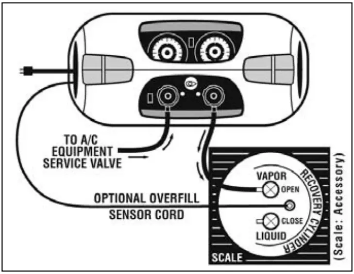
- Connect the unit as shown in Diagram 1.
Note: The recovery tank must be rated for 38 bar. - Open the vapor valve on the Recovery Tank.
- Open DISCHARGE valve on CR700.
Note: The Suction valve should be closed at this time. - Rotate the center valve to the “RECOVERY” position.
- Push the Main Power Switch “ON”.
Note: If the unit fails to start, make sure there is no suction pressure on the suction side of the unit. The compressor is designed to start against high differential pressures. Pressure on the suction side will reduce this differential. Reset Circuit Breaker if tripped. Push the LP Override Switch to the “ON” position. - Once unit has started, open the SUCTION valve on the CR700 to start the refrigerant flow.
- The CR700 is designed to directly recover large amounts of liquid refrigerant. If during liquid recovery the compressor begins to make a slugging or hammering noise, meter the incoming liquid by closing the suction valve until the noise subsides.
- The CR700 will automatically shut off* when a 10”hg vacuum is achieved. If the pressure rises (due to boiling liquid refrigerant) the CR700 will resume operation.
- After the CR700 has shut off, rotate the center valve to the SELF CLEARING position. The CR700 will resume operation automatically. The CR700 is now clearing out the condenser. The CR700 will automatically shut off* when a 10”hg vacuum is achieved.
Note: If the LP override switch is set to “ON” position the unit will run continuously.

RECOVERY AND SELF-CLEARING ARE COMPLETE
LIQUID PUSH-PULL OPERATION
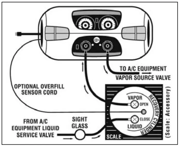
- Connect the unit as shown in Diagram 2.
Note: The recovery tank must be rated for 38 bar. - Open the liquid and vapor valve on the Recovery Tank.
Note: The Suction valve should be closed at this time. - Open the DISCHARGE valve on CR700.
- Rotate the center valve to the “SELF-CLEARING” position.
- Push the Main Power Switch “ON”
Note: If the unit fails to start, make sure there is no suction pressure on the suction side of the unit. The compressor is designed to start against high differential pressures. Pressure on the section side will reduce this differential. Reset Circuit Breaker if tripped. Push the LP Override Switch to the “ON” position. - Once unit has started, open the SUCTION valve on the CR700 to start the vapor refrigerant flow.
- Monitor the optional inline sight glass for liquid refrigerant movement.
- Once the liquid refrigerant is no longer present, close SUCTION valve. The CR700 will automatically shut off* when a 10”hg vacuum is achieved.
- Proceed to Direct Vapor Recovery Operation. (prior page)
Note: If the LP override switch is set to “ON” position the unit will run continuously.
ROUTINE MAINTENANCE
Filter Maintenance- the CR700 is equipped with a 100-mesh screen filter. This filter should be checked periodically. A partially clogged filter will slow down the recovery rate of this unit.
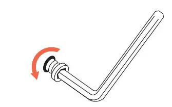
Check the filter cartridge as follows:
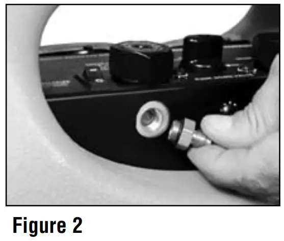
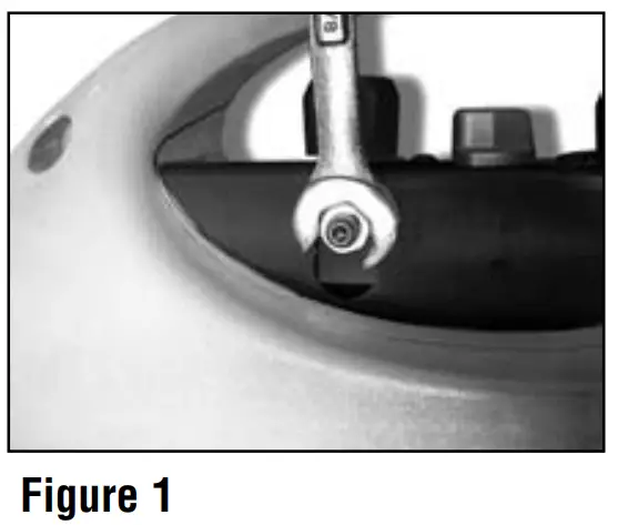
- Use a 5/8” socket or boxed end wrench to loosen the suction port as shown in Figure 1.
- Once loose, remove the suction port- filter cartridge as shown in Figure 2.
- Either clean the current cartridge or replace with new cartridge.
- Inspect O-ring. Re-lubricate with compressor oil or equivalent.
- Place filter cartridge back into suction port fitting.
- Hand tighten this assembly back onto the CR700.
- Use a 5/8” socket or boxed end wrench to tighten 1/8 of a turn.
Do not over tighten, damage to the O-ring may occur. - Check the connection for leaks.