DURACELL
1. Features
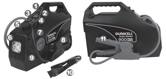
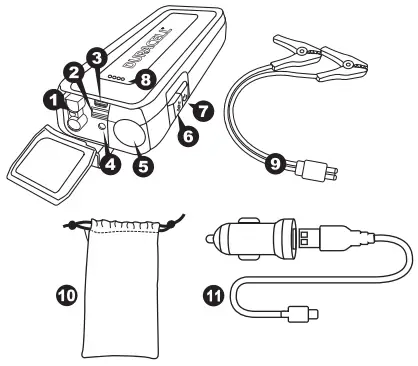
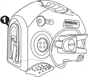
- Emergency light button.
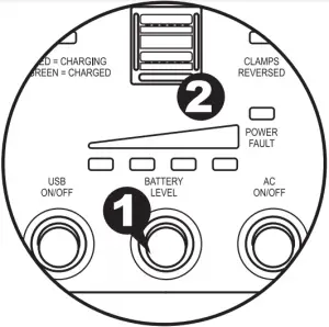
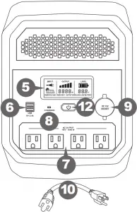
- Battery Level button and USB on/off switch turns on the battery level indicator. Turns on power to the USB charge port.
- LED fuel gauge. Battery level indicator shows battery fuel level.
- USB charge port. Supplies up to 2.1 Amps of charging power for your USB devices.
- 12V DC power socket powers 12V DC devices and appliances.
- Emergency light provides bright LED illumination in dark locations.
- Jump-starter ON/OFF switch
- Negative jump starting clamp connects to the negative battery terminal OR engine block (see Section 6)
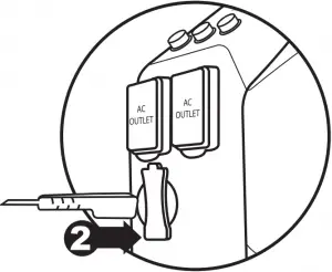
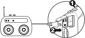
- AC battery charger port recharges the jump-starter’s internal battery from a standard AC wall outlet.
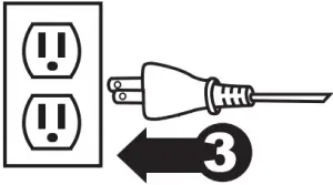
- AC power cord
- Positive jump starting clamp connects to the positive battery terminal (see Section 6)
2. Important Safety Information
Misusing or incorrectly connecting the Duracell® jump-starter may damage other equipment or create hazardous conditions for users.

WARNING: ELECTRICAL SHOCK HAZARD
The jump-starting clamps may spark if touched together. Always keep the clamps in their storage holsters when they are not being used.
3. Charging/Recharging the Jump-starter
![]()
Charge before first use
IMPORTANT
Prior to using the jump-starter for the first time, ensure that the battery of the jump-starter is fully charged. If the battery has been fully discharged, charging with the AC battery charger may take up to 12 hours.
![]()
Charging with the internal charger
Charging with the internal charger is a true “plug-in-and-forget” charging method. We recommend leaving the AC battery charger connected when the jump-starter is not in use.
- Disconnect any USB and 12V DC appliances from the DC power outlets.
- Insert the included AC cord end into the AC cord input port, then plug AC cord into a standard AC wall outlet.
- The charging LED shows the charging status.
- Recharging time should be approximately 12 hours if the jump-starter battery is fully discharged.
IMPORTANT
If you keep the jump-starter in storage, the battery will discharge over time. Remember to recharge the battery every three months to keep the jump-starter operational.
4. Checking the Jump-Starter’s Battery Level
To check the battery’s charge level, press the Battery Level button. The digital readout will display the approximate charge level.
Note: The level is approximate. You may see sudden small changes up to 20% when loads are applied or removed, this is only due to voltage changes and does not indicate sudden drops in charge state. It is recommended to maintain a full charge on the jump-starter at all times for optimal jump starting and device charging.
Note: Battery Fuel Gauge status is only accurate when the jump-starter has been disconnected from all appliances and all charging sources for 15 minutes.
5. Using the Jump-Starter’s Light / Power Ports
![]()
Using the built-in light
The Duracell® jump-starter has a built-in emergency light to provide a safe, bright work light on the roadside and in other outdoor environments.
- Push the “Emergency Light” button to turn on the LED light.
- When done, push the “Emergency Light” to turn the LED light off.
![]()
Using the USB port
The USB port provides up to 2.1 Amps of power to charge cell phones, smartphones, tablets and other devices.
To charge USB devices:
- Connect your USB device (smartphone, tablet etc.) to the USB port using the USB cable supplied with your device.
- Push the “Battery Level USB on/off” button.
- Charging will start and up to 2.1 Amps of current can be supplied by the port. The USB device controls the amount of current supplied.
- The USB port never “pushes” more current than required by the devices.
- Push the “Battery Level USB on/off” button again when done to turn the USB port off.
![]()
Using the 12V DC power socket
The jump-starter can operate 12V DC appliances that draw 11A or less.
CAUTION: EQUIPMENT DAMAGE
The DC power outlet does not automatically switch off when the internal battery is discharged. Check the battery status periodically to prevent total battery discharge.
To operate a 12V DC appliance:
- Open the protective cover on the jump-starter’s DC power socket.
- Plug the 12V DC appliance into the DC power outlet on the side of the unit, and turn the 12V DC appliance on (if required).
- Fully recharge the jump-starter as soon as possible after each use.
- As the DC power socket is internally wired directly to the jump-starter’s battery, extended operation of a 12V DC appliance may result in excessive battery discharge. See “Caution: Equipment Damage” above.
6. Jump-Starting A Vehicle’s Engine
You can use the Duracell® jump-starter with the supplied jump-start cables to jump-start a vehicle or boat engine that has a 12V starting battery.
WARNING: FIRE HAZARD
Never allow jump-start cables’ red and black clamps to touch each other or another common metal conductor. This could cause damage to the unit and/or create a sparking/ explosion hazard.
WARNING: FIRE HAZARD
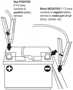
Jump-start cable clamps’ connection to the vehicle’s battery terminals must be positive to positive (red clamp to battery “+”) and negative to engine block. A reverse polarity connection (positive to negative) may cause damage to the unit and/or create a sparking/ explosion hazard.
WARNING: FIRE HAZARD
Do not crank the engine for more than 4 seconds. The jump-start feature is designed for short term operation only. Operating the jump-start feature for more than 4 seconds may cause damage to the unit. Allow the jump-starter to cool down for at least 30 seconds after each jump-start.
![]()
To jump-start a vehicle engine:
- Turn OFF the vehicle or boat ignition and all accessories.
- Engage the park or emergency brake and place the transmission in park for an automatic or neutral for a manual.
- If jump-starting a boat engine, purge the engine compartment and bilge of all fumes.
- Position the jump-starter on a flat, stable surface near the battery and away from all moving parts of the engine.
- Make sure the red jump-starter switch is in the OFF position then connect the red positive (+) clamp of the cables to the positive (+) terminal of the engine battery. The battery’s positive terminal is usually larger in diameter than the negative terminal. In most vehicles, the battery’s positive terminal has a red wire connected to it. (Refer to your vehicle’s owner manual).
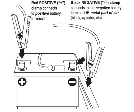
- Connect the black negative (–) clamp of the cables to the negative battery terminal, engine block, cylinder head, or other stationary heavy metal part of the motor.
- Correct polarity must be established before proceeding. Re-check your connections before starting your engine. If the clamps are reversed, an alarm will sound and “CLAMPS REVERSED” LED illuminate. Disconnect the jump-start clamps from the vehicle’s battery and redo steps 5 and 6 in this procedure.
- Before starting the engine, make sure the jump-starter and the cables are clear of belts and fans.
- Turn the jump-starter switch to the ON position and turn over the engine for 4 seconds or until it starts, whichever is first.
- Turn the jump-starter switch to the OFF position and remove the red positive (+) clamp and then the black negative (–) clamp from the vehicle.
- Store the jump-start clamps in the appropriate holder on each side of the jump-starter.
IMPORTANT
If you keep the jump-starter in storage, the battery will discharge over time. Remember to recharge the battery every three months to keep the jump-starter operational.
7. Maintenance
Routine maintenance is required to keep your Duracell® jump-starter operating properly. Occasionally clean the exterior of the unit with a damp cloth to remove the accumulated dust and dirt.
WARNING: SHOCK HAZARD
Disconnect all sources of AC power and DC power before performing any type of maintenance.
![]()
Battery maintenance
All rechargeable batteries gradually discharge when left standing, and you need to recharge them periodically to maintain maximum battery capacity. The charger within the jump-starter is designed to regulate the charging process, ensuring that the battery is always fully charged but never overcharged. To ensure safe recharging and maximum battery life, recharge the jump-starter only with the supplied charger or approved battery charger.
CAUTION
Due to inherent self-discharge, lead acid batteries must be charged at least every 3 months, especially in a warm environment. Leaving a battery in a discharged state, or not recharging every 3 months, may result in permanent battery damage and poor jumpstarting performance.
CAUTION
Do not attempt to recharge the jump-starter battery if it is frozen. Gradually warm the frozen battery to 32 °F (0 °C) before recharging.
8. Specifications
Electrical specifications
9. General Warnings and Cautions
IMPORTANT: Please read these general usage-related warnings and cautions thoroughly before using this jump-starter.
WARNING: Shock hazard. Keep away from children.
Do not insert foreign objects into the DC power socket, the USB port, or the ventilation holes. Do not expose this product to water, rain, snow, or spray. Do not open the unit. There are no user serviceable parts inside the unit.
CAUTION
Do not operate the jump-starter in temperatures under 0°C (32°F) or over 40°C (104°F).
WARNING: Explosion hazard
Do not use this product where there are flammable fumes or gases, such as in the bilge of a gasoline-powered boat, or near propane tanks. Use caution when using this product in an enclosure containing automotive-type lead-acid batteries. These batteries, unlike the sealed AGM battery in the Jump-starter, vent explosive hydrogen gas which can be ignited by sparks from electrical connections. When working on electrical equipment, always ensure someone is nearby to help you in an emergency.
WARNING: Proper application
Do not use the appliance for any application except that for which it is intended.
WARNING: Medical equipment
This product is NOT tested, designed nor intended to be used with life support systems or any other medical devices.
10. Recycling
Battery-Biz is committed to environmental responsibility and recommends that electronic devices be disposed of properly. Please contact your local city offices for information on recycling and disposal programs for e-waste.
For instructions on how to recycle this product visit http://www.call2recycle.org.
11. Contacting Customer Support
If you experience any problems or have any questions regarding your DURACELL® product, free technical support is available. Call from a phone where you have access to your mobile device.
Be prepared to provide the following information:
- Name, address and telephone number
- Name of the DURACELL® product
- Make and model of your device
- Symptoms of the problem(s) and what led to them
Technical Support is available by telephone:
U.S. and Canada (800) 300-1857
Outside of the US/Canada: (805) 437-7765
Written inquires should be directed to:
Battery-Biz Inc.
DURACELL® Product Inquiry
1380 Flynn Road, Camarillo, CA 93012, USA
WARNING
This product contains chemical(s) known to the State of California to cause cancer, birth defects, or other reproductive harm.
]]>
Owner’s Guide


WARNING: Electric shock and energy hazard
Do not remove cover. No user-serviceable parts inside. Refer servicing to qualified service personnel.
WARNING: Energy and burn hazard A battery can present a risk of burn from high short-circuit current.
CAUTION: Risk of damage to the PowerSource 1800
The unit will not work when connected to any AC load that has its neutral conductor connected to ground. Such loads include AC distribution wiring and house wiring.
FCC Information to the User
This equipment has been tested and found to comply with the limits for a Class B digital device, pursuant to part 15 of the FCC Rules. These limits are designed to provide reasonable protection against harmful interference in a residential installation. This equipment generates, uses and can radiate radio frequency energy and, if not installed and used in accordance with the instructions, may cause harmful interference to radio communications. However, there is no guarantee that interference will not occur in a particular installation. If this equipment does cause harmful interference to radio or television reception, which can be determined by turning the equipment off and on, the user is encouraged to try to correct the interference by one or more of the following measures:
- Reorient or relocate the receiving antenna.
- Increase the separation between the equipment and the receiver.
- Connect the equipment into an outlet on a circuit different from that to which the receiver is connected.
- Consult the dealer or an experienced radio/TV technician for help.
Guidelines for Use
Important: The PowerSource 1800 is not suitable for use with certain products and loads
The continuous output wattage of this product is limited to 1440 watts total when supplying backup power from its batteries. This limit applies to the total of all items plugged into the product.
This output wattage is not sufficient to run products designed to produce large amounts of heat, including space heaters and pellet stove igniters. Visit www.DuracellPower.com for higher power solutions.
Precautions for Using Rechargeable Appliances
CAUTION: Equipment Damage
When the PowerSource 1800 is supplying backup power from its batteries, its output is a non-sinusoidal modified sine wave, which is different from pure sine wave utility-supplied electricity. Certain types of load equipment may be damaged.
Most rechargeable battery-operated equipment uses a separate charger or transformer that is plugged into an AC receptacle and produces a low voltage charging output. Some chargers for rechargeable batteries can be damaged if connected to the PowerSource 1800.
Do not use the following with the PowerSource 1800:
- Small battery-operated appliances like flashlights, razors, and night lights that can be plugged directly into an AC receptacle to recharge.
- Some chargers for battery packs used in hand power tools. These chargers display a warning label stating that dangerous voltages are present at the battery terminals.
Note: If you are unsure about using your rechargeable appliance with the PowerSource 1800, contact the equipment manufacturer to determine the rechargeable appliance’s compatibility with the modified sine wave (non-sinusoidal) AC waveform.
Products with Potential Problems
Some products, including the types listed below, may be damaged if they are connected to the PowerSource 1800:
- Speed controllers found in some fans, power tools, kitchen appliances, garage door openers, and other loads may be damaged.
- Metal halide arc (MHI) lights can be damaged.
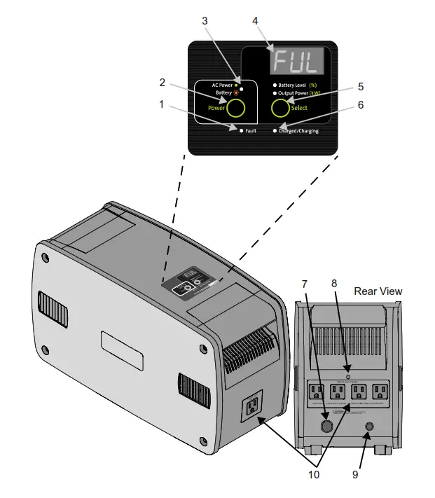
| Feature | Description |
| 1 | Fault LED illuminates red when PowerSource 1800 has an operation fault. |
| 2 | Power button turns PowerSource 1800 on and off when utility power is not available.
|
| 3 | AC Power/Battery LED illuminates green when utility power is available and flashes amber when PowerSource 1800 is running off its internal battery to provide backup power. |
| 4 | LED Screen indicates charging status, power draw from the PowerSource 1800 (W) when providing backup power, or battery capacity (%). The screen also shows error codes to aid troubleshooting. |
| 5 | Select Button displays PowerSource 1800 Battery Level (%) or Output Power (W). |
| 6 | Charged/Charging LED (green) illuminates when PowerSource 1800 is fully recharged and flashes while PowerSource 1800 is recharging. |
| 7 | AC Power Cord |
| 8 | Blue LED illuminates the rear AC outlets when AC power is available. |
| 9 | 15 A supplementary protector protects the PowerSource 1800 AC outlets and your applications from overload conditions. |
| 10 | Five 120V AC outlets (One in the front, four in the rear) for powering office equipment and household appliances that draw a maximum total of 1800 watts (1440 watts continuous). All outlets are surge protected and backed up by the PowerSource 1800 internal battery. |
Installation and Operation
WARNING: Shock Hazard
If the input plug is connected and utility power is present, the outlets will be energized. The front panel ON/OFF button will not turn these outlets off.
Important: PowerSource 1800 should be used or stored in a clean, temperature-controlled, indoor area away from direct sunlight, moisture or conductive contaminants. Allow a minimum of 3 inches of space around the unit for optimal ventilation.
Important: PowerSource 1800 must be charged immediately before storage or use. This will protect the battery inside from damage and will ensure extended usage run time. A complete charge may take up to 15 hours when recharged from a 120V AC wall outlet.
CAUTION: Equipment Damage
- Do not plug surge-protected power bars into the unit’s 120V AC outlets.
- Do not connect an AC power source to the 120V AC outlets.
- Do not connect the unit’s AC power cord to its 120V AC outlets.
To install PowerSource 1800:
- Plug the power cord directly into a wall outlet (not into a surge protector or power strip).
- Connect your electronic devices or small household appliances to the five AC outlets of the PowerSource 1800.
- Turn on the unit by pressing the Power button for at least half a second. The green AC Power LED confirms that the PowerSource 1800 is on and ready to provide backup power.
When the battery needs recharging, the LED screen flashes “CHG” 10 times, then the battery capacity (%) once. This pattern of flashing continues until the battery capacity reaches 100% and “FUL” appears on the screen.
Backup Power Feature
The unit’s five 120V AC outlets are permanently backed up by the internal battery when utility power is not available. To activate the AC outlets for backup operation, turn on the unit using the Power button. During a power outage or other utility problem (such as brownouts and over-voltages), PowerSource 1800 will keep running the connected products for up to 10 hours, depending on the power draw of your application (see “Run Time on Typical Products” and “Run-Time for Combinations of Products”). When utility power is restored, the unit automatically recharges its internal battery.
Important: When connected to utility power, the unit automatically provides AC power from its internal battery when the utility voltage falls below 105 V AC.
Operation Guide
| Condition | LED status | Alarm status | Alarm stops sounding when… |
| Normal operation: Utility power is available and unit is turned on. The internal battery is fully charged. | AC Power LED and Charged/Charging LED are solid green. Screen shows “FUL.” | None | Not applicable |
| Backup power: Utility power is not available. Unit supplies power from its internal battery. | Battery LED is flashing amber. | One beep when the power outage occurs. | Utility power becomes available; unit resumes normal operation or when it is turned off. |
| Low battery warning: During backup power operation, the internal battery is close to being completely discharged. | Battery LED is flashing amber. Screen shows Error code E05. | Beeps once every 2seconds. | Utility power becomes available; unit resumes normal operation or when it is turned off. |
| Overload shutdown: During backup power operation an AC outlet overload was detected. | Fault LED on. Screen shows Error code E03. | One beep per second. Unit shuts down after 10 seconds. | Not applicable |
| Under-voltage shutdown: During backup power operation, the battery power has been completely exhausted. No power is available at the AC outlets. | Fault LED on. Screen shows error code E01. | One beep per second. Unit shuts down after 10 seconds. | Not applicable. Unit starts recharging the internal battery when utility power is restored. Turn on the unit to restore normal operation. |
| Over-temperature warning: During backup power operation, the unit is close to shutting down to protect its internal circuitry from high temperatures. | Fault LED on. Screen shows error code E06. | Beeps once every 2 seconds. | Better ventilation to the unit is provided, or the unit enters over-temperature shutdown, or the unit is turned off. |
| Over-temperature shutdown: Unit has shut down to protect its internal circuitry from high temperatures. | Fault LED on. Screen shows error code E04. | One beep per second. | The unit is turned off or when the unit shuts down. |
| Recharging internal battery: Unit is recharging its internal battery after utility power has been restored. Internal fan is running. | AC Power LED is green. Charged/Charging LED flashes amber. Screen shows “CHG” alternating with battery capacity (%). |
No sound | Not applicable. Screen shows “FUL” when unit is completely charged. |
AC Power Capabilities
|
|
|
|
|
|
|
|
|
|
|
|
To check the total power consumption of the products plugged into PowerSource 1800 during backup power mode, press the Select button and view the Output Power (W) on the screen.
To test the PowerSource 1800 backup power capabilities after installing the unit, unplug the AC power cord to simulate a power outage. Ensure the products connected to the PowerSource 1800 continue operating. You can test the surge capabilities of the PowerSource 1800 by turning connected products on and off while the unit is unplugged. If products fail to operate or the screen shows an error code, see “Troubleshooting”.
Run Time on Typical Products
|
|
|
|
|
|
|
|
|
|
|
|
|
|
|
|
|
|
|
|
|
|
|
|
|
|
|
|
|
|
|
|
|
|
|
|
|
|
|
|
|
|
|
|
|
|
|
|
|
|
|
|
|
|
|
|
|
|
|
|
|
|
|
|
Run Time for Combinations of Products
| Product | Run Timeb |
| Laptop, inkjet printer, cordless phone, Internet modem | up to 10 h |
| Desktop computer, 17″ LCD monitor, inkjet printer, Internet modem, cordless phone | up to 1.6 h |
| Cordless phone, 13″ TV, clock radio, table lamp | Up to 4 h |
| 18 cubic foot refrigerator, home alarm system | Up to 2.6 h |
Power Management Tips
During a power outage, maximizing PowerSource 1800 run time is essential to keep your home/small office running or to stay connected to the outside world through TV and radio news or cellphone/cordless phone. Therefore, in order to maximize the run time for combinations of office products plugged into PowerSource 1800, you may want to use the following alternatives:
|
|
|
|
|
|
|
|
|
|
|
|
|
|
|
|
|
|
Recycling
If it’s rechargeable, it’s recyclable!
Battery-Biz is committed to environmental responsibility and has established a program for recycling Duracell rechargeable battery-related products.
For instructions on how to recycle this product visit www.rbrc.org
Troubleshooting
Understanding Error Codes
If the products connected to PowerSource 1800 do not operate and the alarm is sounding, check PowerSource 1800 LED screen for an error code.
| Error | Possible Cause | Solution |
| E01 | Low voltage shutdown because battery is discharged. | Recharge battery by plugging the AC power cord into a wall outlet. |
| E03 | Overload shutdown while supplying backup power. The AC product(s) connected are consuming more than PowerSource 1800’s power rating. The AC products connected have a surge power that exceeds PowerSource 1800 surge capability. One or more of the connected products are damaged. |
Use products with a total power consumption within PowerSource 1800’s continuous power rating of 1440 W. Use products with a total starting surge power within PowerSource 1800’s capability of 2880 W. Have the damaged product serviced by a qualified technician? |
| E04 | An over-temperature shutdown has occurred. PowerSource 1800 has overheated due to poor ventilation, excessive ambient temperature, or power demand beyond the unit’s output power capability. | Disconnect products from the AC outlets. Allow the unit to cool for 20 minutes. Clear blocked fan or remove objects covering unit. Move the unit to a cooler place. Reduce the load to less than 1800 W if continuous operation is required. |
| E05 | Under-voltage warning. The battery is nearly discharged. | Reduce the load to extend run time during backup mode. Assuming the AC power cord was unplugged and the unit turned to backup mode, when utility power is present or becomes available, recharge the battery by plugging the AC power cord into a wall outlet. |
| E06 | Over-temperature warning. PowerSource 1800 is overheating due to poor ventilation, excessive ambient temperature, or high power demand. | Reduce the load to avoid over-temperature shutdown, clear blocked fan or remove objects covering unit, or move the unit to a cooler place. |
Troubleshooting Reference
| Problem | Problem/Symptom | Solution |
| PowerSource 1800 will not turn on. | Battery is discharged and utility power is not available at the wall outlet. | Ensure power is available at the wall outlet. |
| No power available at the 120 VAC outlets. | AC outlet has been overloaded or the supplementary protector has tripped. | Reduce the number of products plugged into the AC outlets. Check the supplementary protector at the back of the unit. If necessary, reset the breaker by pushing it fully inward. |
| AC utility is not available and products connected to unit lose power. | PowerSource 1800 has detected an overload condition. PowerSource 1800 has detected an overtemperature condition. PowerSource 1800 has exhausted its available battery power. PowerSource 1800 may require service. |
Make sure the products plugged into the AC outlets are not exceeding the output power rating of the unit when supplying backup power. Try removing or substituting some of the products. Disconnect products from the AC outlets. Make sure the products plugged into the AC outlets are not overloading the continuous output power rating of the unit when supplying backup power. Allow the unit to cool, increasing ventilation if necessary. If the unit is left on, it restarts automatically when the unit cools down. PowerSource 1800 shuts down when all available battery power has been used. Allow the unit to recharge for 15 hours before continuing to use the unit. Contact Battery-Biz Technical Support for further troubleshooting (see “Contact Information” on page 1) |
| Products connected to unit malfunction or overheat. | Products connected to PowerSource 1800 do not accept modified sine waveform. | Your application is not compatible with PowerSource 1800 modified sine wave output. See “Precautions for Using Rechargeable Appliances” on page 2. |
| Inadequate run time. | PowerSource 1800 battery is not fully charged. Battery is near the end of its useful life. PowerSource 1800 has turned off. |
Charge the battery by leaving PowerSource 1800 plugged into a wall outlet at least 15 hours. As the battery ages, the available run time decreases. The internal battery also ages prematurely if PowerSource 1800 is installed in a hot environment or not kept in a charged condition. See “Battery Replacement” on page 5. Press for at least half a second to turn unit on. |
Specifications
Electrical Specifications
Output Specifications
| Continuous output power | 1440 W |
| Peak AC output power | 1800 W |
| Surge capacity | 2880 W |
| Output voltage (nominal) | 120 VAC |
| Output frequency | 60 Hz |
| Output waveform | Modified sine wave |
| Transfer switch | 15 A maximum/<80 milliseconds |
| Surge suppression | Yes |
| Inverter on (no-load current draw) | < 0.6 A (battery drain) |
| Charging time | 15 hours from 120 VAC |
12 V DC Specifications
| Internal battery type | Sealed lead acid, AGM |
| Internal battery capacity | 51 amp-hours (3 × 17 amp-hour batteries) |
| Internal battery voltage | 12 VDC (nominal) |
| Low battery alarm | 11.0 V (nominal) |
| Low battery shutdown | 10.5 V (nominal) |
| Internal charger charging current | 5 A DC maximum |
General Specifications
| Operating/Storage temperature | 32–86 °F (0–30 °C)/32–104 °F (0–40 °C) |
| Dimensions (H × W × L) | 19.25 × 8.25 × 11.25″ (48.9 × 21 × 28.6 cm) |
| Weight | 51.2 lb (23.2 kg) |
Approvals
ETL Certified to UL 1778 2nd Edition and CSA C22.2 no. 107.1-01 standby UPS Standards
FCC Class B
NOTE: All specifications are subject to change without notice.
Warranty
Quality Guarantee
Battery-Biz guarantees each Duracell® product to be free of defects due to faulty materials or workmanship. This Duracell® product carries a 1-year limited warranty from the date of purchase.
If found to be defective, this Duracell® product will be replaced without charge when returned to Battery-Biz. This guarantee does not apply to damage from misuse or abuse beyond normal usage. This guarantee gives you specific legal rights, and you may also have other rights which vary from state to state. Should any device be damaged by this product due to defects in the product arising from faulty materials or workmanship, Battery-Biz will repair or replace (at our option) the device, provided both device and product usage instructions have been followed.
Send device with the product to:
Battery-Biz Inc.
1380 Flynn Road, Camarillo, CA 93012
Attention: Duracell Product Returns
If you would like additional information on Duracell products call 1-800-842-2127 or 1-805-437-7765 (7:30 AM-4:30 PM PST).
Contacting Customer Support
If you experience any problems or have any questions regarding your DURACELL® product, free technical support is available. Prior to calling,
please review the technical support tips below.
- Call from a phone where you have access to your mobile device
- Be prepared to provide the following information:
– Name, address, and telephone number
– Name of the DURACELL® product
– Make and model of your device
– Symptoms of the problem(s) and what led to them
Technical Support is available by telephone
U.S. and Canada (800) 842-2127
Outside of the US/Canada: (805) 437-7765
Written inquires should be directed to:
Battery-Biz Inc.
DURACELL Product Inquiry
1380 Flynn Road,
Camarillo, CA 93012, USA
WARRANTY AND RETURN INFORMATION
One Year Limited Warranty
This product carries a limited warranty against defects in material and workmanship under normal use and service for one year from the original date of purchase. The manufacturer or distributor, at its option, shall repair or replace the defective unit covered by this warranty. Please retain the dated sales receipt as evidence of the date of purchase as it will be required for any warranty service. In order to keep the warranty in effect, the product must have been handled and used as described in the instructions accompanying this warranty. This warranty does not cover any damage due to accident, misuse, abuse, or negligence.
Disclaimer Of Warranty
The limited warranty described herein is your sole remedy. To the extent permitted by law, the manufacturer and distributor disclaim all other implied or express warranties including all warranties of merchantability and/or fitness for any particular purpose.
Limitation Of Liability
Except to the extent of repairing or replacing this product as expressly stated in
the limited warranty described herein, the manufacturer and distributor shall not
be liable for any damages, whether direct, indirect, incidental, special, consequential, exemplary, or otherwise, including lost revenues, lost profits, loss of
use of software, loss or recovery of data, rental of replacement equipment, downtime, damage to property, and third-party claims, arising out of any theory of recovery, including statutory, contract or tort. Notwithstanding the term of any limited or implied warranty, or in the event that any limited warranty fails of its essential purpose, in no event will the manufacturer’s and distributor’s entire liability exceed the purchase price of this product. Some states and provinces do not allow the exclusion or limitation of incidental or consequential damages so the above limitations or exclusions may not apply to you. This limited warranty gives you specific legal rights. You may have other rights which vary from state to state and province to province.
]]>DURACELL Lithium-Ion Jump Starter User Manual
1. Features
- Jump-start port connects to jump-start cable.
- USB port (2.4 Amps) charges smartphones, tablets and other devices.
- Charging port connects to USB cable to recharge the Jump-starter.
- LED status light Indicates state of the Jump-Starter connection (see Section 7).
- LED flashlight features steady beam and emergency strobe.
- Light button activates the LED flashlight.
- Power button displays battery level
- LED fuel gauge displays current Jump-starter battery level.
- Jump-start cable with Safejump™ feature.
- Carry bag fits into most vehicle glove boxes..
- DC charger and USB cable recharges the Jump-starter in the car or with your own AC wall charger (wall charger not included).
2. Important safety information
Misusing or incorrectly connecting the DURACELL® Jump-starter may damage the equipment or create hazardous conditions for users.
3. Charging the Jump-starter

WARNING: SHOCK HAZARD
Disconnect jump-start cables before charging the Jump-starter.
CAUTION
Do not attempt to recharge the Jump-starter battery if it is frozen. Gradually warm the frozen battery to 32 °F (0 °C) before recharging.
![]()
Charging before first use
IMPORTANT:
Prior to using the Jump-starter for the first time, ensure that the battery of the Jump-starter is fully charged. If the battery has been fully discharged, charging with a USB charger may take up to 4 hours.
![]()
Charging the Jump-Starter
Charging times: Partially discharged (or after using jump-starter) – 30-60 minutes; fully discharged jump-starter battery – up to 4 hours
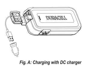
Charging with the included DC charger:
- Disconnect any cables from the Jump-starter and USB ports.
- Plug the DC charger into a 12V vehicle socket and connect your USB cable (not included) to the ‘IN’ port.
- It is best to have the vehicle started during charging.
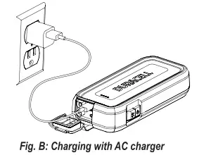
Charging with an AC charger (not included):
- Disconnect any cables from the Jump-starter and USB ports.
- Plug the USB cable (included) into your USB wall charger (not included).
- For safety we recommended using a certified USB wall charger bearing UL, TUV, CSA or ETL logo.
- Charging will only take 30 to 60 mins. after jump-starting or partial use. If completely empty a full re-charge may take up to 4 hours.
IMPORTANT
If you keep the Jump-starter in storage, the battery will discharge over time. Remember to recharge the battery after every use to make sure it is ready when you need it, and at least once a year. Re-charging more often will not harm the Jump-starter.
4. Checking the Jump-starter’s battery level
To check the battery’s charge level, press the power button on the Jump-starter. The LED lights will illuminate and display the current level of available battery power.
When all four lights are lit, this indicates that your Jump-starter is fully charged. It is recommended to maintain a full charge on the Jump-starter at all times for optimal jump starting and device charging.
IMPORTANT
Your Jump-starter will perform best when its battery Is fully charged. If the LED Fuel Gauge shows less than 100% charge, it is recommended to fully recharge your battery (see Section 3: “Charging the Jump-starter” above).
5. Using the LED Light / USB Port
![]() Using the LED light
Using the LED light
The DURACELL® Jump-starter has a built-in emergency light to provide a safe, bright work light on the roadside and in other outdoor environments.
- Press and release the LIGHT button – high mode
- Press and release the LIGHT button – low mode
- Press and release the LIGHT button – SOS mode
- Press and release – off
- Press and hold 3 seconds – off from any mode
![]()
Using the USB port
The USB port provides up to 2.4 Amps of current to charge cell phones, smartphones, tablets and other devices.
To charge USB devices:
- Open the protective cover over the USB port.
- Connect your USB device (smartphone, tablet, etc.) to the USB port using the USB cable supplied with your device.
- Press and release the POWER button.
- Charging will start and up to 2.4 Amps of current can be supplied by the port. The USB device controls the amount of current supplied. The Jump-starter never “pushes” more than required by the devices.
- When done, press and release the POWER button to turn the USB port off. If you remove the USB cable, the port will also turn off automatically after 30 seconds to conserve power.
6. Jump-starting a vehicle
You can use the DURACELL® Jump-starter with the supplied jump-start cable to jump-start a vehicle or boat engine that has a 12V starting battery.
WARNING: FIRE HAZARD
Do not crank the engine for more than 4 seconds. The jump-start feature is designed for short term operation only. Operating the jump-start feature for more than 4 seconds may cause damage to the unit. Allow the Jump-starter to cool down for at least 30 seconds after each jump-start.
![]()
To jump-start a vehicle engine:
- Turn OFF the vehicle or boat ignition and all accessories.
- Engage the park or emergency brake and place the transmission in park for an automatic or neutral for a manual.
- If jump-starting a boat engine, purge the engine compartment and bilge of all fumes.
- Position the jump-starter on a flat, stable surface near the battery and away from all moving parts of the engine. Make sure the battery terminals or other attachment points are clear of dirt and grease to allow proper electrical contact.
- Connect the red positive (+) clamp of the cables to the positive (+) terminal of the engine battery. The battery’s positive terminal is usually larger in diameter than the negative terminal. In most vehicles, the battery’s positive terminal has a red wire connected to it. (Refer to your vehicle’s owner manual).
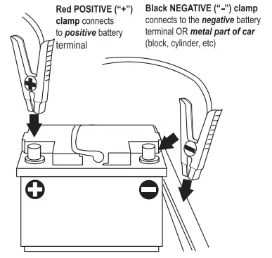
- Connect the black negative (-) clamp of the cables to the negative battery terminal, engine block, cylinder head, or other stationary heavy metal part of the motor.
- After a good connection the SafeJump™ feature will automatically verify polarity, voltage of vehicle and jump-starter, cell and circuit temperatures before displaying the green light to start the vehicle. See LED Status section for error conditions that may arise and corresponding suggestions.
- Before starting the engine, make sure the jump-starter and the cables are clear of belts and fans then crank for no more than 4 seconds each time with 30 seconds of rest in between starts.
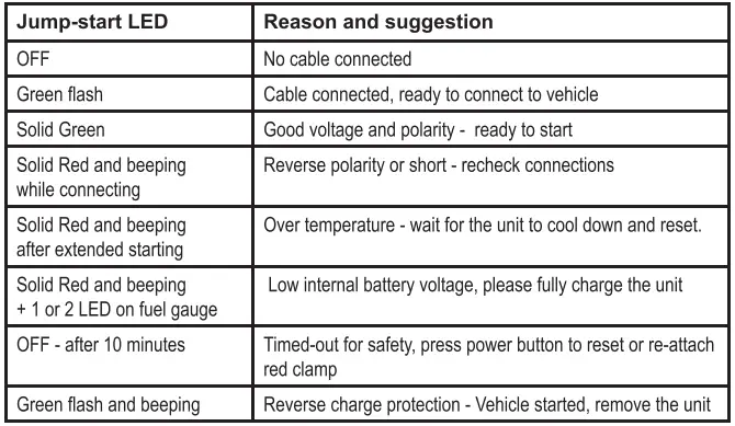
7. LED status light function
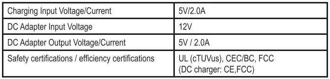
8. Specifications
Electrical specifications
Physical specifications

9. Important Safety Warnings
IMPORTANT: Please read these general usage-related warnings and cautions thoroughly before using this Jump-starter.
WARNING: When using this product, basic precautions should always be followed, including the following:
- Read all the instructions before using the product.
- To reduce the risk of injury, close supervision is necessary when product is used near children.
- Do not insert fingers or foreign objects into the product.
- Do not use this product with any application of which it was not intended.
- Use of an attachment no recommended or sold by the manufacturer may result in risk of fire, electric shock or injury.
WARNING: Medical equipment
This product is NOT tested, designed nor intended to be used with life support systems or any other medical devices.
WARNING: Proper application
Do not use the product if it is damaged or modified. Damaged or modified batteries may exhibit unpredictable behavior resulting in fire, explosion or risk of injury.
Do not operate the power pack with a damaged cord or plug.
Do not disassemble the power pack, contact the manufacturer when service or repair is required. Incorrect reassembly may result in a risk of fire.
WARNING: Risk of explosive gases
WORKING IN THE VICINITY OF A LEAD ACID BATTERY IS DANGEROUS. BATTERIES GENERATE EXPLOSIVE GASES DURING NORMAL BATTERY OPERATION. FOR THIS REASON, IT IS OF THE UTMOST IMPORTANCE THAT YOU FOLLOW THE INSTRUCTIONS EACH TIME YOU USE THE POWER PACK.
To reduce risk of vehicle battery explosion, follow these Instructions In vicinity of the battery. Review cautionary marking on this product and on vehicle engine
WARNING: Personal precautions
- Consider having someone close enough by to come to your aid when you work near a lead-acid battery.
- Have plenty of fresh water and soap nearby in case battery acid contacts skin, clothing, or eyes. o Wear complete eye protection and clothing protection. Avoid touching your eyes while working near a vehicle battery.
- If battery acid contacts skin or clothing, wash immediately with soap and water. If acid enters eye, Immediately flood eye with running cold water for at least 10 minutes and get medical attention Immediately.
- NEVER smoke or allow a spark or flame in vicinity of a vehicle battery or engine.
- Be extra cautious to reduce risk of dropping a metal tool onto the vehicle battery. It might spark or short-circuit battery or other electrical part that may cause an explosion.
- Remove personal metal items such as rings, bracelets, necklaces, and watches when working with a lead-acid battery. A lead-acid battery can produce a short-circuit current high enough to weld a ring or the like to metal, causing a severe burn.
- When charging the internal battery, work in a well ventilated area and do not restrict ventilation in any way.
- Under abusive conditions, liquid may be ejected from the battery, avoid any contact with this material. If contact accidentally occurs, flush with water. If liquid contacts eyes, additionally seek medical help. Liquid ejected from the battery may cause irritation or burns.
- Do not expose a power pack to fire or excessive temperature. Exposure to fire or temperature above 265°F (130°C) may cause an explosion.
- Attach output cables to a battery and chassis as indicated in these instructions. Never allow the output clamps to touch one another.
IMPORTANT: SAVE THESE INSTRUCTIONS
10. Recycling
DURACELL® is committed to environmental responsibility and recommends that electronic devices be disposed of properly. Please contact your local city offices for information on recycling and disposal programs for e-waste.
For instructions on how to recycle this product visit http://www.call2recycle.org.
11. Contacting Customer Support
If you experience any problems or have any questions regarding your DURACELL® product, free technical support is available. Prior to calling, please review the technical support tips below. Call from a phone where you have access to your mobile device
Be prepared to provide the following information:
- Name, address and telephone number
- Name of the DURACELL® product
- Make and model of your device
- Symptoms of the problem(s) and what led to them
Technical Support is available by telephone:
U.S. and Canada to 1-800-300-1857
Outside of the US/Canada: 1-805-437-7781
Written inquires should be directed to:
DURACELL® Product Inquiry
1380 Flynn Road, Camarillo, CA 93012, USA
Email inquires should be directed to:
WARNING
This product contains chemical(s) known to the State of California to cause cancer, birth defects, or other reproductive harm.
FCC Statement
This device complies with Part 15 of the FCC Rules. Operation of this product is subject to the following two conditions: (1) this device may not cause harmful interference, and (2) this device must accept any interference received, including interference that may cause undesired operation.
This equipment has been tested and found to comply within the limits for a class B digital device, pursuant to Part 15 of the FCC Rules. These limits are designed to provide reasonable protection against harmful interference in a residential installation. This equipment generates, uses, and can radiate radio frequency energy and, if not installed and used in accordance with the instructions, may cause harmful interference to radio communications. However, there is no guarantee that interference will not occur in a particular installation. If this equipment does cause harmful interference to radio or television reception, which can be determined by turning the equipment off and on, the user is encouraged to try to correct the interference by one or more of the following measures:
- Reorient or relocate the receiving antenna.
- Increase the separation between the equipment and receiver
- Connect the equipment into an outlet on a circuit different from that to which the receiver is connected.
- Consult the dealer or an experienced technician for help.
Changes or modifications not expressly approved by the party responsible for compliance with the FCC Rules could void the user’s authority to operate this equipment.
Canada ICES-003 Statement
This Class B digital apparatus complies with Canadian ICES-003.
- Under Industry Canada regulations, this radio transmitter may only operate using an antenna of a type and maximum (or lesser) gain approved for the transmitter by Industry Canada. To reduce potential radio interference to other users, the antenna type and its gain should be so chosen that the equivalent isotropic ally radiated power (e.i.r.p.) is not more than that necessary for successful communication.
- This equipment complies with IC radiation exposure limits set forth for an uncontrolled environment. This equipment should be installed and operated with minimum distance 20cm between the radiator and your body.
- “This device complies with Industry license-exempt RSS standard(s). Operation is subject to the following two conditions: (1) this device may not cause interference, and (2) this device must accept any interference, including interference that may cause undesired operation of the device.”
DURACELL
Powerpack Pro 1100/ Powerpack Pro 1300
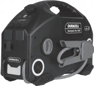
A. About the Powerpack Pro
The Duracell® Powerpack Pro is an ideal solution for jumpstarting cars, boats, or other vehicles. It also inflates tires, supplies portable AC, DC and USB power, and provides a bright work light. Its highly visible reflective trim serves as an additional night time safety feature.
The Duracell’ Powerpack Pro:
- Powers 115 V AC appliances
- Powers 12V DC appliances
- Powers 5 V USB devices
- Jurnissterts vehicle engines
- Provides lighting for emergency use
- Inflates vehicle tiros and small sports equipment
- Reflective urn provides high insibilsty at right
Comprehensive protection
Reverse polarity protection
The reverse polarity LEO will light up wren you connect the wrong terminals. The reverse polarity alarm will also beep.
Over current protection
The built in charger protects against over current when it is recharging.
Over voltage protection
The built in charger will shut off when the voltage reaches the limit.
B. What’s Included


1. Powerpack Pro 2. AC charging cord 3. Inflation accessories
1. Charging/recharging your Powerpack
 IMPORTANT – BEFORE YOU START
Please fully charge your Powerpack before using it for the first lime II is also recommended to fully recharge your Powerpack after each use.
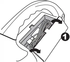
- Locate the AC charging cord stored in the compartment near the Powerpack’s handle.
- Plug the cord into the Powerpack’s AC charging input.
- Plug the other end of the cord into an AC wall outlet.
- Charging time is approximately 24 hours from a fully discharged battery to a full recharge. The Battery Status LED will turn green when fully charged.
- It is safe to leave the Powerpack plugged into an AC wall outlet so that it is always fully charged and ready when you need it. The charging current will automatically reduce to “maintenance” mode once the Powerpack has been fully charged.
Powerpack Charging: Important Notes
- Do not operate DC appliances with the Duracell® Powerpack Pro while the powerpack is being recharged with the AC cord. The AC cord may be permanently damaged if 12V DC appliances are operated while the AC cord is connected.
- If you keep the powerpack in storage, the battery will discharge over time. Remember to recharge the battery every three months to keep the powerpack operational.
- If the voltage in your wall outlet is less than 120V AC, it may take more than 24 hours to fully recharge the Powerpack. If, after 24 hours of charging, the Battery Status LED remains red, continue to charge the unit for another 12 hours. The unit will be ready for use even if the Battery Status LED remains red.
2. Checking the battery level
- Push the Battery Level button on the front panel.
- The LED gauge will display the current level of available battery power:
• Fully charged: All LEDs (one red, one yellow and two green) are illuminated when the battery is full.
• Completely discharged: Only the red LED is illuminated when the battery is completely empty.
Battery Level: Important Notes
Battery fuel gauge status is only accurate when the Powerpack has been disconnected from all appliances and all charging sources for 15 minutes.
3. Using the LED light
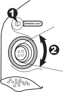
- Push the “Emergency Light” button to turn on the LED light.
- Gently swivel the lens up and down to aim the light beam.
- Push the “Emergency Light” button again to turn off the light.
4. Using the USB ports
The Powerpack’s dual USB ports can charge two USB devices at once, sup plying up to 2.4 total Amps of current.
- Connect your USB device (smartphone, tablet, etc.) to your own USB cable.
- Plug the USB cable into the Powerpack’s USB port.
- Push the “USB On/Off” button.
- Charging will begin. The Powerpack will adjust the amount of current supplied to each device based on its requirements.
- Push the “USB On/Off’ button again when done.

5. Using the AC outlets
The Powerpack’s dual AC outlets ports can power two AC appliances at once, up to a total of 240W for Powerpack Pro 1100, or 480W for Powerpack Pro
1300. For best results, ensure that your Powerpack is fully charged before using the AC outlets.
- Press the AC outlet ON/OFF Switch to the ON position.
- Open the protective cover on the AC power outlet and plug the AC appliance in.
- Fully recharge the Powerpack as soon as possible after each use.
- In the event of an overload, low battery voltage or overheating, the Powerpack automatically shuts down.
AC Appliances: Important Notes
Understanding appliance wattage
- AC appliances are rated by how much electrical power (in watts) they consume. The fewer watts an AC appliance uses, the longer the powerpack will operate before recharging is required.
- Some appliances may be difficult or impossible to operate from the Powerpack if they have a high surge rating or are not suitable for use with the Powerpack.
Trouble Appliances
To avoid damage to your AC appliance, the Powerpack is not recommended for use with the following:
- Electronics that modulate RF (radio frequency) signals on the AC line.
- Speed controllers found in some fans, power tools, kitchen appliances, and similar appliances.
- Some chargers for small rechargeable batteries can be damaged.
- Metal halide arc (MHI) lights can be damaged.
High Surge Appliances
“Surge” power is the initial amount of power required to start an appliance.
- Appliances such as televisions and appliances with motors consume much more power than their average (continuous use) rating when they are first switched on. This may exceed the capabilities of the Powerpack and trigger the safety overload shutdown circuit.
6. Using the 12V DC power outlet
The Powerpack can operate 12V DC appliances (such as those that plug into a vehicle’s lighter socket) that draw 20 Amps of power or less.
- Open the protective cover on the DC power outlet and plug your appliance into the port.
- Turn the appliance on (if required). The Powerpack will automatically supply power to your appliance.
- Fully recharge the Powerpack as soon as possible after use.

12V DC Outlet: Important Notes
Battery power drain
- As the DC power outlet is internally wired directly to the Powerpack’s battery, it does not automatically switch off. Check the battery status periodically to prevent total battery discharge.
- Extended operation of a 12V DC appliance may result in excessive battery discharge.
High-consumption DC appliances
- If your 12V DC appliance draws more than 20 Amps, the Powerpack’s internal circuit breaker shuts off the power to your appliance. You will not be able to use this appliance with the Powerpack. If shutoff occurs, unplug your appliance. The Powerpack’s internal circuit breaker automatically resets after a few seconds.
7. Jump-starting your vehicle
IMPORTANT – BEFORE YOU START
Please read these critical safety instructions carefully before jump-starting a car with the Powerpack.
Fire Safety
- Never allow jump-start cables’ red and black clamps to touch each other or another common metal conductor. This could damage the Powerpack and/or create a sparking/explosion hazard. Always switch OFF the Jump-Start power switch and store the jump-start clamps in the appropriate holder on each side of the Powerpack after use.
- Do not crank your vehicle’s engine for more than 4 seconds. The jump-start feature is designed for short term operation only. Operating the jump-start feature for more than 4 seconds may damage the Powerpack.
- Always allow the Powerpack to cool down for at least 3 minutes after each jump-start.
Personal Safety
- Always turn OFF the vehicle or boat ignition and all accessories.
- Engage the park or emergency brake and place the transmission in park for an automatic or neutral for a manual.
- If jump-starting a boat engine, purge the engine compartment and bilge of all fumes.
- Position the Duracell® Powerpack Pro on a flat, stable surface near the battery and away from all moving parts of the engine. Ensure that the jump-starting power switch is OFF.
Jump-starting your vehicle
- Remove the clamps from the holsters on each side of the Powerpack.
- Connect the red positive (+) clamp of the cables to the positive (+) terminal of the engine battery. The battery’s positive terminal is usually larger in diameter than the negative terminal. In most vehicles, the battery’s positive terminal has a red wire connected to it.
- Connect the black negative (-) clamp of the cables to the engine block, cylinder head, or other stationary heavy metal part of the motor.
4. If the “Clamps Reversed” LED illuminates, then reverse polarity has been detected. Disconnect the jump-start clamps from the vehicle’s battery and redo steps 1 and 2.
5. Switch ON the jump-starting power switch. Before starting the engine, make sure the Duracell® Powerpack Pro and the cables are clear of belts and fans.
6. Crank the engine for 4 seconds or until it starts, whichever is first.
8. Using the air compressor
IMPORTANT – BEFORE YOU START
Please read these critical safety instructions carefully before using the Powerpack’s air compressor.
Fire Safety
- The compressor is designed for short term operation only. Operating the compressor over an extended period of time will cause the compressor unit to overheat which could lead to fire.
- The powerpack cannot be used to inflate large capacity inflatables such as float tubes, large air mattresses, and inflatable boats. These types of products require extended inflating times that may damage the compressor.
- Always allow the compressor to cool down for 10 minutes after each 10 minutes of continuous operation.
Personal Safety
- Never leave the compressor unattended while in operation. Keep out of reach of children.
- The compressor is capable of inflating to 150 PSI. Do not exceed the recommended pressure of either the compressor or the object being inflated. If either recommended pressure is exceeded, an explosion may result.
- If the pressure gauge on the compressor indicates more than twice the recommended pressure for the object you are inflating, and you have only started to inflate the object, the valve connector is incorrectly connected to the valve stem. This may damage the Powerpack. Remove and reattach the valve connector to the valve stem.
Inflating tires (car, motorcycle, bicycle)
1. Remove the air compressor hose from the rear of the Powerpack.
2. Place the valve connector securely on the tire valve stem, push it as far as possible to allow normal airflow, and close the thumb latch. If necessary, use a supplied nozzle adapter.
3. Press the Air Compressor switch to turn the compressor on, and inflate your tire to its recommended pressure.

4. Switch the compressor off after appropriate pressure is reached.
5. Open the thumb latch and remove the valve connector from the valve stem.
6. Check the air pressure of the tire with a pressure gauge.
Inflating tires (car, motorcycle, bicycle)
- Place the valve connector fully on or into the valve receptacle on the item.
- Turn the compressor on and inflate to appropriate pressure.
You may also use a supplied nozzle adapter:
1. Locate proper nozzle adapter stored in the compartment near the Power pack’s handle.

2. Insert nozzle adapter into the valve receptacle of the item.
3. Turn the compressor off before removing nozzle adapter from valve stem.
4. Remove nozzle adapter from valve connector and return it to the storage compartment.
9. Connecting to an external battery
You can extend battery operating times by connecting the Powerpack to a larger external battery. For example, an external 54Ah battery gives approximately three times the operating time of the Powerpack’s own internal 18Ah or 15Ah battery.
IMPORTANT – BEFORE YOU START
Please read these critical safety instructions carefully before connecting the Powerpack to an external battery for the first time.
Fire Safety
- Never allow jump-start cables’ red and black clamps to touch each other or another common metal conductor. This could damage the Powerpack and/or create a sparking/explosion hazard.
- Jump-start cable clamps must be connected positive to positive (red clamp to battery “+”) and negative to negative (black clamp to battery “-“). A reverse polarity connection (positive to negative) may damage the Powerpack and/or create a sparking/explosion hazard.
Personal Safety
- Use a sealed, non-spillable external battery for indoor use. Common auto and marine batteries are not suitable for indoor use unless their fumes are vented outdoors. Common auto and marine batteries contain acid, which is hazardous if spilled.
- Wear eye protection and protective clothing when connecting the powerpack to an external battery.
To connect the Powerpack Pro to an external battery using the jump-start cables:
- Ensure that the jump-start power switch is OFF.
- Connect the red positive (+) clamp of the cables to the positive (+) terminal of the external battery.
- Connect the black negative (-) clamp of the cables to the negative (-) terminal of the external battery
- If the “Clamps Reversed” LED illuminates, then reverse polarity has been detected. Disconnect the jump-start clamps from the vehicle’s battery and redo steps 1 and 2.
- Disconnect the jump-start clamps from the battery and redo steps 2 and 3 in this procedure.
- Switch ON the jump-start power switch.
To disconnect:
7. Ensure that the jump-start power switch is OFF.
8. Remove the red positive (+) clamp, and then remove the black negative (-) clamp from the external battery terminals.
9. Store the jump-start clamps in the appropriate holder on each side of the Powerpack.
10. Recharge the powerpack as soon as possible after use.
10. Powerpack maintenance
Battery charging
All rechargeable batteries gradually discharge when left standing, and you need to recharge them periodically to maintain maximum battery capacity. The charger within the Powerpack is designed to regulate the charging process, ensuring that the battery is always fully charged but never
overcharged. To ensure safe recharging and maximum battery life, recharge the Powerpack only with the supplied charger.
Battery charging: Important notes
Please be sure to fully recharge your Powerpack every three months. This is important to maintain maximum life and usability of your Powerpack’s battery.
Leaving a battery in a discharged state may result in permanent battery damage and poor jump-starting performance.
Personal Safety
- Disconnect all sources of AC power and DC power before performing any type of maintenance to prevent accidental shock.
- Do not attempt to recharge the Duracell® Powerpack Pro battery if it is frozen. Gradually warm the frozen battery to 32 °F (0 °C) before recharging.
- Please see Section 1: “Charging/Recharging your Powerpack” for full instructions.
- Please also refer to Section 2: “Checking the battery level” for addi tional information.
- In addition to recharging the Powerpack’s battery, it is recommended to periodically clean the outside of the Powerpack with a damp cloth to remove the accumulated dust and dirt.
11. Recycling
If it’s rechargeable, it’s recyclable! Battery-Biz is committed to environmental responsibility and has established a program for recycling Duracel® rechargeable battery-related products.
For instructions on how to recycle this product visit http://www.call2recycle.org.
12. Troubleshooting
Below are some common problems that can occur with the Powerpack. If you cannot solve your problem, contact your dealer or Duracell Customer Service at (800) 842-2127.
Problem: AC appliance will not operate
Possible Cause : Solution
AC appliance rated more than 300 W (Powerpack Pro 1100) or 600 W (Powerpack Pro 1300): the safety overload has tripped.
Use an AC appliance with a lower power rating.
AC appliance is rated less than 300 W (Powerpack Pro 1100) or 600 W (Powerpack Pro 1300): high starting surge has tripped the safety overload.
AC appliance may exceed the Duracell® Powerpack Pro’s surge capability. Use an AC appliance with a starting surge within the Duracell® Powerpack surge rating.
Battery has discharged to 10.5 V.
Turn OFF the AC Power ON/OFF switch and recharge the Duracell® Powerpack.
Duracell® Powerpack Pro has overheated due to poor ventilation or excessively warm environmental conditions.
Turn the AC Power ON/OFF switch OFF and allow the Duracell® Powerpack Pro to cool for 15 minutes or more. Clear blocked openings or remove objects covering the unit, then restart the Duracell® Powerpack and move it to a cooler environment.
Problem: Overload shutdown.
Possible Cause : Solution
Appliance power requirements exceed the capability of the Duracell® Powerpack Pro.
Unplug the appliance and confirm that the appliance’s power requirement is 300 W (Powerpack Pro 1100) / 600 W (Powerpack Pro 1300) or less before attempting to restart the appliance.
Problem: Measured AC output voltage is too low.
Possible Cause : Solution
Using an average-reading AC voltmeter to read output voltage.
The modified sine wave output of the Duracell® Powerpack requires a true RMS reading meter, such as the Fluke 87 series, for accurate measurement.
Duracell® Powerpack Pro battery is almost fully discharged.
Press Battery Level button to verify battery status and recharge the Duracell® Powerpack Pro as necessary. Battery Level LEDs are only accurate when the unit has been disconnected from all appliances and all charging sources for 15 minutes.
Problem: Battery Status LED is red and has not changed to green after 24 hours of charging.
Possible Cause : Solution
The voltage at the AC wall outlet is less than 120VAC.
Use AC wall outlet that supplies 120VAC.
Continue to charge the unit for another 12 hours; the unit will be ready to use even if the Battery Status light remains red.
Problem: The engine being jump-started will not start.
Possible Cause : Solution
Duracell® Powerpack Pro battery is not fully charged.
Recharge the Duracell® Powerpack Pro battery.
The engine condition is poor.
Have the engine serviced.
The engine start capacity exceeds the Duracell® Powerpack Pro jump-start capability.
Use a higher power Duracell® Powerpack Pro.
Problem: The jump-start clamps measure zero volts.
Possible Cause : Solution
Jump-start power switch is OFF.
Turn the jump-start power switch ON.
Duracell® Powerpack Pro battery needs to be recharged.
Recharge the battery.
Problem: The compressor runs, but won’t inflate.
Possible Cause : Solution
The valve connector may not be securely placed on the valve stem.
Make sure the valve connector is securely placed on the valve stem before closing the thumb latch.
The item being inflated may have a leak.
Make sure the item being inflated doesn’t have a leak. Check the compressor hose for any breaks or leaks.
Problem: The compressor runs slowly.
Possible Cause : Solution
The compressor may have overheated from excessive use.
Turn off the compressor and let it cool down.
Battery voltage is too low.
Check the condition of the internal battery. The battery may need to be recharged or replaced.
13. User reference: Tire inflation
The information in the table below is for reference only. For precise pressure specifications, refer to the information supplied with the item to be inflated.
Type of tire Typical pressure specifica tions (PSI)
Automotive tires
520-13 26
A-78-14 26
E78-14 30
H-78-14 24
HR-78-15 28
Bicycle tires
27 x 1 1/4 85
20 x 1 1/2 40
Other Inflatables
Football 13
Basketball 9
Volleyball 5
Lawn tractor tire 22
14. Specifications
Important notes
All specifications are subject to change without notice.
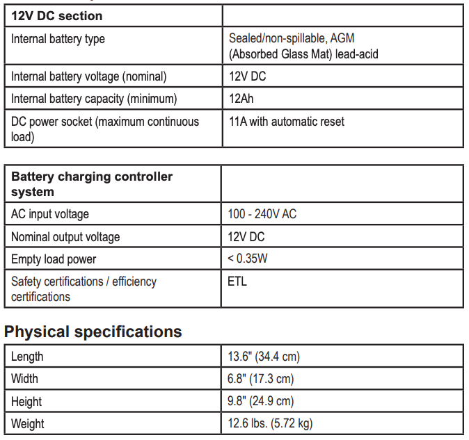
12V DC section
Internal battery type
Sealed/non-spillable, AGM (Absorbed Glass Mat) lead-acid
Internal battery voltage (nominal)
12V DC
Internal battery capacity (minimum)
DR300PWR……………………….. 12Ah
DR600PWR……………………….. 18Ah
DC power socket (maximum continu ous load)
20 A with automatic reset.
AC power section
Output power
• Continuous output power
DR300PWR……………240W
DR600PWR…………… 480W
• Output power (5 minutes)
DR300PWR……………. 300W
DR600PWR……………. 600W
• Peak AC output surge capacity
DR300PWR……………. 480W
DR600PWR……………. 750W
Output voltage 115V AC (RMS)
Output frequency 60Hz
Output wave form Modified sine wave
No load current draw <0.5 A DC
Input voltage range 10V to 15V DC
Low battery alarm 10.5V DC
Low battery shutdow 10.0V DC
High battery voltage shutdown 16V DC
Over temperature shutdown <194° F (90° C
Overload shutdow Yes, automatic reset
AC output short circuit protection Yes, automatic reset
Fuse (Internal)
DR300PWR…40Ax 1 (MAX),
DR600PWR…35Ax 2 (MAX)
Operating temperature range 32°-104 °F (0°-40 °C)
Storage temperature range 68°-122° F (-20° C –50°C)
Internal battery charging controller system
AC input voltage range 100-240V AC
AC input frequency 50/60Hz
Output voltage 15V DC
Rated voltage in floating charge 13.2Vdc@30mA
Empty load power < 0.5W
Safety standards ETL (for the charger)
Efficiency standards BC
Air compressor
Pressure 160 PSI (lb/in)
Physical specifications
Length 15.2 in. / 38.5 cm
Width 9.3 in. / 23.7 cm
Height 10.7 in. / 27.2 cm
Weight
DR300PWR………16.8 lbs. / 7.6 kg
DR600PWR………20.9 lbs. / 9.5 kg
Accessories
AC cord 52.4 in. (133cm)
Compressor nozzles Red air nozzle, blue air nozzle, inflator needle
15. Contacting Customer Support
If you experience any problems or have any questions regarding your DURACELL® product, free technical support is available. Prior to calling, please review the technical support tips below. Call from a phone where you have access to your mobile device.
Be prepared to provide the following information:
– Name, address and telephone number
– Name of the DURACELL® product – Make and model of your device
– Symptoms of the problem(s) and what led to them
Technical Support is available by telephone:
U.S. and Canada (800) 300-1857
Outside of the US/Canada: (805) 437-7765
Written inquires should be directed to:
Battery-Biz Inc.
DURACELL® Product Inquiry
1380 Flynn Road, Camarillo, CA93012, USA
16. Warranty and Return Information
Two Year Limited Warranty
The DURACELLP product carries a limited warranty against defects in material and workmanship under normal use and service for two years from the original date of purchase. The manufacturer or distributor, at its option, shall repair or replace the defective unit covered by this warranty. Please retain the dated sales receipt as evidence of the date of purchase as it will be required for any warranty service. In order to keep the warranty in effect, the product must have been handled and used as described in the instructions accompanying this warranty. This warranty does not cover any damage due to accident, misuse, abuse or negligence.
Disclaimer Of Warranty
The limited warranty described herein is your sole remedy. To the extent permitted by law, the manufacturer and distributor disclaim all other implied or express warranties including all warranties of merchantability and/or fitness for any particular purpose.
Limitation Of Liability
Except to the extent of repairing or replacing this product as expressly stated in the limited warranty described herein, the manufacturer and distributor shall not be liable for any damages, whether direct, indirect, incidental, special, consequential, exemplary, or otherwise, including lost revenues, lost profits, loss of use of software, loss or recovery of data, rental of replacement equipment, downtime, damage to property, and third-party of replacement equipment, downtime, damage to property, and third-party claims, arising out of any theory of recovery, including statutory, contract or tort. Not withstanding the term of any limited or implied warranty, or in the event that any limited warranty fails of its essential purpose, in no event will the manufacturer’s and distributors entire liability exceed the purchase price of this product. Some states and provinces do not allow the exclusion or limitation of incidental or consequential damages so the above limitations or exclusions may not apply to you. This limited warranty gives you specific legal rights. You may have other rights which vary from state to state and province to province.
WARNING
Pursuant to California Proposition 65, this product contains chemical(s) known to the State of California to cause cancer, birth defects, or other reproductive harm.
© 2016 Duracell. DURACELL’ is a registered trademark of Duracell, U.S. Operations, Inc., used under license. All rights reserved. All logos and trademarks are used for identification purposes only and may be trademarks or registered trademarks of their respective holders of their respective holders.
UM-DRPP300-600 Rev 20170111
]]>DURACELL® PowerSource 660 User Guide
Before You Start
 VERY IMPORTANT: CHARGE BEFORE USE
CHARGE BEFORE USE for at least 24 hours. For the life of the product keep it plugged in OR recharge every 3 months to prevent permanent battery damage.
IMPORTANT SAFETY INSTRUCTIONS
When using Duracell PowerSource 660, basic precautions should always be followed, including the following:
Operating the Duracell® PowerSource 660 incorrectly or misusing it may damage the equipment or create hazardous conditions for the user. See all WARNING statements below.
SAVE THESE INSTRUCTIONS-This manual contains important instructions. They need to be followed during installation and operation of this product.
Instructions Pertaining to Risk of Fire, Electric Shock or Injury to Persons
WARNING
When using this product, basic precautions should always be followed, including the following:
- Read all the instructions before using the product.
- Do not put fingers or hands into the product.
- Use of an attachment not recommended or sold by power pack manufacturer may result in a risk of fire, electric shock, or injury to persons.
- To reduce risk of damage to the electric plug and cord, pull the plug rather than the cord when disconnecting the power pack.
- Do not use a battery pack or appliance that is damaged or modified. Damaged or modified batteries may exhibit unpredictable behavior resulting in fire, explosion or risk of injury.
- Do not operate the power pack with a damaged cord or plug, or a damaged output cable.
- Do not disassemble the power pack, take it to a qualified service person when service or repair is required. Incorrect reassembly may result in a risk of fire or electric shock.
- To reduce the risk of electric shock, unplug the power pack form the outlet before attempting any instructed servicing.
WARNING: Risk of explosive gases
- WORKING IN VICINITY OF A LEAD ACID BATTERY IS DANGEROUS. BATTERIES GENERATE EXPLOSIVE GASES DURING NORMAL BATTERY OPERATION. FOR THIS REASON, IT IS OF THE UTMOST IMPORTANCE THAT YOU FOLLOW THE INSTRUCTIONS EACH TIME YOU USE THE POWER PACK.
- TO REDUCE RISK OF BATTERY EXPLOSION, FOLLOW THESE INSTRUCTIONS AND THOSE PUBLISHED BY BATTERY MANUFACTURER AND MANUFACTURER OF ANY EQUIPMENT YOU INTEND TO USE IN VICINITY OF THE BATTERY. REVIEW CAUTIONARY MARKING ON THESE PRODUCTS AND ON ENGINE.
PERSONAL PRECAUTION
- Consider having someone close enough by to come to your aid when you work near a lead-acid battery.
- Have plenty of fresh water and soap nearby in case battery acid contacts skin, clothing, or eyes.
- Wear complete eye protection and clothing protection. Avoid touching eyes while working near battery.
- If battery acid contacts skin or clothing, wash immediately with soap and water. If acid enters eye, immediately flood eye with running cold water for at least 10 minutes and get medical attention immediately.
- NEVER smoke or allow a spark or flame in vicinity of battery or engine.
- Be extra cautious to reduce risk of dropping a metal tool onto battery. It might spark or short-circuit battery or other electrical part that may cause explosion.
- Remove personal metal items such as rings, bracelets, necklaces, and watches when working with a lead-acid battery. A lead-acid battery can produce a short-circuit current high enough to weld a ring or the like to metal, causing a severe burn.
- When charging the intemal battery, work in a well ventilated area and do not restrict ventilation in any way.
- Under abusive conditions, liquid may be ejected from the battery; avoid contact. If contact accidentally occurs, flush with water. If liquid contacts eyes, additionally seek medical help. Liquid ejected from the battery may cause irritation or bums.
- Do not expose a power pack to fire or excessive temperature. Exposure to fire or temperature above 130°C may cause explosion. The temperature of 130°C can be replaced by the temperature of 265°F.
- Have servicing performed by a qualified repair person using only identical replacement parts. This will ensure that the safety of the product is maintained.
SAVE THESE INSTRUCTIONS
WARNING: Risk of injury or loss of life
Do not use this product in connection with life support systems or other medical equipment or devices.
Features
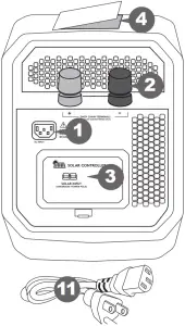
- AC input port: Use AC cord provided or UL approved extension cord.
- Daisy chain terminals: Connects to external 12V lead-acid batteries only
- Solar charge controller: Connects to 12V, 40-100W solar panel
- Storage tray: Holds AC input and output extension cords and user manual
- LED Screen: indicates charging status, power draw from the PowerSource when providing backup power, or battery capacity (%).
- USB ports: Provide up to 2.1A to charge USB devices.
- AC outlets: Provide up to 1440 Watts of household power. (4 outlets total).
- Charging LED:
• Flashes when charging
• Solid when charged - DC accessory socket: Powers 12V devices.
- Output extension cord: Extends the reach of the AC outlets for easier connection to your household electronics and appliances
- AC input cord: Plugs into the AC input port to power and charge the Powersource 660 from any wall outlet
- Power button: Turns the Powersource 660 unit on/off
Reading The LCD Display
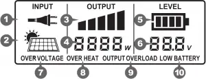
- AC Input: Input source is wail AC
- Solar input: Input source is solar panel (sold separately)
- Bar graph Watt meter: 5 bars is maximum rated continuous output
- Digital Watt meter: Displays output power in Wafts (W)
- Fuel gauge: Displays battery level
- Battery voltage
- Over voltage warning: Input over voltage
- Overheat: Inverter overheating; will shut down
- Output overload: Inverter overload; will shut down
- Low battery level: Internal battery low; please recharge the unit
Installation and Operation
WARNING: Shock hazard
If the input plug is connected and wall AC outlet power is present, the outlets will be energized.
IMPORTANT
The PowerSource 660 should be placed in a dry, well ventilated area with at least 6 inches of space in front and back of the unit for proper ventilation.
CAUTION: Equipment damage
- Do not plug surge-protected power bars into the units 115 VAC outlets.
- Do not connect an AC power source to the 115 VAC outlets.
Using the PowerSource 660
- Plug the AC input cord directly into a wall outlet (not into a surge protector or power strip). This will charge the unit and maintain the battery in optimal condition. You may leave it connected when not in use.
- Turn on the unit by pressing the power button for one second.

The LCD screen ,power inverter, USB ports and Instant-On UPS function will turn on. The LCD screen will dim after one minute to save power; a touch of the “Power Button” will restore the brightness.
Charging with a solar panel
- Use a 12V, 40-100W solar panel.
- The PowerSource 660 has a built-in solar charge controller. Do not use a panel with its own charge controller.
- Connect the solar panel to the solar controller input terminals.
- If the AC input is connected, the PowerSource will use the AC input instead of the solar input.
Backup Power Feature
The instant-on UPS function provides uninterrupted power to connected devices in the case of a power failure or other utility problems such as brownouts. Note: The unit must be ON for this function to work. See “Run Time on Typical Products” section for run times. When utility power is restored, the unit will automatically begin to recharge
AC Power Capabilities
Total power of devices : Operate on utility power? : Operate on backup power?
Up to 1440 W : Yes : Yes (up to 1440 W continuous in backup power mode)
Over 1440 W : No. supplementary protector may trip. : No. Overload shutdown.
To check the total power consumption of the products plugged into PowerSource 660 during backup power mode, press the Power button and view the Output Power (W) on the screen.
To test the PowerSource 660 backup power capabilities after installing the unit, unplug the AC power cord to simulate a power outage and ensure the products connected to the PowerSource 660 continue operating. You can test the surge capabilities of the PowerSource 660 by turning connected products on and off while the unit is unplugged. If products fail to operate or the screen shows an error message, see “Troubleshooting”.
Run Time on Typical Products(c)
Product Watts/VVatt-Hrs (a) Run Time (h) / Recharges(X)(b)
iPhone 8 7 Wh 60X
iPhone XR 11 Wh 40X
iPhone XS 10 Wh 40X
iPad Pro 11″ 29 Wh 14x
Laptop 90W, 55Wh battery 90 W 8X
LED string lights (50 lights) 3.5W 150 h
Speakers 60 W 8 h
Table lamp – LED bulb 7 W 70 h
32- LED/LCD TV 48 W 20 h
Desktop computer 150 W 3 h
8.8 cu. ft. freezer 80 W 7 h
Mini fridge 1.7 Cu ft 30 W 16 h
Sump pump ‘A HP 300W 1.5h
Microwave 900 W 0.5 h
- (a) Average power consumption as measured on loads tested under regular operating conditions. Rated power may differ from average power consumption.
- (b) Run time as measured on tested loads.
- (c) If you plug in devices that have a high power requirement (a large refrigerator), the charge level can drop very quickly and you may not obtain all the capacity; if you’re recharging devices that draw lower power (30W) you will get closer to the rated capacity.
GUIDELINES FOR USE
Important: The PowerSource 660 is not suitable for use with certain products and loads. The continuous output wattage of this product is limited to 1440 watts total when supplying backup power from its batteries. This limit applies to the total of all items plugged into the product.
This output wattage is not sufficient to run products designed to produce large amounts of heat, including space heaters and pellet stove igniters.
PRECAUTIONS FOR USING RECHARGEABLE APPLIANCES
CAUTION: Equipment damage
When the PowerSource 660 is supplying backup power from its battery, its output is a non-sinusoidal modified sine wave, which is different from pure sine wave utility-supplied electricity. Certain types of load equipment may be damaged.
Most rechargeable battery-operated equipment uses a separate charger or transformer that is plugged into an AC receptacle and produces a low voltage charging output. Some chargers for rechargeable batteries can be damaged if connected to the PowerSource 660.
Do not use the following with the PowerSource 660:
- Small battery-operated appliances like flashlights, razors and night lights that can be plugged directly into an AC receptacle to recharge.
- Some chargers for battery packs used in hand power tools. These chargers display a warning label stating that dangerous voltages are present at the battery terminals.
NOTE:
If you are unsure about using your rechargeable appliance with the PowerSource 660, contact the equipment manufacturer to determine the rechargeable appliance’s compatibility with the modified sine wave (non-sinusoidal) AC wave form.
PRODUCTS WITH POTENTIAL PROBLEMS
Some products, including the types listed below, may be damaged if they are connected to the PowerSource 660:
- Speed controllers found in some fans, power tools, kitchen appliances, garage door openers, and other loads may be damaged.
- Metal halide arc (MHI) lights can be damaged.
CAUTION: GROUNDING INSTRUCTIONS
This product must be grounded. If it should malfunction or breakdown, grounding provides a path of least resistance for electric current to reduce the risk of electric shock. This product is equipped with a cord having an equipment grounding conductor and a grounding plug. The plug must be plugged into an outlet that is properly installed and grounded in accordance with all local codes ordinances.
WARNING — Improper connection of the equipment grounding conductor is able to result in a risk of electric shock. Check with a qualified electrician if you are in doubt as to whether the product is properly grounded. Do not modify the plug provided with the product — if it will not fit the outlet, have a proper outlet installed by a qualified electrician.
Caution: Floating Grounding. Ground is floating when AC input cord is not connect to a wall outlet.
Power Management Tips
During a power outage, maximizing PowerSource 660 run time is essential to keep your home/small office running or to stay connected to the outside world through a TV, radio or phones. Therefore, in order to maximize the run time for combinations of office products plugged into PowerSource 660, you may want to use the following altematives:
Use… Instead of…
Inkjet printer Laser printer
Laptop, or desktop computer with LCD monitor Desktop computer with CRT monitor
Monitor energy saving mode settings Bright monitor settings
21 or 32″ LCD/LED TVs Big screen TVs
LED lamps Incandescent lamps
Attaching An External Battery (Extending the PowerSource 660’s Battery Capacity)
You can extend the run time for your devices by attaching an external 12V battery in parallel using the Daisy-chain terminal (see Features). To attach an external battery you will need to purchase battery cables with ring terminals. We recommend 2AWG cables, 3 ft. long. If a permanent installation is required we recommend using a 200A in-line fuse.
Replacing the PowerSource 660’s Internal Battery
CAUTION: Shock hazard
Before attempting to replace the battery, please consult with an electrician or mechanic.
- Remove the 6 hex head screws.
- Pull lid off.
- Use ratchet tool with a 10mm socket to disassemble battery cables. *Note: Make sure to not lose or drop washers which are located on both sides of the battery cables. Once cables are loose, place the cables out of the way to avoid any shock hazards.
- Use ratchet tool with a 13mm socket to remove the battery brace. *Note: Make sure to not lose or drop washers when removing brace.
- Carefully lift the battery. *CAUTION: Battery is heavy!
- Place new battery into the DR660PSS. *Note: Please see Specifications for battery compatibility.
- Re-attach the battery brace.
- Re-attach the battery cables onto your new battery.
- Place the lid back onto the DR660PSS.
- Screw the 6 hex head screws to secure the lid onto the DR660PSS.
Operation Guide
Operation LCD Display Notes
Charging from wall: Plugged into wall AC outlet, PowerSource 660 is off and battery is charging LCD screen is blank.
- LCD: Off
- Charge LED: Blinking when charging and solid when charged
Charging, UPS ready: Plugged in wall AC outlet, PowerSource 660 is ON and ready to provide instant backup power. 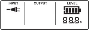 •
•
- LCD: On
- INPUT: AC cord icon
- OUTPUT: Blank, power is passing from AC wall source, inverter is not providing power.
- LEVEL: Battery level and Battery voltage is displayed
Backup Power: After power outage the PowerSource 660 instantly provides power to connected devices 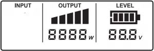
- INPUT: Blank, there is no input from the wall
- OUTPUT: Displays output graph and output wattage supplied by Inverter
- LEVEL: Shows battery level and battery voltage – Battery level is voltage based so you may see sudden changes in Battery Level and Voltage when loads chnage.
Charging from Solar source only, PowerSource 660 OFF: Solar panel connected, Wall AC not connected LCD screen is blank.
- LCD: Off
- Charge LED: Blinking when charging and solid when charged
Charging from Solar source only, PowerSource 660 ON: Solar panel connected, Wall AC not connected, PowerSource 660 ON 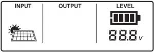
- LCD: On
- INPUT: solar icon
- OUTPUT: Blank
- LEVEL: Battery level and Battery voltage is displayed.
Low battery warning: Battery is almost empty. 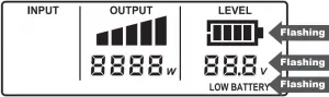
- OUTPUT: Shows power draw
- LEVEL: Flashing battery level and voltage (10.5V +- .5V)
- WARNING: “LOW BATTERY” warning is flashing with beeping sound
Low battery shutdown: Battery is empty. LCD screen is off (unit is shut down) At (9.5V +- .5V) LCD and Inverter turns OFF to protect the battery from over-discharge.
Overload: Excessive Inverter load 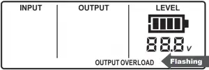
- OUTPUT: Blank; the Inverter has shut down.
- LEVEL: Shows current battery level and voltage
- WARNING: ‘OUTPUT OVERLOAD” Warning flashes with beeping sound.
- REMEDY: Check wattage of connected devices to make sure they do not exceed the rated output of 1440W Higher wattage loads will run for short periods until the overload or over heat protection.
Over Heat: Inverter temperature exceed due to poor ventilation or excessive load
- OUTPUT: Blank, the Inverter has shutdown.
- LEVEL: Shows current battery level and voltage
- WARNING:”OVER HEAT” Warning flashes with beeping sound
- REMEDY: Check ventilation openings, surrounding area and room temperature toensure proper airflow.
Over Voltage: The battery voltage is excessively high 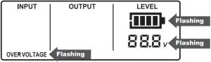
- LEVEL: Flashing battery level and voltage (16V +- .5V)
- WARNING: “OVER VOLTAGE” warning is flashing with beeping sound
- REMEDY. The inverter protects itself from high voltages by shutting down. Higher voltage external batteries or chargers can raise the battery voltage. Check external inputs.
Specifications
Electrical Specifications
Output Specifications
Continuous output power 1440 W
Surge power (momentary) 2880 W
Output voltage (nominal) 115 VAC ± 10%
Output frequency 60 Hz
Output wave form Modified sine wave
UPS Transfer time 5. 20 millisecond
Surge suppression Yes
Inverter on (no-load current draw) < 0.8 A (battery drain)
Charging time 24 hours for an empty battery
DC Specifications
Internal battery type Sealed lead acid
Internal battery capacity 55 Amp-Hour (660 Watt-Hour)
Internal battery voltage 12 VDC (nominal)
Low battery alarm 10.5 (+1- 0.5) VDC
Low battery shutdown 9.5 (+/- 0.5) VDC
Charging current (built-in charger) 6 ADC maximum
Accessory socket 12VDC (nominal), 20A
USB Ports 2 ports: 5V, 2.1A each
Solar Charge Controller Specifications
Solar panel compatibility 12V nominal, open circuit voltage <= 20V, wattage <=100W
Solar controller type PWM
Solar connector Anderson Powerpole PP15-45
Protections Reverse connection, short-circuit, reverse charging, under voltage
General Specifications
Operating/Storage temperature 32° to 104° F (0° to 40° C)/ -4° to 104° F (-20° to 50° C)
Dimensions (L x W x H) 19.9 x 8.9 x 12.8″ (50.5 x 22.6 x 32.4 cm)
Weight 56.2 lb (25.5 kg)
Approvals UL2743
FCC part 15
BC (CEC)
DOE
NOTE: All specifications are subject to change without notice
Recycling
Battery-Biz is committed to environmental responsibility and recommends that electronic devices be disposed of property. Please contact your local city offices for information on recycling and disposal programs for e-waste.
For instructions on how to recycle this product visit http://www.call2recycle.org.
Contacting Customer Support
If you experience any problems or have any questions regarding your DURACELL& product, free technical support is available. Prior to calling, please review the technical support tips below.
Call from a phone where you have access to your mobile device
Be prepared to provide the following information:
– Name, address and telephone number
– Name of the DURACELL& product
– Make and model of your device
– Symptoms of the problem(s) and what led to them
– Proof of Purchase
Technical Support is available by telephone:
U.S. and Canada (800) 300-1857
Outside of the US/Canada: (805) 437-7765
Written inquires should be directed to:
Battery-Biz Inc.
DURACELL& Product Inquiry
1380 Flynn Road, Camarillo, CA 93012, USA
Email Inquiries should be sent to our customer service email: [email protected]
Warranty And Returns
Two Year Limited Warranty
The DURACELL® product carries a limited warranty against defects in material and workmanship under normal use and service for two years from the original date of purchase. The manufacturer or distributor, at its option, shall repair or replace the defective unit covered by this warranty. Please retain the dated sales receipt as evidence of the date of purchase as it will be required for any warranty service. In order to keep the warranty in effect, the product must have been handled and used as described in the instructions accompanying this warranty. This warranty does not cover any damage due to accident, misuse, abuse or negligence.
Disclaimer Of Warranty
The limited warranty described herein is your sole remedy. To the extent permitted by law, the manufacturer and distributor disclaim all other implied or express warranties including all warranties of merchantability and/or fitness for any particular purpose.
Limitation Of Liability
Except to the extent of repairing or replacing this product as expressly stated in the limited warranty described herein, the manufacturer and distributor shall not be liable for any damages, whether direct, indirect, incidental, special, consequential, exemplary, or otherwise, including lost revenues, lost profits, loss of use of software, loss or recovery of data, rental of replacement equipment, downtime, damage to property, and third-party claims, arising out of any theory of recovery, including statutory, contract or tort. Not withstanding the term of any limited or implied warranty, or in the event that any limited warranty fails of its essential purpose, in no event will the manufacturer’s any limited or implied warranty, or in the event that any limited warranty fails of its essential purpose, in no event will the manufacturer’s and distributors entire liability exceed the purchase price of this product. Some states and provinces do not allow the exclusion or limitation of incidental or consequential damages so the above limitations or exclusions may not apply to you. This limited warranty gives you of incidental or consequential damages so the above limitations or exclusions may not apply to you. This limited warranty gives you specific legal rights. You may have other rights which vary from state to state and province to province.
FCC Information to the User
This equipment has been tested and found to comply with the limits for a Class B digital device, pursuant to part 15 of the FCC Rules. These limits are designed to provide reasonable protection against harmful interference in a residential installation. This equipment generates, uses and can radiate radio frequency energy and, if not installed and used in accordance with the instructions, may cause harmful interference to radio communications. However, there is no guarantee that interference will not occur in a particular installation. If this equipment does cause harmful interference to radio or television reception, which can be determined by turning the equipment off and on, the user is encouraged to try to correct the interference by one or more of the following measures:
- Reorient or relocate the receiving antenna.
- Increase the separation between the equipment and the receiver.
- Connect the equipment into an outlet on a circuit different from that to which the receiver is connected.
- Consult the dealer or an experienced radio/TV technician for help.
© 2019 DURACELL, Bethel, CT 06801. Duracell is a registered trademark of Duracell U.S. Operations, Inc., used under license. All rights reserved. All logos and trademarks are used for identification purposes only and may be trademarks or registered trademarks of their respective holders.
UM-DR660EN Rev 2019326
]]>DURACELL®
Powerpack Pro 1100/ Powerpack Pro 1300
A. About the Powerpack Pro
The Duracell® Powerpack Pro is an ideal solution for jump starting cars, boats, or other vehicles. It also inflates tires, supplies portable AC, DC and USB power, and provides a bright work light. Its highly visible reflective trim serves as an additional night time safety feature.
The Duracell’ Powerpack Pro:
- Powers 115 V AC appliances
- Powers 12 V DC appliances
- Powers 5 V USB devices
- Jump-starts vehicle engines
- Provides lighting for emergency use
- Inflates vehicle tires and small sports equipment
- Reflective trim provides high visibility at night
Comprehensive protection
Reverse polarity protection
The reverse polarity LED will light up when you connect the wrong terminals. The reverse polarity alarm will also beep.
Over current protection
The built in charger protects against over current when it is recharging.
Over voltage protection
The built in charger will shut off when the voltage reaches the limit.
B. What’s Included


1. Powerpack Pro 2. AC charging cord 3. Inflation accessories
1. Charging/recharging your Powerpack

Please fully charge your Powerpack before using it for the first time. It is also recommended to fully recharge your Powerpack after each use.
- Locate the AC charging cord stored in the compartment near the Powerpack’s handle.
- Plug the cord into the Powerpack’s AC charging input.
- Plug the other end of the cord into an AC wall outlet.
- Charging time is approximately 24 hours from a fully discharged battery to a full recharge. The Battery Status LED will turn green when fully charged.
- It is safe to leave the Powerpack plugged into an AC wall outlet so that it is always fully charged and ready when you need it. The charging current will automatically reduce to “maintenance” mode once the Powerpack has been fully charged.


- Do not operate DC appliances with the Duracell® Powerpack Pro while the powerpack is being recharged with the AC cord. The AC cord may be permanently damaged if 12 V DC appliances are operated while the AC cord is connected.
- If you keep the powerpack in storage, the battery will discharge over time. Remember to recharge the battery every three months to keep the powerpack operational.
- If the voltage in your wall outlet is less than 120 V AC, it may take more than 24 hours to fully recharge the Powerpack. If, after 24 hours of charging, the Battery Status LED remains red, continue to charge the unit for another 12 hours. The unit will be ready for use even if the Battery Status LED remains red.
2. Checking the battery level

- Push the Battery Level button on the front panel.
- The LED gauge will display the current level of available battery power:
- Fully charged: All LEDs (one red, one yellow and two green) are illuminated when the battery is full.
- Completely discharged: Only the red LED is illuminated when the battery is completely empty.
Battery fuel gauge status is only accurate when the Powerpack has been disconnected from all appliances and all charging sources for 15 minutes.
3. Using the LED light

- Push the “Emergency Light” button to turn on the LED light.
- Gently swivel the lens up and down to aim the light beam.
- Push the “Emergency Light” button again to turn off the light.
4. Using the USB ports
The Powerpack’s dual USB ports can charge two USB devices at once, sup plying up to 2.4 total Amps of current.
- Connect your USB device (smartphone, tablet, etc.) to your own USB cable.
- Plug the USB cable into the Powerpack’s USB port.
- Push the “USB On/Off” button.
- Charging will begin. The Powerpack will adjust the amount of current supplied to each device based on its requirements.
- Push the “USB On/Off’ button again when done.
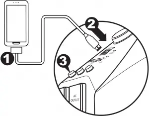
The Powerpack’s dual AC outlets ports can power two AC appliances at once, up to a total of 240 W for Powerpack Pro 1100, or 480W for Powerpack Pro 1300. For best results, ensure that your Powerpack is fully charged before using the AC outlets.
- Press the AC outlet ON/OFF Switch to the ON position.
- Open the protective cover on the AC power outlet and plug the AC appliance in.
- Fully recharge the Powerpack as soon as possible after each use.
- In the event of an overload, low battery voltage or overheating, the Powerpack automatically shuts down.

Understanding appliance wattage
- AC appliances are rated by how much electrical power (in watts) they consume. The fewer watts an AC appliance uses, the longer the powerpack will operate before recharging is required.
- Some appliances may be difficult or impossible to operate from the Powerpack if they have a high surge rating or are not suitable for use with the Powerpack.
Trouble Appliances
To avoid damage to your AC appliance, the Powerpack is not recommended for use with the following:
- Electronics that modulate RF (radio frequency) signals on the AC line.
- Speed controllers found in some fans, power tools, kitchen appliances, and similar appliances.
- Some chargers for small rechargeable batteries can be damaged.
- Metal halide arc (MHI) lights can be damaged.
High Surge Appliances
“Surge” power is the initial amount of power required to start an appliance.
- Appliances such as televisions and appliances with motors consume much more power than their average (continuous use) rating when they are first switched on. This may exceed the capabilities of the Powerpack and trigger the safety overload shutdown circuit.
6. Using the 12V DC power outlet
The Powerpack can operate 12 V DC appliances (such as those that plug into a vehicle’s lighter socket) that draw 20 Amps of power or less.
- Open the protective cover on the DC power outlet and plug your appliance into the port.
- Turn the appliance on (if required). The Powerpack will automatically supply power to your appliance.
- Fully recharge the Powerpack as soon as possible after use.
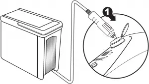
Battery power drain
- As the DC power outlet is internally wired directly to the Powerpack’s battery, it does not automatically switch off. Check the battery status periodically to prevent total battery discharge.
- Extended operation of a 12 V DC appliance may result in excessive battery discharge.
High-consumption DC appliances
- If your 12V DC appliance draws more than 20 Amps, the Powerpack’s internal circuit breaker shuts off the power to your appliance. You will not be able to use this appliance with the Powerpack. If shutoff occurs, unplug your appliance. The Powerpack’s internal circuit breaker automatically resets after a few seconds.
7. Jump-starting your vehicle
Please read these critical safety instructions carefully before jump-starting a car with the Powerpack.
Fire Safety
- Never allow jump-start cables’ red and black clamps to touch each other or another common metal conductor. This could damage the Powerpack and/or create a sparking/explosion hazard. Always switch OFF the Jump-Start power switch and store the jump-start clamps in the appropriate holder on each side of the Powerpack after use.
- Do not crank your vehicle’s engine for more than 4 seconds. The jump-start feature is designed for short term operation only. Operating the jump-start feature for more than 4 seconds may damage the Powerpack.
- Always allow the Powerpack to cool down for at least 3 minutes after each jump-start.
Personal Safety
- Always turn OFF the vehicle or boat ignition and all accessories.
- Engage the park or emergency brake and place the transmission in park for an automatic or neutral for a manual.
- If jump-starting a boat engine, purge the engine compartment and bilge of all fumes.
- Position the Duracell® Powerpack Pro on a flat, stable surface near the battery and away from all moving parts of the engine. Ensure that the jump-starting power switch is OFF.
Jump-starting your vehicle
- Remove the clamps from the holsters on each side of the Powerpack.
- Connect the red positive (+) clamp of the cables to the positive (+) terminal of the engine battery. The battery’s positive terminal is usually larger in diameter than the negative terminal. In most vehicles, the battery’s positive terminal has a red wire connected to it.
- Connect the black negative (-) clamp of the cables to the engine block, cylinder head, or other stationary heavy metal part of the motor.
Red POSITIVE (“+”) Clamp connects to positive battery terminal
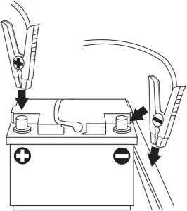
Black NEGATIVE (“-“) clamp connects to negative battery terminal or metal part of car (block, cylinder, etc)
4. If the “Clamps Reversed” LED illuminates, then reverse polarity has been detected. Disconnect the jump-start clamps from the vehicle’s battery and redo steps 1 and 2.
5. Switch ON the jump-starting power switch. Before starting the engine, make sure the Duracell® Powerpack Pro and the cables are clear of belts and fans.
6. Crank the engine for 4 seconds or until it starts, whichever is first.
8. Using the air compressor
Please read these critical safety instructions carefully before using the Powerpack’s air compressor.
Fire Safety
- The compressor is designed for short term operation only. Operating the compressor over an extended period of time will cause the compressor unit to overheat which could lead to fire.
- The powerpack cannot be used to inflate large capacity inflatables such as float tubes, large air mattresses, and inflatable boats. These types of products require extended inflating times that may damage the compressor.
- Always allow the compressor to cool down for 10 minutes after each 10 minutes of continuous operation.
Personal Safety
- Never leave the compressor unattended while in operation. Keep out of reach of children.
- The compressor is capable of inflating to 150 PSI. Do not exceed the recommended pressure of either the compressor or the object being inflated. If either recommended pressure is exceeded, an explosion may result.
- If the pressure gauge on the compressor indicates more than twice
the recommended pressure for the object you are inflating, and you have only started to inflate the object, the valve connector is incorrectly connected to the valve stem. This may damage the Powerpack. Remove and reattach the valve connector to the valve stem.
Inflating tires (car, motorcycle, bicycle)
1. Remove the air compressor hose from the rear of the Powerpack.

2. Place the valve connector securely on the tire valve stem, push it as far as possible to allow normal airflow, and close the thumb latch. If necessary, use a supplied nozzle adapter.
3. Press the Air Compressor switch to turn the compressor on, and inflate your tire to its recommended pressure.
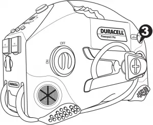
4. Switch the compressor off after appropriate pressure is reached.
5. Open the thumb latch and remove the valve connector from the valve stem.
6. Check the air pressure of the tire with a pressure gauge.
Inflating tires (car, motorcycle, bicycle)
- Place the valve connector fully on or into the valve receptacle on the item.
- Turn the compressor on and inflate to appropriate pressure.
You may also use a supplied nozzle adapter:
1. Locate proper nozzle adapter stored in the compartment near the Power pack’s handle.
2. Insert nozzle adapter into the valve receptacle of the item.
3. Turn the compressor off before removing nozzle adapter from valve stem.
4. Remove nozzle adapter from valve connector and return it to the storage compartment.
9. Connecting to an external battery
You can extend battery operating times by connecting the Powerpack to a larger external battery. For example, an external 54Ah battery gives approximately three times the operating time of the Powerpack’s own internal 18Ah or 15Ah battery.
Please read these critical safety instructions carefully before connecting the Powerpack to an external battery for the first time.
Fire Safety
- Never allow jump-start cables’ red and black clamps to touch each other or another common metal conductor. This could damage the Powerpack and/or create a sparking/explosion hazard.
- Jump-start cable clamps must be connected positive to positive (red clamp to battery “+”) and negative to negative (black clamp to battery A reverse polarity connection (positive to negative) may damage the Powerpack and/or create a sparking/explosion hazard.
Personal Safety
- Use a sealed, non-spillable external battery for indoor use. Common auto and marine batteries are not suitable for indoor use unless their fumes are vented outdoors. Common auto and marine batteries contain acid, which is hazardous if spilled.
- Wear eye protection and protective clothing when connecting the powerpack to an external battery.
To connect the Powerpack Pro to an external battery using the jump-start cables:
- Ensure that the jump-start power switch is OFF.
- Connect the red positive (+) clamp of the cables to the positive (+) terminal of the external battery.
- Connect the black negative (-) clamp of the cables to the negative (-) terminal of the external battery
- If the “Clamps Reversed” LED illuminates, then reverse polarity has been detected. Disconnect the jump-start clamps from the vehicle’s battery and redo steps 1 and 2.
- Disconnect the jump-start clamps from the battery and redo steps 2 and 3 in this procedure.
- Switch ON the jump-start power switch.
To disconnect: - Ensure that the jump-start power switch is OFF.
- Remove the red positive (+) clamp, and then remove the black negative (-) clamp from the external battery terminals.
- Store the jump-start clamps in the appropriate holder on each side of the Powerpack.
- Recharge the powerpack as soon as possible after use.
10. Powerpack maintenance
Battery charging
All rechargeable batteries gradually discharge when left standing, and you need to recharge them periodically to maintain maximum battery capacity. The charger within the Powerpack is designed to regulate the charging process, ensuring that the battery is always fully charged but never overcharged. To ensure safe recharging and maximum battery life, recharge the Powerpack only with the supplied charger.
Please be sure to fully recharge your Powerpack every three months. This is important to maintain maximum life and usability of your Powerpack’s battery.
Leaving a battery in a discharged state may result in permanent battery damage and poor jump-starting performance.
Personal Safety
- Disconnect all sources of AC power and DC power before performing any type of maintenance to prevent accidental shock.
- Do not attempt to recharge the Duracell® Powerpack Pro battery if it is frozen. Gradually warm the frozen battery to 32 °F (0 °C) before recharging.
- Please see Section 1: “Charging/Recharging your Powerpack” for full instructions.
- Please also refer to Section 2: “Checking the battery level” for additional information.
- In addition to recharging the Powerpack’s battery, it is recommended to periodically clean the outside of the Powerpack with a damp cloth to remove the accumulated dust and dirt.
11. Recycling
If it’s rechargeable, it’s recyclable! Battery-Biz is committed to environmental responsibility and has established a program for recycling Duracel® rechargeable battery-related products.
For instructions on how to recycle this product visit http://www.call2recycle.org.
12. Troubleshooting
Below are some common problems that can occur with the Powerpack. If you cannot solve your problem, contact your dealer or Duracell Customer Service at (800) 842-2127.
Problem: AC appliance will not operate.
Possible Cause : Solution
AC appliance rated more than 300 W (Powerpack Pro 1100) or 600 W (Powerpack Pro 1300): the safety overload has tripped. : Use an AC appliance with a lower power rating.
AC appliance is rated less than 300 W (Powerpack Pro 1100) or 600 W (Powerpack Pro 1300): high starting surge has tripped the safety overload. : AC appliance may exceed the Duracell® Powerpack Pro’s surge capability. Use an AC appliance with a starting surge within the Duracell® Powerpack surge rating.
Battery has discharged to 10.5 V. : Turn OFF the AC Power ON/OFF switch and recharge the Duracell® Powerpack.
Duracell® Powerpack Pro has overheated due to poor ventilation or excessively warm environmental conditions. : Turn the AC Power ON/OFF switch OFF and allow the Duracell® Powerpack Pro to cool for 15 minutes or more. Clear blocked openings or remove objects covering the unit, then restart the Duracell® Powerpack and move it to a cooler environment.
Problem: Overload shutdown.
Possible Cause : Solution
Appliance power requirements exceed the capability of the Duracell® Powerpack Pro. : Unplug the appliance and confirm that the appliance’s power requirement is 300 W (Powerpack Pro 1100) / 600 W (Powerpack Pro 1300) or less before attempting to restart the appliance.
Problem: Measured AC output voltage is too low.
Possible Cause : Solution
Using an average-reading AC voltmeter to read output voltage. : The modified sine wave output of the Duracell® Powerpack requires a true RMS reading meter, such as the Fluke 87 series, for accurate measurement.
Duracell® Powerpack Pro battery is almost fully discharged. : Press Battery Level button to verify battery status and recharge the Duracell® Powerpack Pro as necessary. Battery Level LEDs are only accurate when the unit has been disconnected from all appliances and all charging sources for 15 minutes.
Problem: Battery Status LED is red and has not changed to green after 24 hours of charging.
Possible Cause : Solution
The voltage at the AC wall outlet is less than 120VAC.
Use AC wall outlet that supplies 120VAC. : Continue to charge the unit for another 12 hours; the unit will be ready to use even if the Battery Status light remains red.
Problem: The engine being jump-started will not start.
Possible Cause : Solution
Duracell® Powerpack Pro battery is not fully charged. : Recharge the Duracell® Powerpack Pro battery.
The engine condition is poor. : Have the engine serviced.
The engine start capacity exceeds the Duracell® Powerpack Pro jump-start capability. : Use a higher power Duracell® . Powerpack Pro.
Problem: The jump-start clamps measure zero volts.
Possible Cause : Solution
Jump-start power switch is OFF. : Turn the jump-start power switch ON.
Duracell® Powerpack Pro battery needs to be recharged. : Recharge the battery.
Problem: The compressor runs, but won’t inflate.
Possible Cause : Solution
The valve connector may not be securely placed on the valve stem. : Make sure the valve connector is securely placed on the valve stem before closing the thumb latch.
The item being inflated may have a leak. : Make sure the item being inflated doesn’t have a leak. Check the compressor hose for any breaks or leaks.
Problem: The compressor runs slowly.
Possible Cause : Solution
The compressor may have overheated from excessive use. : Turn off the compressor and let it cool down.
Battery voltage is too low. : Check the condition of the internal battery. The battery may need to be recharged or replaced.
13. User reference: Tire inflation
The information in the table below is for reference only. For precise pressure specifications, refer to the information supplied with the item to be inflated.
Type of tire : Typical pressure specifications (PSI)
Automotive tires
520-13 26
A-78-14 26
E78-14 30
H-78-14 24
HR-78-15 28
Bicycle tires
27 x 1 ¼ 85
20 x 1 ½ 40
Other Inflatables
Football 13
Basketball 9
Volleyball 5
Lawn tractor tire 22
14. Specifications
All specifications are subject to change without notice.
12V DC section
Internal battery type : Sealed/non-spillable, AGM (Absorbed Glass Mat) lead-acid
Internal battery voltage (nominal) : 12V DC
Internal battery capacity (minimum) : DR300PWR…………………… 12Ah
DR600PWR…………………… 18Ah
DC power socket (maximum continuous load) : 20 A with automatic reset.
AC power section
Output power
- Continuous output power
DR300PWR……………240W
DR600PWR…………… 480W - Output power (5 minutes)
DR300PWR……………. 300W
DR600PWR……………. 600W - Peak AC output surge capacity
DR300PWR……………. 480W
DR600PWR……………. 750W
Output voltage 115V AC (RMS)
Output frequency 60Hz
Output wave form Modified sine wave
No load current draw <0.5 A DC
Input voltage range 10V to 15V DC
Low battery alarm 10.5V DC
Low battery shutdown 10.0V DC
High battery voltage shutdown 16V DC
Over temperature shutdown <194° F (90° C)
Overload shutdown Yes, automatic reset
AC output short circuit protection Yes, automatic reset
Fuse (Internal)
DR300PWR…40Ax 1 (MAX),
DR600PWR…35Ax 2 (MAX)
Operating temperature range 32°-104 °F (0°-40 °C)
Storage temperature range 68°-122° F (-20° C –50°C)
Internal battery charging controller system
AC input voltage range 100-240V AC
AC input frequency 50/60Hz
Output voltage 15V DC
Rated voltage in floating charge 13.2Vdc@30mA
Empty load power < 0.5W
Safety standards ETL (for the charger)
Efficiency standards BC
Air compressor
Pressure 160 PSI (lb/in)
Physical specifications
Length 15.2 in. / 38.5 cm
Width 9.3 in. / 23.7 cm
Height 10.7 in. / 27.2 cm
Weight DR300PWR 16.8 lbs. / 7.6 kg, DR600PWR 20.9 lbs. / 9.5 kg
Accessories
AC cord 52.4 in. (133cm)
Compressor nozzles Red air nozzle, blue air nozzle, inflator needle
15. Contacting Customer Support
If you experience any problems or have any questions regarding your DURACELL® product, free technical support is available. Prior to calling, please review the technical support tips below. Call from a phone where you have access to your mobile device.
Be prepared to provide the following information:
– Name, address and telephone number
– Name of the DURACELL® product
– Make and model of your device
– Symptoms of the problem(s) and what led to them
Technical Support is available by telephone:
U.S. and Canada (800) 300-1857
Outside of the US/Canada: (805) 437-7765
Written inquires should be directed to:
Battery-Biz Inc.
DURACELL® Product Inquiry
1380 Flynn Road, Camarillo, CA93012, USA
16. Warranty and Return Information
Two Year Limited Warranty
The DURACELL® product carries a limited warranty against defects in material and workmanship under normal use and service for two years from the original date of purchase. The manufacturer or distributor, at its option, shall repair or replace the defective unit covered by this warranty. Please retain the dated sales receipt as evidence of the date of purchase as it will be required for any warranty service. In order to keep the warranty in effect, the product must have been handled and used as described in the instructions accompanying this warranty. This warranty does not cover any damage due to accident, misuse, abuse or negligence.
Disclaimer Of Warranty
The limited warranty described herein is your sole remedy. To the extent permitted by law, the manufacturer and distributor disclaim all other implied or express warranties including all warranties of merchantability and/or fitness for any particular purpose.
Limitation Of Liability
Except to the extent of repairing or replacing this product as expressly stated in the limited warranty described herein, the manufacturer and distributor shall not be liable for any damages, whether direct, indirect, incidental, special, consequential, exemplary, or otherwise, including lost revenues, lost profits, loss of use of software, loss or recovery of data, rental of replacement equipment, downtime, damage to property, and third-party of replacement equipment, downtime, damage to property, and third-party claims, arising out of any theory of recovery, including statutory, contract or tort. Not withstanding the term of any limited or implied warranty, or in the event that any limited warranty fails of its essential purpose, in no event will the manufacturer’s and distributors entire liability exceed the purchase price of this product. Some states and provinces do not allow the exclusion or limitation of incidental or consequential damages so the above limitations or exclusions may not apply to you. This limited warranty gives you specific legal rights. You may have other rights which vary from state to state and province to province.
Pursuant to California Proposition 65, this product contains chemical(s) known to the State of California to cause cancer, birth defects, or other reproductive harm.
© 2016 Duracell. DURACELL’ is a registered trademark of Duracell, U.S. Operations, Inc., used under license. All rights reserved. All logos and trademarks are used for identification purposes only and may be trademarks or registered trademarks of their respective holders.
UM-DRPP300-600 Rev 20170111
]]>DURACELL 6 Amp Battery Charger / Maintainer
1. Features
6 Amp Battery Charger
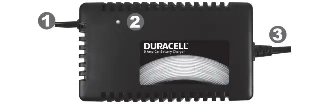
1: DC Output Cable connects to the charging cables (shown below), providing power to the battery being charged
2: LED Charging Indicator shows the status of the charging process (see “LED Charging Indicator” section)
3: AC Power Input Cord connects the battery charger to a standard AC wall outlet
Quick-Connect Charging Cables (included)
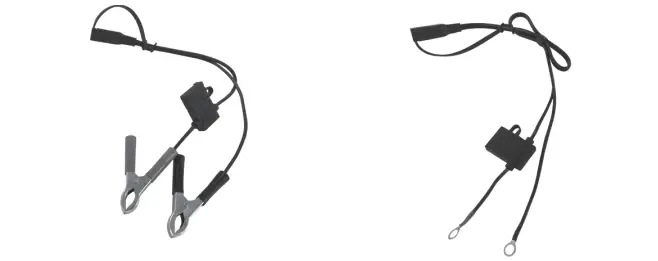
Battery charging clamps connect to battery terminals for fast direct charging
Ring terminals permanently attach to battery for easy frequent recharging
2. Important Safety Information
- Warnings identify conditions that may result in personal injury or loss of life.
- Cautions identify conditions or practices that may damage the unit or other equipment

FCC INFORMATION TO THE USER
This equipment has been tested and found to comply with the limits for a Class B digital device, pursuant to part 15 of the FCC Rules. These limits are designed to provide reasonable protection against harmful interference in a residential installation. This equipment generates, uses and can radiate radio frequency energy and, if not installed and used in accordance with the instruction guide, may cause harmful interference to radio communications. Operation of this equipment in a residential area is likely to cause harmful interference in which case the user will be required to correct the interference at his own expense.
IMPORTANT
This guide contains important safety and operating instructions in how to use the battery charger to recharge 12V vehicle batteries.
- Do not expose the battery charger to moisture, rain, or snow.
- Use of an attachment not recommended by the battery charger manufacturer may result in a risk of fire, electric shock, or injury to persons.
- To reduce risk of damage to electric plug and cord, pull by plug rather than cord when disconnecting the battery charger.
- Do not operate the battery charger with damaged cord or plug — have the cord or plug replaced.
- Do not operate the battery charger if it has received a sharp blow, been dropped, or otherwise damaged in any way; contact the manufacturer for repair or replacement.
- Do not disassemble the battery charger. Incorrect reassembly may result in shock or fire hazard.
- To reduce risk of electric shock, unplug the battery charger from the electric outlet before attempting any maintenance or cleaning.
WARNING: RISK OF EXPLOSIVE GASES
Working in the vicinity of a lead-acid battery is dangerous. Batteries generate explosive gases during normal battery operation. For this reason, it is of utmost importance that each time before using a battery charger, you read this guide and follow the instructions exactly. To reduce risk of battery explosion, follow these instructions and those published by battery manufacturer and manufacturer of any equipment you intend to use in the vicinity of the battery. Review cautionary marking on these products and on any engine.
Personal Precautions
- Someone should be within range of your voice or close enough to come to your aid when you work near a lead-acid battery.
- Have plenty of fresh water and soap nearby in case battery acid contacts skin, clothing, or eyes.
- Wear complete eye protection and clothing protection. Avoid touching eyes while working near battery.
- If battery acid contacts skin or clothing, wash immediately with soap and water. If acid enters eye, immediately flood eye with running cold water for at least 10 minutes and get medical attention immediately.
- NEVER smoke or allow a spark or flame in the vicinity of battery or engine.
- Be extra cautious to reduce risk of dropping a metal tool onto a battery. It might spark or short-circuit the battery or other electrical part that may cause an explosion.
- Remove personal metal items such as rings, bracelets, necklaces, and watches when working with a lead-acid battery. A lead-acid battery can produce a short-circuit current high enough to weld a ring or the like to metal, causing a severe burn.
- Use 6 AMP Battery Charger for charging a 12 V LEAD-ACID battery only. It is not intended to supply power to a low voltage electrical system. Do not use 6 AMP Battery Charger for charging dry-cell batteries that are commonly used with home appliances. These batteries may burst and cause injury to persons and damage to property.
- NEVER charge a frozen battery.
Charger Location
- Place the battery charger as far away from the battery as the output DC cable permits.
- Never place the battery charger directly above a battery being charged; gases from battery will corrode and damage the charger.
- Never allow battery acid to drip on the charger when reading specific gravity or filling battery.
- Do not operate the charger in an enclosed area. Do not restrict ventilation in any way.
- Do not set a battery on top of the charger.
DC Connection Precautions
- Connect and disconnect the DC cable only after removing the AC cord from the electric outlet.
- When attaching the clips to the battery posts, twist or rock back and forth several times to make a connection. This tends to keep the clips from slipping off the terminals and helps to reduce the risk of sparking.
Failure to follow these safety guidelines may cause personal injury and/or damage to the 6 AMP Battery Charger. It may also void your product warranty.
3. Preparing To Charge
- If necessary to remove the battery from the vehicle to charge, always remove the grounded terminal from the battery first. Make sure all accessories in the vehicle are off, so to minimize chances of an arc.
- Be sure the area around the battery is well-ventilated while the battery is being charged. Gas can be forcefully blown away by using a piece of cardboard, other nonmetallic material or a fan.
- Clean battery terminals. Be careful to keep corrosion from coming in contact with eyes.
- Study all battery manufacturer’s specific precautions such as removing or not removing cell caps while charging and recommended rates of charge.
- Add distilled water in each cell until battery acid reaches level specified by the battery manufacturer. This helps purge excessive gas from cells. Do not overfill. For a battery without cell caps, carefully follow manufacturer’s recharging instructions.
- Determine the voltage of battery by referring to the vehicle owner’s manual and make sure it matches the output rating of the battery charger. If the charger has a variable rate of charge, begin charge at lowest rate initially.
4. Three Stage Battery Charging Process
Multi-stage charging ensures batteries receive optimum charging, but with minimal wear and tear, regulating the voltage and current delivered to the batteries in three automatic stages.
- Bulk: Replaces 70-80% of the battery’s state of charge at the fastest possible rate.
- Absorption: Replenishes the remaining 20-30% of charge, bringing the battery to a full charge at a slow, safe rate.
- Float: Voltage is reduced and held constant in order to prevent damage and keep batteries at a full charge.
5. LED Charging Indicator
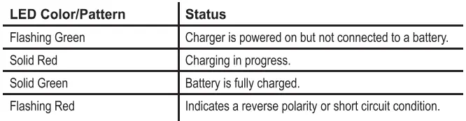
6. Using Your Charger
It is possible to use the 6 AMP Battery Charger to charge most engine starting batteries when the battery is installed in a vehicle. Before attempting to charge a vehicle battery, make sure the battery is a 12 volt, lead-acid type.
NOTE
The battery charger will not produce an output voltage until it senses at least 8 Volts from the battery. It must be connected to a battery with the correct polarity before it will start charging a battery. Therefore, if you plug the AC power cord into an AC power outlet, and if the output alligator clips or ring terminals are not connected to a battery, and if you touch the alligator clips or ring terminals together, there will be no electrical spark.
WARNING: EXPLOSION HAZARD
A spark near the battery may cause an explosion. Follow instructions carefully to reduce the risk of spark near the battery. Do not face the battery when making the final connection.
Preparing To Charge
- Turn off any lights, audio equipment, or other 12 volt accessories that are connected to your vehicle’s electrical system. Make sure your vehicle is in the park position and secured by the emergency brake.
- Position the AC and DC cords to reduce the risk of damage by a hood, door, or moving engine part.
- Stay clear of fan blades, belts, pulleys, and other parts that can cause injury to persons.
- Check the polarity of the battery posts. The POSITIVE (POS, P, +) battery post usually has a larger diameter than the NEGATIVE (NEG, N, -) post.
- Determine which battery post is grounded (connected) to the chassis.
Charging Cable Quick-Connect Feature
This charger includes two types of charging cables:
- Battery Clamps connect directly to your vehicle battery for manual charging. This is often used for typical single-use charging in an everyday situation.
- Ring Terminals can be installed onto your vehicle battery for convenient repeated charging, and for maintaining your battery charge in a vehicle (such as a watercraft, ATV or snowmobile) which may be stored for long periods of time between uses.
To conveniently switch between these charging types, the charger features a Quick-Connect mechanism which allows you to quickly select and install the proper charging cable.
To connect the charging cable:
- Select the battery clamp or ring terminal cable and locate the quick-
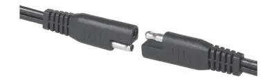
connect terminal (as shown above). - Find the corresponding quick-connect terminal on the battery charger’s attached output cord.
- Line up the silver connection post on each quick-connect terminal with its corresponding opening on the other cable’s terminal.
- Push gently but firmly to interlock the two cables. When you can no longer push and no longer see a gap between the two quick-connect terminals, the cables have been properly connected.
![]() Using The Battery Clamps (Typical Single-Use Charging)
Using The Battery Clamps (Typical Single-Use Charging)
This method is typically used for normal one-time replenishment of a discharged battery.
- Once you have connected your battery clamps to the charging cable using the steps above (see Charging Cable Quick-Connect Feature), determine which terminals are positive and negative, and which one is grounded to your vehicle chassis (see “Preparing To Charge”). If the negative battery post is grounded to chassis (as in most vehicles), see (2) below. If the positive post is grounded to the chassis, see (3) below.
- For a negative-grounded vehicle, connect the POSITIVE (RED) clip from the battery charger to the POSITIVE (POS, P, +) ungrounded post of battery. Connect the NEGATIVE (BLACK) clip to a heavy-gauge metal part of the frame or to the engine block away from the battery. Do not connect the clip to the carburetor, fuel lines, or sheet-metal body parts.
- For a positive-grounded vehicle, connect the NEGATIVE (BLACK) clip from the battery charger to the NEGATIVE (NEG, N, -) ungrounded post of battery. Connect the POSITIVE (RED) clip to a heavy-gauge metal part of the frame or to the engine block. Do not connect clip to carburetor, fuel lines, or sheet-metal body parts.
- Plug the 6 AMP Battery ChargerAC cord into a standard AC wall outlet.
- When fully charged, the LED charging indicator light turns solid green.
- Once the vehicle’s battery is fully charged, disconnect the AC cord, remove the clip from the vehicle’s chassis and then remove the clip from the battery terminal.
- Disconnect the battery clamps from the battery charger by pulling gently on each quick-connect terminal to disengage.
CAUTION: EQUIPMENT DAMAGE
To avoid damaging your charging and battery charger cables, grasp each quick-connect terminal directly. Do not pull directly on either cord.
CAUTION: EQUIPMENT DAMAGE
Do not start the vehicle’s engine while the charger is still connected to the battery. This will damage the charger and void the warranty.
![]()
Using The Ring Terminals (Extended Installation and Battery Maintenance)
Ring terminals can be left attached to the battery of any vehicle that may require frequent recharging, or if you wish to maintain a float charge that keeps the battery fully charged and ready for use. This is especially useful for motorcycles, ATVs, watercraft and other vehicles that are often stored for extended periods of time.
- Determine which terminals on your battery are positive and negative. Typically, the positive terminal has a red protective cap and/or is marked with the plus “+” sign, and the negative terminal has a black protective cap and/or is marked with the minus sign..
- Unscrew the POSITIVE (RED) cap from the positive battery terminal to expose the battery post.
- Place the POSITIVE (RED) ring terminal over the battery post and replace the cap.
- Repeat the same process for the NEGATIVE (BLACK) terminal, attaching the NEGATIVE (BLACK) ring to the battery post.
- You may now connect the ring terminals to the battery charger. Using the steps outlined in the Charging Cable Quick-Connect Feature section on Page 1, connect the ring terminals to the charger cable.
- Plug the 6 AMP Battery Charger AC cord into a standard AC wall outlet.
- When fully charged, the LED charging indicator light turns solid green.
- Once the vehicle’s battery is fully charged, disconnect the AC cord.
- Disconnect the battery clamps from the battery charger by pulling gently on each quick-connect terminal to disengage.
- You may leave the ring terminals attached to your battery for quick reconnection next time that you wish to recharge your vehicle. Simply tuck the remainder of the ring terminal cord into the battery compartment of your vehicle next to your battery, or into a similar safe place on your vehicle, to avoid damage to the cord.
CAUTION: EQUIPMENT DAMAGE
To avoid damaging your charging and battery charger cables, grasp each quick-connect terminal directly. Do not pull directly on either cord.
CAUTION: EQUIPMENT DAMAGE
Do not start the vehicle’s engine while the charger is still connected to the battery. This will damage the charger and void the warranty.
7. Specifications
DC Output Specifications

Protection Features
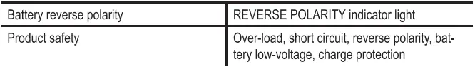
Approvals
8. Recycling Information
Battery-Biz is committed to environmental responsibility and recommends that electronic devices be disposed of properly. Please contact your local city offices for information on recycling and disposal programs for e-waste.
For instructions on how to recycle this product visit http://www.call2recycle.org.
9. Quality Guarantee
Battery-Biz guarantees each Duracell® product to be free of defects due to faulty materials or workmanship. This Duracell® charger carries a 3-year limited warranty from the date of purchase.
If found to be defective, the charger will be replaced without charge when returned to Battery-Biz. This guarantee does not apply to damage from misuse or abuse beyond normal usage. This guarantee gives you specific legal rights, and you may also have other rights which vary from state to state. Should any device be damaged by the charger due to defects in the product arising from faulty materials or workmanship, Battery-Biz will repair or replace (at our option) the device, provided both device and product usage instructions have been followed.
Send your device, along with the DURACELL® charger, to: Battery-Biz Inc.; 1380 Flynn Road, Camarillo, CA 93012; Attention: Duracell® Product Returns
If you would like additional information on Duracell® products call 1-800-300- 1857 or 1-805-437-7765 (7:30 AM-4:30 PM PST)
10. Contacting Customer Support
If you experience any problems or have any questions regarding your DURACELL® charger, free technical support is available. Prior to calling, please review the technical support tips below. Call from a phone where you have access to your mobile device
Be prepared to provide the following information:
- Name, address and telephone number
- Name of the DURACELL® product
- Make and model of your device
- Symptoms of the problem(s ) and what led to them
Technical Support is available by telephone:
U.S. and Canada 1-800-300-1857
Outside of the US/Canada: 805-437-7765
Written inquires should be directed to: Battery-Biz Inc.;
DURACELL® Product Inquiry
1380 Flynn Road, Camarillo, CA93012, USA
WARNING
This product contains chemical(s) known to the State of California to cause cancer, birth defects, or other reproductive harm.
]]>DURACELL CEF14BR4 Rechargeable Battery Charger

CORRECT DISPOSAL OF THIS PRODUCT
Please follow any local requirements to recycle used electronic appliances and rechargeable batteries.
FCC COMPLIANCE STATEMENT
This device complies with Part 15 of the FCC Rules and Class B Digital Device limits which provide protection against interference in a residential installation. Operation is subject to the following two conditions:
(1) This device may not cause harmful interference, and
(2) this device must accept any interference received, including interference that may cause undesired operation.
The device uses and radiates radiofrequency energy, and if not installed and used in accordance with the instructions or is modified, may cause interference to radio/TV communications in which the manufacturer is not responsible. Should interference occur, correct by connecting device to an outlet on a different circuit.
BATTERY CAUTION: Keep batteries away from children. If swallowed, consult a physician at once.
We recommend charging DURACELL NiMH rechargeable batteries only. Do not attempt to charge non-rechargeable batteries. Misuse could cause batteries to rupture, causing personal injury or damage. Indoor use only. Dry location use only. Risk of electric shock. Never disassemble or alter any part of the charger or batteries. Charger or batteries may become hot during charging and will cool down when charging is complete. Not recommended for use by children under 8 years old.
IMPORTANT BATTERY CHARGER SAFETY INSTRUCTIONS:
DANGER-TO REDUCE THE RISK OF FIRE OR ELECTRIC SHOCK, CAREFULLY FOLLOW THESE INSTRUCTIONS
- SAVE THESE INSTRUCTIONS: This sheet contains important safety and operating instructions for this charger.
- Before using battery charger read all instructions and caution marking on the charger, battery, and device using battery.
- CAUTION: To reduce the risk of injury, charge only NiMH rechargeable batteries. Do not charge any disposable batteries such as Alkaline, Zinc Carbon, Lithium, NiOOH, or any batteries other than NiMH, as they may burst causing personal injury and damage. Keep batteries away from fire or explosion may occur.
For proper insertion, please observe polarity indicators (+/-). - For indoor use only. Do not expose to rain or snow.
- Do not place in or near water or extreme heat.
- Do not operate charger with damaged plug.
- Do not operate charger if it has been severely damaged in any way.
- Do not disassemble charger. Disassembly may result in a risk of electric shock or fire.
- To reduce the risk of electric shock, unplug the charger from the outlet when not in use.
- This appliance can be used by children aged from 8 years and above and persons with reduced physical, sensory or mental capabilities or lack of experience and knowledge if they have been given supervision or instruction concerning use of the appliance in a safe way and understand the hazards involved. Children shall not play with the appliance. Cleaning and user maintenance shall not be made by children without supervision.
- For connection to a supply not in the U.S.A., use an attachment plug adapter of the proper configuration for the power outlet.
- This power unit is intended to be correctly oriented in a vertical or floor mount position.
CHARGING INSTRUCTIONS
- Load NiMH batteries into the Charger.
Insert batteries into charging slots with the (+) and (-) ends oriented correctly. To charge either 2 or 4 AA/AAA use the following positions:
- Plug the charger into an AC outlet.
- CHARGING/LED INDICATION
- LED lights will cycle through RED and then GREEN when batteries are first inserted correctly
and charger is plugged in. - LED lights will turn RED when batteries are charging.
- LED lights will BLINK GREEN when the batteries are ready to use.
- LED lights will turn GREEN when the batteries become charged.
- LED lights will blink RED* if abnormal conditions are detected during charging, charging will stop.
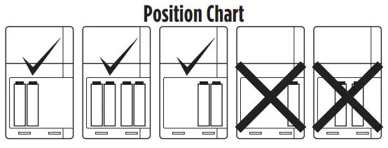
- * If Blinking Red LED is encountered, first ensure you are attempting to charge
a NiMH AA or AAA battery only. If yes, remove and reinsert the NiMH battery. If battery has become heated, it may be damaged. Insert a new NiMH battery.
- LED lights will cycle through RED and then GREEN when batteries are first inserted correctly
- STORAGE
• Unplug the charger and remove the batteries, once charging is complete.
NOTES & USAGE TIPS
- Batteries will automatically stop charging when full charge is reached.
- Safety protections will prevent battery from overcharging.
- Batteries that are new or have been stored for an extended period may need to be charged and used 2-3 times before optimal charge performance is achieved.
- New non-pre-charged batteries may require charging before use.
- This charger is capable of accepting 100-240 V AC, 50/60 Hz and, therefore, can be used overseas with a corresponding regional plug converter.
- Charging time may vary based on battery capacity (mAh).
FABRICADO EN/EM PAPEL RECICLADO MANUFACTURED ON RECYCLED PAPER
© 2017 DURACELL Hecho en China / Fabricado na China / Made in China www.duracell.com.br
]]>1100 Amp Li-Ion Jump-Starter
(DRLJS110B/DRBTLC) ![]()

Misusing or incorrectly connecting the DURACELL® Jump-Starter may damage the equipment or create hazardous conditions for users.
1. Download the PowerHub™ app
The PowerHub™ app enables advanced features:
- Battery monitoring and alerts
- Interactive step-by-step guide
- Live support
► Download the  app to get started:
DuracellPower.com/App


Scan for app download
2. Product details


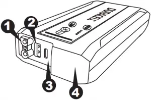

1: Jump-start port connects to jump-start clamps.
2: USB port (2.4 Amps) charges smartphones, tablets and other devices.
3: Charging ‘IN’ port connects to USB cable to recharge the Jump-starter.
4: LED flashlight features high beam, low beam and emergency/SOS mode.
5: Battery level button and LED gauge displays battery charge level.
6: LED status light bar indicates state of the Jump-Starter connection (see Section 7).
7: Light button activates the LED flashlight.
8: Bluetooth button Hold 3 seconds for pairing mode (requires Duracell Power App).
9: Jump-start clamps with SafeJump™ feature.
10: Carry bag fits into most vehicle glove boxes.
11: DC charger and USB cable for recharging the Jump-Starter.
3. Charging the Jump-starter
Disconnect jump-start clamps before charging the Jump-starter.
Do not attempt to recharge the Jump-starter battery if it is frozen.
Gradually warm the frozen battery to 32 °F (0 °C) before recharging.
Prior to using the Jump-starter for the first time, ensure that the battery of the Jump-starter is fully charged. If the battery has been fully discharged, charging with a USB charger may take up to 4 hours.
For fastest possible recharging time, please be sure to use an AC or DC charger with a rating of 2.0 Amps or higher. The charge times shown assume the usage of a charger with a 2.0A or higher power rating.
The included DC charger is for charging only Li-Ion type rechargeable batteries. Other types of batteries may burst causing personal injury or damage.
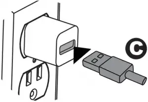
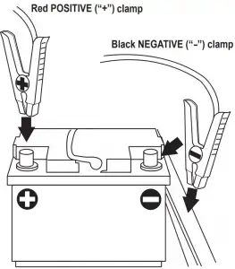

► Charging/re-charging the Jump-Starter
Charging times: Partially discharged (or after using jump-starter) – 30-60 minutes; fully discharged jump-starter battery – up to 4 hours
Charging with the included DC charger:
- Disconnect any cables from the Jump-starter and USB ports.
- Plug the DC charger into the included 12V vehicle socket (Fig. A) and connect the small micro USB end of the included USB charging cable to the ‘IN’ port. (Fig. B)
- It is best to have the vehicle running while charging.
Charging with an AC charger (sold separately):
- Disconnect any cables from the Jump-starter and USB ports.
- Plug the USB cable into your USB wall charger (Fig. C – wall charger sold separately) and connect the small micro USB end of the included USB charging cable to the ‘IN’ port (Fig. B).
If you keep the Jump-starter in storage, the battery will discharge over time. Remember to recharge the battery after every use to make sure it is ready when you need it, and at least once a year. Re-charging more often will not harm the Jump-starter.
4. Checking the Jump-starter’s battery level
To check the battery’s charge level, press the battery level button on the JumpStarter. The LED fuel gauge will illuminate and display the current level of available battery power. Four lights indicate a 100% charge.
Your Jump-starter will perform best when its battery is fully charged. If the LED Fuel Gauge shows less than 100% charge, it is recommended to fully recharge its battery (see Section 4: “Charging the Jump-starter”).
5. Using the LED flashlight and USB port
► Using the LED light
The DURACELL® Jump-Starter has a built-in emergency light to provide a safe, bright work light on the roadside and in other outdoor environments.
Press and release the light button to cycle through the 3 light modes. (High beam, Low Beam and SOS)
► Using the USB port
The USB port provides up to 2.4 Amps of current to charge cell phones, smartphones, tablets and other devices.
- Open the protective cover over the USB port.
- Connect your USB device (smartphone, tablet, etc.) to the USB port using the USB cable supplied with your device.
- Charging will automatically start.
6. Jump-starting a vehicle
You can use the DURACELL® Jump-Starter with the supplied jump-start clamps to jump-start a vehicle or boat engine. The Jump-Starter is compatible with 12V vehicles.
Do not crank the engine for more than 4 seconds. The jump-start feature is designed for short term operation only. Operating the jump-start feature for more than 4 seconds may cause damage to the unit. Allow the Jump-starter to cool down for at least 30 seconds after each jump-start.
► To jump-start a vehicle engine:
1. Connect the jump-start clamps to the Jump-Starter
2. Connect the red (+) clamp to the positive (+) terminal on the vehicle battery and the black (-) clamp to the negative (-) terminal on the vehicle battery
3. Verify that the Jump-Starter and clamps are clear of any moving engine parts.
4. Start your engine, Be sure to crank for no more than 4 seconds at a time and allow for 30 seconds in between starting attempts.
5. After starting the vehicle remove the Jump-starter and recharge it.
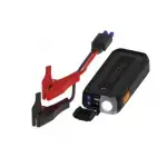
Red POSITIVE (“+”) clamp connects to positive battery terminal
Black NEGATIVE (“-”) clamp connects to the negative battery terminal OR metal part of car (block, cylinder, etc)
7. Jump-Start LED bar function
| Jump-start LED bar | Reason and suggestion |
| OFF | No clamp cable connected |
| Green flash | Clamp cable connected, ready to connect to vehicle |
| Green flash (still flashing after 5 seconds of connection to battery) | 1. Turn off all vehicle accessories and lights; wait 5-10 minutes before reconnecting and try again. 2. If still flashing, the car battery may be below 3V and is unsafe to use with this jump-starter. |
| Solid Green | Good voltage and polarity – ready to start |
| Solid Red and beeping while connecting | Reverse polarity or short – recheck connections |
| Solid Red – OR – 4 Fuel Gauge LEDs flashing – After extended starting | Over temperature – wait for the unit to cool down and reset. |
| Solid Red + 1 or 2 LED on fuel gauge | Low internal battery voltage, please fully charge the unit |
| OFF – after 10 minutes | Timed-out for safety, press power button to reset or re-attach red clamp |
| Green flash after vehicle starts | Reverse charge protection – Vehicle started, remove the unit |
8. Specifications
Electrical specifications
| Charging Input Voltage/Current | 5V/2.0A |
| DC Adapter Input Voltage | 12V |
| DC Adapter Output Voltage/Current | 5V / 2.1 A |
| Safety certifications / efficiency certifications | UL (cTUVus), CEC/BC, FCC
(DC charger: CE,FCC) |
Physical specifications
| Length | 7.66 in (19.45 cm) |
| Width | 3.31 in (8.40 cm) |
| Height | 1.40 in (3.55 cm) |
| Weight (product only) | 1.47 lbs (490 g) |
9. Important safety instructions
IMPORTANT: Please read these general usage-related warnings and cautions thoroughly before using this Jump-starter.
- Read all the instructions before using the product.
- To reduce the risk of injury, close supervision is necessary when the product is used near children.
- Do not insert fingers or foreign objects into the product.
- Do not use this product with any application of which it was not intended.
- Use of an attachment not recommended or sold by the manufacturer may result in risk of fire, electric shock or injury to persons.
This product is NOT tested, designed nor intended to be used with life support systems or any other medical devices.
- Do not use the product if it is damaged or modified. Damaged or modified batteries may exhibit unpredictable behavior resulting in fire, explosion or risk of injury.
- Do not operate the power pack with a damaged cord or plug.
- Do not disassemble the power pack, contact the manufacturer when service or repair is required. Incorrect reassembly may result in a risk of fire or electric shock.
WORKING IN THE VICINITY OF A LEAD ACID BATTERY IS DANGEROUS. BATTERIES GENERATE EXPLOSIVE GASES DURING NORMAL BATTERY OPERATION. FOR THIS REASON, IT IS OF THE UTMOST IMPORTANCE THAT YOU FOLLOW THE INSTRUCTIONS EACH TIME YOU USE THE JUMP-STARTER.
To reduce risk of vehicle battery explosion, follow these instructions in vicinity of the battery. Review cautionary marking on this product and on vehicle engine.
- Consider having someone close enough by to come to your aid when you work near a lead-acid battery.
- Have plenty of fresh water and soap nearby in case battery acid contacts skin, clothing, or eyes. Wear complete eye protection and clothing protection. Avoid touching your eyes while working near a vehicle battery.
- If battery acid contacts skin or clothing, wash immediately with soap and water. If acid enters eye, immediately flood eye with running cold water for at least 10 minutes and get medical attention immediately.
- NEVER smoke or allow a spark or flame in vicinity of a vehicle battery or engine.
- Be extra cautious to reduce risk of dropping a metal tool onto the vehicle battery. It might spark or short-circuit battery or other electrical part that may cause an explosion.
- Remove personal metal items such as rings, bracelets, necklaces, and watches when working with a lead-acid battery. A lead-acid battery can produce a short-circuit current high enough to weld a ring or the like to metal, causing a severe burn.
- When charging the internal battery, work in a well ventilated area and do not restrict ventilation in any way.
- Under abusive conditions, liquid may be ejected from the battery, avoid any contact with this material. If contact accidentally occurs, flush with water. If liquid contacts eyes, additionally seek medical help. Liquid ejected from the battery may cause irritation or burns.
- Do not expose a power pack to fire or excessive temperature. Exposure to fire or temperature above 265°F (130°C) may cause an explosion.
- Attach output clamps to a battery and chassis as indicated in these instructions. Never allow the output clamps to touch one another.
10. Recycling
DURACELL® is committed to environmental responsibility and recommends that electronic devices be disposed of properly. Please contact your local city offices for information on recycling and disposal programs for e-waste.
For instructions on how to recycle this product visit http://www.call2recycle.org.
11. Contacting Customer Support
If you experience any problems or have any questions regarding your DURACELL® product, free technical support is available. Prior to calling, please review the technical support tips below. Call from a phone where you have access to your mobile device
Be prepared to provide the following information:
– Name, address and telephone number
– Name of the DURACELL® product
– Make and model of your device
– Symptoms of the problem(s) and what led to them
Technical Support is available by telephone:
U.S. and Canada to 1-800-300-1857
Outside of the US/Canada: 1-805-437-7765
Written inquires should be directed to:
DURACELL® Product Inquiry
1380 Flynn Road, Camarillo, CA 93012, USA
Email inquires should be directed to:
[email protected]
12. Warranty and return information
Two Year Limited Warranty
The DURACELL® product carries a limited warranty against defects in material and workmanship under normal use and service for two years from the original date of purchase. The manufacturer or distributor, at its option, shall repair or replace the defective unit covered by this warranty. Please retain the dated sales receipt as evidence of the date of purchase as it will be required for any warranty service. In order to keep the warranty in effect, the product must have been handled and used as described in the instructions accompanying this warranty. This warranty does not cover any damage due to accident, misuse, abuse or negligence
Disclaimer Of Warranty
The limited warranty described herein is your sole remedy. To the extent permitted by law, the manufacturer and distributor disclaim all other implied or express warranties including all warranties of merchantability and/or fitness for any particular purpose.
Limitation Of Liability
Except to the extent of repairing or replacing this product as expressly stated in the limited warranty described herein, the manufacturer and distributor shall not be liable for any damages, whether direct, indirect, incidental, special, consequential, exemplary, or otherwise, including lost revenues, lost profits, loss of use of software, loss or recovery of data, rental of replacement equipment, downtime, damage to property, and third-party claims, arising out of any theory of recovery, including statutory, contract or tort. Not withstanding the term of any limited or implied warranty, or in the event that any limited warranty fails of its essential purpose, in no event will the manufacturer’s and distributors entire liability exceed the purchase price of this product. Some states and provinces do not allow the exclusion or limitation of incidental or consequential damages so the above limitations or exclusions may not apply to you. This limited warranty gives you specific legal rights. You may have other rights which vary from state to state and province to province.
FCC Statement
This device complies with Part 15 of the FCC Rules. Operation of this product is subject to the following two conditions: (1) this device may not cause harmful interference, and (2) this device must accept any interference received, including interference that may cause undesired operation.
This equipment has been tested and found to comply within the limits for a class B digital device, pursuant to Part 15 of the FCC Rules. These limits are designed to provide reasonable protection against harmful interference in a residential installation. This equipment generates, uses, and can radiate radio frequency energy and, if not installed and used in accordance with the instructions, may cause harmful interference to radio communications. However, there is no guarantee that interference will not occur in a particular installation. If this equipment does cause harmful interference to radio or television reception, which can be determined by turning the equipment off and on, the user is encouraged to try to correct the interference by one or more of the following measures:
- Reorient or relocate the receiving antenna.
- Increase the separation between the equipment and receiver.
- Connect the equipment into an outlet on a circuit different from that to which the receiver is connected.
- Consult the dealer or an experienced technician for help.
Changes or modifications not expressly approved by the party responsible for compliance with the FCC Rules could void the user’s authority to operate this equipment.
Canada IC Statement
This equipment complies with Industry Canada radiation exposure limits set forth for an uncontrolled environment.
This device contains license-exempt transmitter(s)/receiver(s) that comply with Innovation Science and Economic Development Canada’s license-exempt RSS(s). Operation is subject to the following two conditions:
1. This device may not cause interference.
2. This device must accept any interference that may cause undesired operation of the device.
13. Product Registration
For complete warranty coverage, please register your Duracell product within fourteen days of purchase.
Visit DuracellPower.com/Register
or scan the QR code below to register.

© 2019 Duracell. Bethel, CT 06801. DURACELL® is a registered trademark of Duracell U.S. Operations, Inc., used under license. All rights reserved. All logos and trademarks are used for identification purposes only and may be trademarks or registered trademarks of their respective holders.
The Bluetooth® word mark and logos are registered trademarks owned by Bluetooth SIG, Inc. and any use of such marks by Battery-Biz Inc. is under license. Other trademarks and trade names are those of their respective owners.
UM-DRLJS110B/DRBTLC Rev 20190807
]]>