Garmin AIS 800 Installation Guide

![]()
See the Important Safety and Product Information guide in the product box for product warnings and other important information.
![]()
To avoid possible personal injury, always wear safety goggles, ear protection, and a dust mask when drilling, cutting, or sanding.
To avoid possible personal injury or damage to the device and vessel, disconnect the vessel’s power supply before beginning to install the device.
To avoid possible personal injury or damage to this device and vessel, only install this device when the vessel is on land, or when properly secured and docked in calm water conditions.
NOTICE When drilling or cutting, always check what is on the opposite side of the surface to avoid damaging the vessel.
FCC Compliance
NOTICE
In the USA, it is prohibited under FCC regulations to enter incorrect or improper data, and it is prohibited for any person other than the manufacturer or the installing dealer to input an MMSI number.
It is a violation of the rules of the FCC to input an MMSI number that has not been properly assigned to the user, or to otherwise input any inaccurate data in this device.
Assigning Data to the Device
![]()
When programmed with a valid MMSI number, this device allows you to transmit AIS signals with vessel position data. This device is meant to enhance situational awareness and may not prevent vessel collisions in all circumstances. It is your obligation to be aware of your surroundings and to ensure safe operation of the vessel.
![]()
You must program the Garmin AIS 800 device with a valid vessel MMSI number before installing the device on your boat. By default, the device operates in silent mode until you program the device with a valid vessel MMSI number. In silent mode, the device receives, but does not transmit, AIS signals with position data. You can program the device to transmit static vessel data including the vessel name, call sign, type, and dimensions, including the location of the vessel’s GPS antenna.
You can program the device to transmit vessel position data and static vessel data including the vessel name, call sign, type, dimensions, and the location of the vessel’s GPS antenna. It is also possible to temporarily revert to silent mode (only receives, but does not transmit, vessel data) by means of a toggle switch (not included) (Connecting the Device to Power, page 2).
Installing the Garmin AIS 800 Software on Your Computer
- Go to garmin.com/AIS800, select Software, and download the .zip file to your computer.
- Connect the included USB cable to your computer and the USB port on the Garmin AIS 800 device.
NOTE: While you program with the USB cable, you may need to disconnect all other cables from the Garmin AIS 800 device to prevent a ground loop between the computer and your vessel power. - Double-click the .exe file, and follow the on-screen instructions.
Programming the Garmin AIS 800
Before the device can be used on a boat, it must be programmed with a unique MMSI number and with additional vessel-specific static data. The MMSI number must be programmed by an authorized marine electronics dealer or installer.
Before you can program the device, you must install the Garmin AIS 800 software on your computer (Installing the Garmin AIS 800 Software on Your Computer, page 1).
- In the program, select the Static data tab.
- In the Connection and Status window, select a COM port from the drop-down list.
- Select Connect.
- Enter your ship name, call sign, dimensions, vessel type, and MMSI number (Assigning an MMSI Number to the Garmin AIS 800, page 1).
- Select Save data to AIS 800.
NOTE: The data is lost if the Garmin AIS 800 device is turned off. You must select Save data to AIS 800 to permanently save your data. - Select File > Exit.
Assigning an MMSI Number to the Garmin AIS 800
- Launch the Garmin AIS 800 setup software.
- In the Connection and Status window, select a COM port from the drop-down list.
- Select Connect.
- In the Static Data window, enter your nine-digit MMSI number in the MMSI Number field.
NOTICE
You cannot change the MMSI number after you assign the MMSI number to your boat. If you assign an incorrect MMSI number, you must return the device to the manufacturer for a factory reset. - Select Save data to AIS 800.
Tools Needed
- Drill
- Drill bits appropriate for the surface and hardware
- Phillips screwdriver
- Pencil
Mounting Considerations
NOTICE
This device should be mounted in a location that is not exposed to extreme temperatures or conditions. The temperature range for this device is listed in the product specifications. Extended exposure to temperatures exceeding the specified temperature range, in storage or operating conditions, may cause device failure. Extreme-temperature-induced damage and related consequences are not covered by the warranty.
- You must mount the device in a location where it will not be submerged.
- You must mount the device in a location with adequate ventilation where it will not be exposed to extreme temperatures.
For optimal internal GPS reception:
- You should mount the device in a location where it is above the water line when the ship is in the water.
- You should mount the device as far as possible, at least 20 cm (7.9 in.), from cables, electronics, metal objects, and other potential sources of GPS interference.
- If you mount the device in a boat with a metal hull, you must connect the device to an external GPS antenna (sold separately).
- If possible, you should mount the device horizontally, with the face of the device pointing upward or vertically with the LEDs facing upward. The GPS is most sensitive in these positions.
VHF Antenna Mounting and EME Exposure
![]()
Radio operators with cardiac pacemakers, life-support machines, or electrical medical equipment should not be exposed to excessive radio-frequency (RF) fields, because the RF field may interfere with the function of their medical equipment.
![]()
This device generates and radiates radio frequency (RF) electromagnetic energy (EME). Failure to observe these guidelines may expose people to RF radiation absorption exceeding the maximum permissible exposure (MPE).
Garmin® declares an MPE radius of 2.48 m (97.64 in.) for this system, which was determined using 5 W output to an omnidirectional, 6 dBi gain antenna. The antenna should be installed to maintain a distance of 2.48 m (97.64 in.) between the antenna and all people.
Mounting the Device
NOTICE
If you are mounting the device in fiberglass, when drilling the pilot holes, use a countersink bit to drill a clearance counterbore through only the top gel-coat layer. This will help to avoid cracking in the gel-coat layer when the screws are tightened.
Before you mount the device, you must select a mounting location and determine the mounting hardware needed for the surface.
NOTE: Mounting hardware is included with the device, but it may not be suitable for the mounting surface.
- Place the device in the mounting location and mark the location of the pilot holes.
- Using a bit appropriate for the surface and the mounting hardware, drill a pilot hole for one corner of the device.
- Loosely fasten the device to the surface with one corner and examine the other three pilot-hole marks.
- Mark new pilot-hole locations if necessary.
- Remove the device from the mounting surface.
- Drill the appropriate pilot holes for the other three marks.
- Secure the device to the mounting location.
Connection Considerations
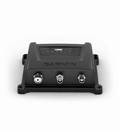
Device Ports

Connecting the Device to Power
![]()
When programmed with a valid MMSI number, this device allows you to transmit AIS signals with vessel position data. This device is meant to enhance situational awareness and may not prevent vessel collisions in all circumstances. It is your obligation to be aware of your surroundings and to ensure safe operation of the vessel.
![]()
After installing the device and programming a valid vessel MMSI number, you can temporarily revert to the default silent mode (only receives, does not transmit) using a toggle switch (not included) (Connecting the Device to Power, page 2). While operating in silent mode, the device does not transmit AIS signals.
Four wires (red, black, green, and yellow) provide the basic power connection.
- Route the wiring harness from the device POWER (and NMEA 0183) port to the battery .
- Connect the red wire to the positive (+) battery terminal.
- Connect the black wire to the power ground on the negative (-) battery terminal.
- Connect the green wire to the power ground with a switch (not included) between the green wire and power ground, to provide a toggle , switch to revert to the default silent mode (optional).
- Complete an action, based on the network type:
- In a NMEA 0183 system, connect the yellow wire (Accessory On) to the power ground, and install a switch (not included) between the yellow wire and the power ground.
NOTICE
Turning off the switch prevents the device from draining the battery when the engine is off. - In a NMEA 2000 system, the device automatically powers on and off with the system, and you do not need to connect the yellow Accessory On wire.
- In a NMEA 0183 system, connect the yellow wire (Accessory On) to the power ground, and install a switch (not included) between the yellow wire and the power ground.
Connecting a VHF Antenna
To transmit and receive AIS information, the AIS 800 must be connected to external VHF antenna (not included). The device has an internal antenna splitter that allows VHF and AIS to share a single antenna.
- Mount the VHF antenna (sold separately) according to the installation instructions provided with the antenna.
NOTE: You can purchase a VHF antenna extension cable. Go to buy.garmin.com or contact your Garmin dealer. - Connect the VHF antenna cable to the VHF ANT port on the Garmin AIS 800 device.
NMEA 2000 Device Connections
NOTICE
If you are installing a NMEA 2000 power cable, you must connect it to the boat ignition switch or through another in-line switch. NMEA 2000 devices will drain your battery if the NMEA 2000 power cable is connected to the battery directly.
In a NMEA 2000 system, the device automatically powers on and off with the system, and connecting the yellow Accessory On wire is not necessary (Connecting the Device to Power, page 2).
If you are unfamiliar with NMEA 2000, you should read the “NMEA 2000 Network Fundamentals” chapter of the Technical Reference for NMEA 2000 Products. Go to garmin.com/manuals/nmea_2000.

- Compatible NMEA 2000 chartplotter or other device
- Garmin AIS 800 device
- Ignition or in-line switch
- NMEA 2000 power cable
- NMEA 2000 drop cable
- 12 Vdc power source
- NMEA 2000 terminator or backbone cable
- NMEA 2000 T-connector
- NMEA 2000 terminator or backbone cable
NMEA 0183 Device Connections
This diagram illustrates two-way connections for both sending and receiving data. You can also use this diagram for one-way communication.
To receive information from a NMEA 0183 device, refer to items and when connecting the Garmin device.
To transmit information to a NMEA 0183 device, refer to items and when connecting the Garmin device.
For either NMEA 2000 or NMEA 0183 systems, refer to item when making the basic power connections (Assigning Data to the Device, page 1), (Connecting the Device to Power, page 2).

Status LEDs


- Connecting the green wire to the power ground with a switch (not included) provides a toggle to temporarily revert to silent mode (receives only, does not transmit).
- In NMEA 0183 systems, use the switch to power off the device when the boat engine is off, to avoid draining the battery.
Connecting the Device to a Remote GPS Antenna
This device must receive GPS information for proper functionality. The device includes an internal GPS antenna. If your mounting location does not provide good GPS reception, you can install a remote GPS antenna (not included) and connect it to the device.
- Follow the instructions provided with your external GPS antenna to install it on your boat correctly.
- Route the GPS antenna cable to the back of your device, away from sources of electrical interference.
- Connect the GPS antenna cable to the GPS ANT port on your device.
Appendix
Specifications

NMEA 2000 PGN Information
Transmit
![]()
![]()
Receive

NMEA 0183 Sentences Supported

Testing for Interference from LED Lights
LED lighting from sources such as navigation lights, searchlights, floodlights, interior and exterior lights, and adornments can interfere with your Garmin AIS 800 device. Radio interference can cause poor reception, jam radio signals, and create a safety hazard in emergency situations. You should test for LED interference before mounting the VHF antenna.
NOTICE
If your LED lights interfere with the Garmin AIS 800 device, you must mount the VHF antenna farther away from the LED lights, or use non-jamming lights.
- Turn off all LED lights.
- Turn on your chartplotter and Garmin AIS 800 device.
- Observe the moving AIS targets on the chartplotter screen for at least one minute.
- Turn on all LED lights.
- Observe the moving AIS targets on the chartplotter screen for at least one minute.
If most of the moving AIS targets disappear from the screen, the LED lights interfere with the Garmin AIS 800 device reception.
¹ The device withstands incidental exposure to water of up to 1 m for up to 30 min. For more information, go to www.garmin.com/waterrating.
© 2018 Garmin Ltd. or its subsidiaries
Garmin® and the Garmin logo are trademarks of Garmin Ltd. or its subsidiaries, registered in the USA and other countries. These trademarks may not be used without the express permission of Garmin.
NMEA® , NMEA 2000 ® , and the NMEA 2000 logo are registered trademarks of the National Marine Electronics Association.