
HAMPTON BAY Fernlake Steel

Important Safety Instructions
WARNING: This dining chair was made for the explicit purpose of providing outdoor functions and is not to be used as a toy.
This product is intended for normal outdoor use; however, the manufacturer recommends storing and / or covering this product when any formidable/severe weather is approaching.
WARNING: The weight limit for the chairs is 250 lbs (113.39 kg) for each seat.
READ ALL INSTRUCTIONS BEFORE USE
To reduce the risk of injury to persons:
- Close supervision is necessary when this product is used by or near children, or disabled persons, if applicable.
- Do not move the chairs while the chairs are occupied. Failure to obey this caution could result in injury.
- Use this product only for its intended use as described in these instructions. Do not use attachments not recommended by the manufacturer.
- Do not rock in the chair as you may fall and cause serious injury.
- Please keep children out of the assembly area before assembly
3 YEAR LIMITED WARRANTY
WHAT IS COVERED
We warrant the frames to be free of manufacturing defects to the original purchaser for three years.
WHAT IS NOT COVERED
It remains the customer’s responsibility for freight and packaging charges to and from our service center. This warranty does not cover commercial use. We reserve the right to make substitutions with similar merchandise if the model in question is no longer in production.
Contact the Customer Service Team at 1-855-HD-HAMPTON or visit www.HamptonBay.com
Pre-Assembly
PLANNING ASSEMBLY
Read all instructions before assembly.
To avoid damaging this product, assemble it on a soft, non-abrasive surface such as carpet or cardboard.
NOTE: More than one person may be required to assemble this product.
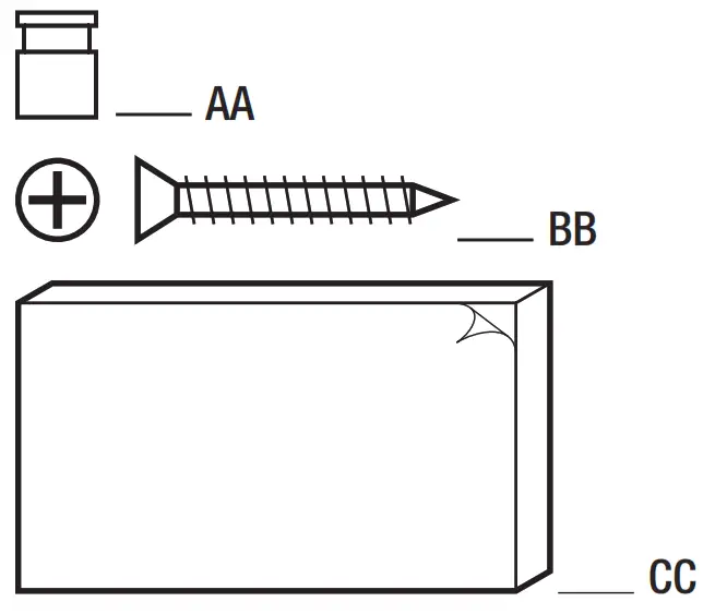
HARDWARE INCLUDED
NOTE: Hardware not shown to actual size.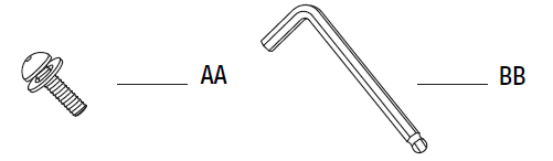
| Part | Description | Quantity |
| AA | M6x20 combination bolt | 24+1 |
| BB | Hex wrench | 1 |
CHAIR PACKAGE CONTENTS
| Part | Description | Quantity |
| A | Seat | 2 |
| B | Front Leg | 4 |
| C | Left Rear Leg | 2 |
| D | Right Rear Leg | 2 |
| E | Seat Cushion | 2 |
Chair Assembly
ATTACHING THE FRONT LEG, LEFT REAR LEG AND RIGHT REAR LEG TO THE SEAT
- Place the seat (A) upside down on a soft surface.
- Attach the front leg (B), left rear leg (C), and right rear leg (D) to the seat (A) using M6x20 combination bolt (AA).
NOTE: Loosely tighten all bolts using the hex wrench (BB).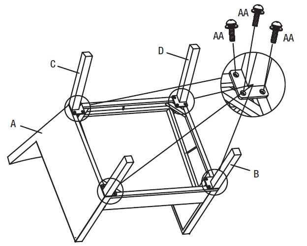
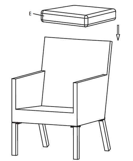
TIGHTENING ALL BOLTS AND PUT THE SEAT CUSHION ON THE CHAIR
- Once all of the bolts are in place, fully tighten all the bolts using hex wrench (BB).
- Turn the chair right side up.
- Put the seat cushion (E) on the chair.
- Ensure all connections are secure before use.
Care and Cleaning
- For best results, clean the frame and cushions with a damp cloth and dry thoroughly. This will help prevent mildew by removing dirt particles that may accumulate.
- Do not clean with abrasive materials, bleach, or solvents.
- Store the chair in a dry, sheltered place when not in use.
- Keep the chair away from extreme heat, freezing conditions, and inclement weather such as rain, hail, sleet, snow, or wind.

USE AND CARE GUIDE
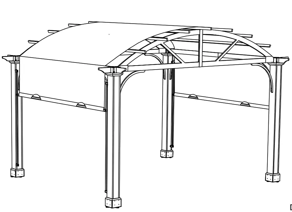
10X12 LONGFORD PERGOLA
Item# 1004 662 155/1004 649 550/1004 649 549/ 1004 547 739
Model #A106003600
Questions, problems, missing parts? Before returning to the store,
call Hampton Bay Customer Service
8 a.m. – 7 p.m., EST, Monday-Friday, 9 a.m. – 6 p.m., EST, Saturday
1-855-HD-HAMPTON
HAMPTONBAY.COM
THANK YOU
We appreciate the trust and confidence you have placed in Hampton Bay through the purchase of this Pergola. We strive to continually create quality products designed to enhance your home. Visit us online to see our full line of products available for your home improvement needs. Thank you for choosing Hampton Bay!
Safety Information
- At least 2 persons are required for this assembly.
- Some parts may contain sharp edges. Wear protective gloves.
- When assembling and using this product, basic safety precautions should always be followed to reduce the risk of personal injury and damage to equipment. Please read all instructions before assembly and usage.
NOTICE: For outdoor use only.
 WARNING: Keep all flame and heat sources away from this pergola fabric. This pergola is made with fabric that meets CPAI-84 specifications for flame resistance. It is not fireproof. The fabric will burn if left in continuous contact with any flame source. The application of any foreign substance to the pergola fabric may render the flame-resistant properties ineffective.
![]() CAUTION: Do not climb on top of the pergola. Falling off the pergola can result in serious injury, possibly even death.
CAUTION: Do not climb on top of the pergola. Falling off the pergola can result in serious injury, possibly even death.
![]() DANGER: This unit is heavy! Do not assemble this item alone.
DANGER: This unit is heavy! Do not assemble this item alone.
WARNING: While this pergola is manufactured to withstand winds through only the supplied ground stakes, in areas subject to frequent severe weather, securing the pergola to a deck, concrete patio or footings should be considered. Snow must be cleared off regularly during snowy days. Remove the snow at the top when it is thicker than 4 inches. In order to avoid damage, use a plastic snow rake to remove excess snow and ice buildup from the roof and keep away from falling debris.
Warranty’
2 YEAR WARRANTY
WHAT IS COVERED
This limited warranty is extended to the original purchaser and applies to defects in materials and workmanship of your item provided the item is maintained with care and used only for personal, residential purposes. The item is warranted to be free from defects in material or workmanship for a period of 2 years.
WHAT IS NOT COVERED
We do not reimburse for transportation of delivery costs or compensate the individual or any outside party for assembling or disassembling the product. Contact the Customer Service Team at 1-855-HD-HAMPTON or visit HAMPTONBAY.COM.
Production Number: 2020BPCN10
Pre-Assembly
IMPORTANT
Requires at least 2 persons for the installation work. Approximate installation time:2~3 hours.
PLANNING ASSEMBLY
Before beginning the assembly of this product, make sure all parts are present. Compare parts with the Hardware Included and Package Contents lists. If any part is missing or damaged, do not attempt to assemble the product. Contact customer service for replacement parts.
HARDWARE INCLUDED
![]() NOTE: Hardware not shown to actual size.
NOTE: Hardware not shown to actual size.
| Part | Part Number | Description | Quantity | Additional Hardware |
| AA | H36035C31 | M6 X 35 Screw | 40 | 2 |
| BB | H36060C31 | M6 X 60 Screw | 16 | 1 |
| CC | H40080C31 | M6 X 80 Screw | 8 | 1 |
| DD | H11040B31 | M5 X40 Screw | 64 | 4 |
| EE | H02045C11 | M6 X 45 Bolt | 16 | 1 |
| FF | H02020C11 | M6 X 20 Bolt | 8 | 1 |
| GG | H02040C11 | M6 X 40 Bolt | 4 | 1 |
| HH | H11025B11 | M5 X 25 Screw | 40 | 2 |
| II | H02055C11 | M6 X 55 Bolt | 14 | 1 |
| JJ | H09012C11 | M6 X 12 Bolt | 4 | 1 |
| KK | H19001C11 | M6 Flat Washer | 138 | 7 |
| LL | P12401A01001 | ¢8*180 Stake | 8 | 0 |
| MM | H06015C11 | M6 X 15 Bolt | 36 | 2 |
| NN | P15601A27000 | Sticker | 1 | 0 |
| Z1 | H00001C12 | M6 Wrench | 2 | 0 |
| Z2 | H00002C12 | M6 Allen key | 1 | 0 |
PACKAGE CONTENTS
| Part | Part Number | Description | Quantity |
| 1 | P000200217 | Post | 4 |
| 2 | P006100082 | Base Cover | 16 |
| C | P000100135 | Base | 4 |
| D | P000300031 | Cover | 4 |
| E | P005000197 | Arc Support | 8 |
| F1 | P000400490 | Right Curved Frame | 2 |
| F2 | P000400491 | Left Curved Frame | 2 |
| G1 | P000400488 | Right Beam | 2 |
| G2 | P000400489 | Left Beam | 2 |
| H | P005600116 | Decorative Profile | 8 |
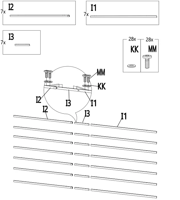
| I1 | P000600665 | Right Cross Beam | 7 |
| I2 | P000600666 | Left Cross Beam | 7 |
| I3 | P000500563 | Cross Beam Connector | 7 |
| J | P005700187 | Guide Tube | 4 |
| K | P005700564 | Guide Tube Connector | 8 |
| L1 | P005700188 | Canopy Tube 1 | 2 |
| L2 | P005700189 | Canopy Tube 2 | 2 |
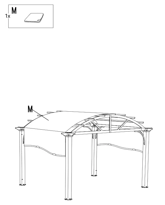
| M | P001100279 | Canopy | 1 |
| N | P000500562 | Connector | 4 |
Attaching the Base
Attach the Base (C) to the Post (01) using screws (HH). It is suggested to pre-drill holes for easier installation of the base.
Insert the Cover (D) into the top of the Post (01), but don’t assemble.
![]() NOTE: To avoid destroying the finish, do not put the parts on the ground directly.
NOTE: To avoid destroying the finish, do not put the parts on the ground directly.
Connecting the Beams and Connector
Connect the Beams (G1&G2) with the Connector (N) using bolts (MM) and flat washers (KK).
![]() NOTE: To avoid destroying the finish, do not put the parts on the ground
NOTE: To avoid destroying the finish, do not put the parts on the ground
Connecting the Curved Frames and Connector
![]() NOTE: To avoid destroying the finish, do not put the parts on the ground directly.
NOTE: To avoid destroying the finish, do not put the parts on the ground directly.
Connecting the Curved Frames and Posts
Attach the Curved frames (F1&F2) with the Post (01) using screws (AA) and flat washers (KK).
![]() NOTE: Pay close attention to the hole placement to ensure proper assembly. Also, pay attention to the direction of the curved frames.
NOTE: Pay close attention to the hole placement to ensure proper assembly. Also, pay attention to the direction of the curved frames.
Attaching the Beams
Attach the beams (G1&G2) to the post (01) using screws (AA) and flat washers (KK).
![]() NOTE: Ensure post is oriented properly before installing beams, inside of posts must have holes for canopy guide tube.
NOTE: Ensure post is oriented properly before installing beams, inside of posts must have holes for canopy guide tube.
Attaching the Decorative Profile
Attach the decorative profiles (H) to the post (01) using screw (AA) and washer (KK). Attach the Cover (D) to the post (01) using screw (HH).
It is recommended to predrill holes to install the Cover (D).
![]() NOTE: To avoid destroying the finish, do not put the parts on the ground directly.
NOTE: To avoid destroying the finish, do not put the parts on the ground directly.
Attaching the Arc Support
Attach the arc support (E) to the curved frames (F1&F2), beams (G1&G2) and post (01) using bolts (EE), screws (BB) and flat washers (KK).
![]() NOTE: To avoid destroying the finish, do not put the parts on the ground directly. Make sure the angle between the curved frame and post is 90°when attaching the Support, the triangular rule can be used if necessary.
NOTE: To avoid destroying the finish, do not put the parts on the ground directly. Make sure the angle between the curved frame and post is 90°when attaching the Support, the triangular rule can be used if necessary.
Connecting the Crossbeam
Connect the cross beam (I1&I2) with cross beam connector (I3) using bolts (MM) and flat washers (KK)
![]() NOTE: To avoid destroying the finish, do not put the parts on the ground directly.
NOTE: To avoid destroying the finish, do not put the parts on the ground directly.
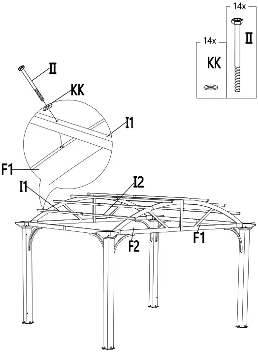
Attaching the Cross Beams
Attach the cross beams (I1&I2) and curved frames (F1&F2) using bolts (II) and flat washers (KK).
![]() NOTE: To avoid destroying the finish, do not put the parts on the ground directly.
NOTE: To avoid destroying the finish, do not put the parts on the ground directly.
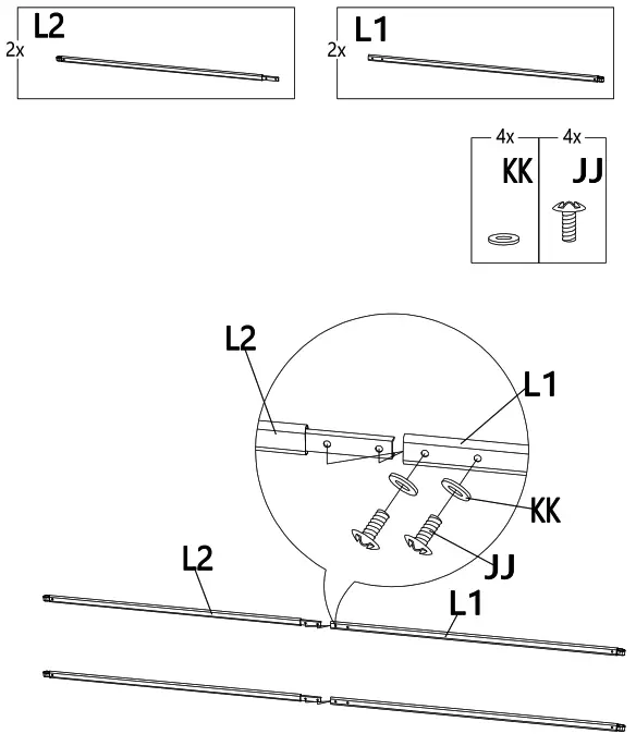
Connecting the Canopy Tube
Connect the canopy tube 1 (L1) with the canopy tube 2 (L2) using bolt (JJ) and flat washer (KK).
![]() NOTE: To avoid destroying the finish, do not put the parts on the ground directly.
NOTE: To avoid destroying the finish, do not put the parts on the ground directly.
Cover the canopy (M) on the pergola.
![]() NOTE: To avoid destroying the finish, do not put the parts on the ground directly.
NOTE: To avoid destroying the finish, do not put the parts on the ground directly.
Inserting the Canopy Tube
Insert the canopy tubes (L1&L2) into the canopy (M).
![]() NOTE: To avoid destroying the finish, do not put the parts on the go directly.
NOTE: To avoid destroying the finish, do not put the parts on the go directly.
Inserting the Guide Tube
Insert the Guide tube (J) into the Canopy tubes (L1&L2). Then connect the Guide tube (J) and Guide tube connector (K) with Post (01) using screws (CC). Then secure the guide tube connect (K) to the post (01) using a screw (HH). For easier installation, it is recommended to predrill holes for screw bolt (HH) to make the Guide tube connector (K) level.
NOTE: To avoid destroying the finish, do not put the parts on the ground directly. You may need to slide the canopy back and forth a few times to ensure it is square.
Securing the pergola
Secure the pergola on the ground with stakes (LL)
It is recommended for anchoring on wood or concrete surface for more stability using setscrew (Purchased separately).
![]() NOTE: To avoid destroying the finish, do not put the parts on the ground directly.
NOTE: To avoid destroying the finish, do not put the parts on the ground directly.
Attach the base cover (02) and post (01) using screws (DD).
![]() NOTE: To avoid destroying the finish, do not put the parts on the ground directly.
NOTE: To avoid destroying the finish, do not put the parts on the ground directly.
Apply the stickers on the pre-drill holes
Apply the stickers (NN) to cover the pre-drill holes on the Posts (01) if you choose, but not required.
![]() NOTE: To avoid destroying the finish, do not put the parts on the ground directly.
NOTE: To avoid destroying the finish, do not put the parts on the ground directly.
Care and Cleaning
- Steel components for this gazebo are treated with rust-inhibiting paint that protects it from rusting. However, due to the nature of steel, surface oxidation (rusting) will occur if these protective coatings are scratched. This is not a defect and thus not covered by the warranty. To minimize this condition, it is recommended to use care when assembling and handling the product to prevent scratching the paint. Should any scratching or damage occur, it is recommended to cover the scratch immediately with rust-inhibiting paint (not included). Surface rust can also be easily removed with a very light application of regular cooking oil. If surface oxidation (rusting) occurs and if no measure is taken to prevent this, the oxidation may start dripping onto the deck or patio and caused damaging stains, which may be difficult to remove. This can be prevented if the above-mentioned measures are taken to keep the product from oxidizing.
- Do not use bleach, acid, or other abrasive cleaners on the roof or frame parts.
- Keep instruction manual for future reference.
- Keep the original packaging to store the gazebo.
- Remove canopy during bad weather and windy conditions.
- When not in use, store in a cool, dry area.
Questions, problems, missing parts? Before returning to the store, call Hampton Bay Customer Service
8 a.m. – 7 p.m., EST, Monday-Friday, 9 a.m. – 6 p.m., EST, Saturday
1-855-HD-HAMPTON
HAMPTONBAY.COM
Retain this manual for future use.
HAMPTON BAY THERMOSTATIC REMOTE CONTROL
Pre-Installation
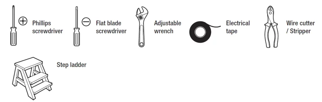
TOOLS REQUIREDPhillips
- screwdriver
- Flathead screwdriver
- Adjustable wrench
- Electrical tape

- Wirecutter
- Step ladder
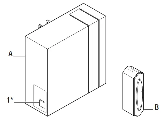
PACKAGE CONTENTS
IMPORTANT: This product and/or components are governed by one or more of the following U.S. Patents: 5,947,436; 5,988,580; 6,010,110; 6,046,416, 6,210,117 and other patents pending.
| Part | Description | Quantity |
| A | Transmitter | 1 |
| B | Receiver | 1 |
| C | Plastic wire connector | 5 |
| D | AAA battery (1.5 V) | 2 |
| E | Silicone rubber plug | 1 |
| F | Wall cradle | 1 |
| G | Wall cradle screw | 2 |
| H | Plastic anchor | 2 |
Installation
Setting the codes on the remote control and receiver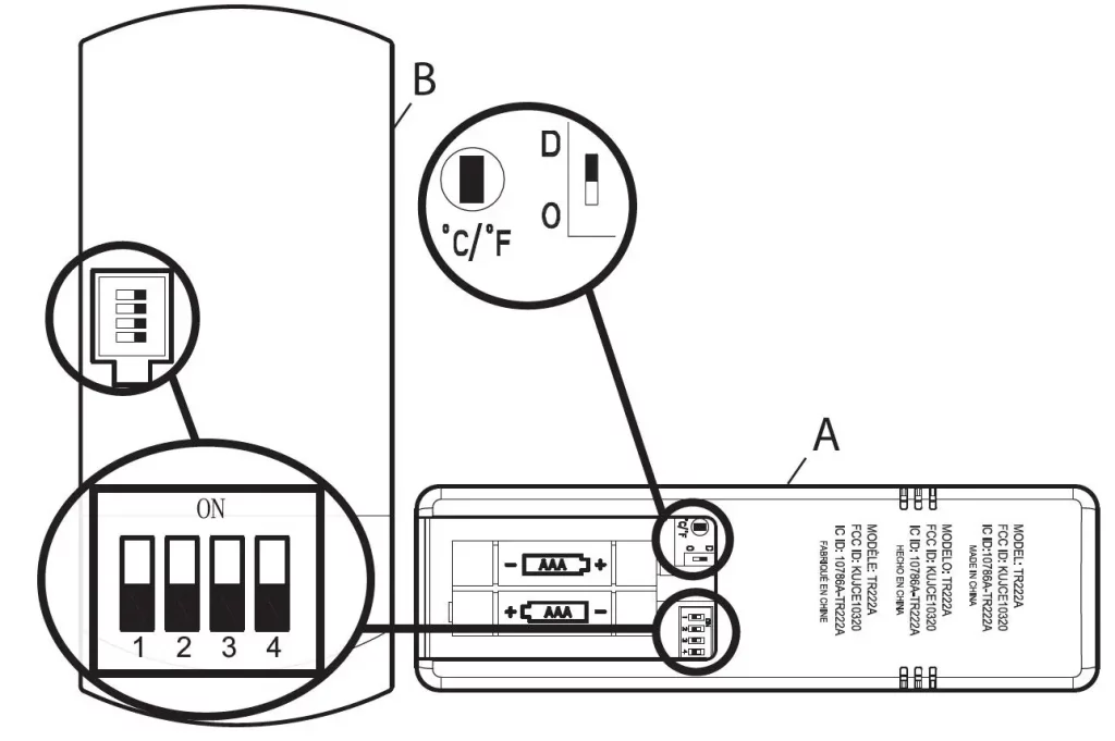
NOTE
- The frequencies on your receiver and hand unit have been preset at the factory. Before installing the receiver, make sure the dip switches on the receiver and hand unit are set to the same frequency. The dip switches on the hand unit are located inside the battery compartment.
- The battery will weaken with age and should be replaced before leaking takes place as this will damage the hand unit. Dispose of the used battery properly and keep the battery out of the reach of children.
- It is imperative that the code used for both transmitter and receiver is exactly the same, otherwise remote controller will not work.
Setting the Code on the Remote
- Remove the battery cover on the back of the remote control (A) by pressing firmly on the arrow and sliding the cover off.
- Slide the code switches to your choice of either up or down. The factory setting is up.
- From the factory, the remote displays °F, press the °C/°F button once to change the settings to °C.
- For fans with dimmable bulbs, slide the dip switch O/D to the position marked “D”, if you are not using dimmable bulbs slide the dip switch to the “O” position.
- Install 2 AAA batteries (included).
- Replace the battery cover on the remote control
Setting the Code on the Receiver
- Slide the code switches on the receiver (B) to the same positions as set on the remote control (A).
- Insert the silicone rubber stopper (E) into the hole on the receiver (B) to cover the dip switches.
Controller Model: TR222A
Operation
Operating the remote control
- Press and release the button to turn the fan and the lights on or off.
- Press and hold the button for 3 seconds to use the “walk away from time delay”; this will activate the light for 30 seconds (if you are using dimmable bulbs the light will be activated at 50% brightness).
- Press and release 1 time – turn the fan on high speed.
- Press and release 2 times – turns the fan on medium speed.
- Press and release 3 times – turns the fan on low speed.
- Press and release 4 times – turns the fan off.
- Press and hold this button for 3 seconds to enable Comfort BreezeTM; this will change your fan speed randomly, simulating a relaxing breeze. To cancel this feature press or .
- While the fan is on press 1 time – turn on a 2-hour run timer.
- While the fan is on press 2 times – turn on a 4-hour run timer.
- While the fan is on press 3 times – turn on an 8-hour run timer.
- This setting allows the fan to automatically turn on and off at a previously set room temperature.
- Press 1 time to adjust the set temperature + 1°, and press and hold to raise the set temperature multiple degrees.
- Press 1 time to adjust the set temperature – 1°, press and hold to lower the set temperature multiple degrees.
- The digital display shows the set temperature when or is pressed.
- Press and release the button to turn the light on or off.
- If you are using dimmable bulbs and you have previously set the O/D dip switch in your remote to the “D” position, press and hold the button to activate the dimmer function
Mounting the remote control holder
- Slide the screw cover plate up to remove it from the wall cradle.
- Position the wall cradle in the desired position and attach it to the wall using the included wall cradlescrews.
- Slide the screw cover plate back onto the wall cradle to conceal the screws.
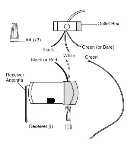
Installing the receiver
- WARNING: To reduce the risk of fire or electric shock, remember to disconnect power. The electrical wiring must meet all local and national electrical code requirements. The electrical source and fan must be 110/120 volt, 60Hz. Do not use this product in conjunction with any variable wall control. An incorrect wire connection can damage this receiver.
- CAUTION: If other fan wires are a different color, have this unit installed by a licensed electrician.
CAUTION: Do not immerse in water. Do not pull on or cut leads shorter. Do not drop or bump the unit. - NOTE: The ceiling fan must be set at HIGH speed and the light kit (if installed) should be set to the ON position.
NOTE: The battery will weaken with age and should be replaced before leaking takes place as this will damage the transmitter. Dispose of used battery properly. Keep the remote out of the reach of children.- Position the house supply wires (AAA) to one side of the slide-on mounting bracket (A); position the fan wires (BBB) to the opposite side.
- Insert the narrow end of the receiver (as shown, flat side towards the ceiling) into the slide-on mounting bracket until it rests on top of the ball/downrod assembly.
Wiring the receiver to the household wiring
- WARNING: To avoid possible electrical shock, turn the electricity off at the main fuse box before wiring. If you feel you do not have enough electrical wiring knowledge or experience, contact a licensed electrician.
- WARNING: Each wire not supplied with this fan is designed to accept up to one 12-gauge house wire and two wires from the fan. If you have larger than 12-gauge house wiring or more than one house wire to connect to the fan wiring, consult an electrician for the proper size wire nuts to use.
- IMPORTANT: Use the wire connecting nuts (C) supplied with your fan. Secure the connectors with electrical tape and
ensure there are no loose strands or connections.- Spread the wires apart so that the green and white wires are on one side of the outlet box and the black wire is on the other side.
- Connect the green fan wires to the household ground wire (this may be a green or bare wire) using a wire connecting nut (C).
- Connect the receiver black (or red) wire to the household black (hot) wire using a wire connecting nut (C).
- Connect the receiver white wire to the household white wire (neutral)
- wire using a wire connecting nut (C).
- Secure each wire connecting the nut using electrical tape.
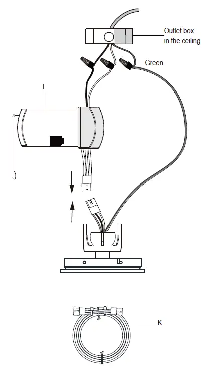
Wiring the fan to the receiver
- IMPORTANT: Use the wire connecting nuts (C) supplied with your fan. Secure the connectors with electrical tape and ensure there are no loose strands or connections.
- Connect the fan motor white wire to the receiver white wire using a wire connecting nut (C).
- Connect the fan motor black wire to the receiver black wire using a wire connecting nut (C).
- Connect the fan motor blue wire to the receiver blue wire using a wire connecting nut (C).
- Secure each wire connecting the nut using electrical tape.
- Turn the wire connecting nut (C) upward and push the wiring into the outlet box (MM).
Troubleshooting
| Problem | Solution |
| The fan will not start. | □ Check the main and branch circuit fuses or breakers.
□ Check to make sure the wall switch is in the on position if applicable. □ Check the line wire connections to the fan and switch wire connections in the switch housing. □ Check the battery in the transmitter. □ Ensure you are in the normal range of 10-20 ft (3-6m). □ Ensure the dip switch settings are the same on the transmitter and receiver. □ Remember to turn off the power supply before checking the dip switch settings. |
FCC Statment
This equipment has been tested and found to comply with the limits for a Class B digital device, pursuant to Part 15 of the FCC Rules. These limits are designed to provide reasonable protection against harmful interference in a residential installation. This equipment generates, uses, and can radiate radio frequency energy and, if not installed and used in accordance with the instructions, may cause harmful interference to radio communications. However, there is no guarantee that interference will not occur in a particular installation. If this equipment does cause harmful interference to radio or television reception, which can be determined by turning the equipment off and on, the user is encouraged to try to correct the interference by one or more of the following measures:
- Reorient or relocate the receiving antenna.
- Increase the separation between the equipment and receiver.
- Connect the equipment into an outlet on a circuit different from that to which the receiver is connected.
- Consult the dealer or an experienced radio/TV technician for help.
- CAUTION: Any changes or modifications not expressly approved by the grantee of this device could void the user’s authority to operate the equipment.
- FCC ID: KUJCE10320: This device complies with Part 15 of the FCC Rules. Operation is subject to the following two conditions:
- This device may not cause harmful interference
- this device must accept any interference received, including interference that may cause undesired operation.
![]()
USE AND CARE GUIDE
WIRELESS PLUG-IN DOORBELL KIT
Illustrations may vary from the actual unit.
THANK YOU
We appreciate the trust and confidence you have placed in Hampton Bay through the purchase of this wireless doorbell kit. We strive to continually create quality products designed to enhance your home. Visit us online to see our full line of products available for your home improvement needs. Thank you for choosing Hampton Bay!
Safety Information
PRECAUTIONS
- Please read and understand this entire manual before attempting to assemble, install, or operate this doorbell.
- All electrical work must be in accordance with national and local electrical codes. If in doubt, consult a qualified electrician.
 WARNING: To prevent possible SERIOUS INJURY or DEATH never allow small children near batteries. If the battery is swallowed, immediately notify a doctor.
WARNING: DO NOT DISPOSE OF BATTERIES IN FIRE. BATTERIES MAY EXPLODE OR LEAK.
WARNING: Risk of fire. Do not plug the doorbell into a power inverter.
![]() NOTE: The push-button and doorbell come synced from the factory. The range of the wireless doorbell can vary with location, temperature, and battery condition.
NOTE: The push-button and doorbell come synced from the factory. The range of the wireless doorbell can vary with location, temperature, and battery condition.
This device complies with Part 15 of the FCC Rules. Operation is subject to the following two conditions: (1) this device may not cause harmful interference, and (2) this device must accept any interference received, including interference that may cause undesired operation.
Warning: Changes or modifications to this unit not expressly approved by the party responsible for compliance could void the user’s authority to operate the equipment.
Note: This equipment has been tested and found to comply with the limits for a Class B digital device, pursuant to part 15 of the FCC Rules. These limits are designed to provide reasonable protection against harmful interference in a residential installation. This equipment generates, uses, and can radiate radio frequency energy and, if not installed and used in accordance with the instructions, may cause harmful interference to radio communications. However, there is no guarantee that interference will not occur in a particular installation. If this equipment does cause harmful interference to radio or television reception, which can be determined by turning the equipment off and on, the user is encouraged to try to correct the interference by one or more of the following measures:
- Reorient or relocate the receiving antenna.
- Increase the separation between the equipment and receiver.
- Connect the equipment into an outlet on a circuit different from that to which the receiver is connected.
- Consult the dealer or an experienced radio/TV technician for help.
This device contains license-exempt transmitter(s)/receiver(s) that comply with Innovation, Science, and Economic Development Canada’s license-exempt RSS(s). Operation is subject to the following two conditions:
- This device may not cause interference.
- This device must accept any interference, including interference that may cause undesired operation of the device.
FCC Responsible Party Name: HeathCo LLC
Address: 2445 Nashville Road, Bowling Green, KY 42101 U.S.A.
Telephone Number: 800-858-8501
Warranty
3-YEAR LIMITED WARRANTY
WHAT IS COVERED
This product is guaranteed to be free of factory defective parts and workmanship for a period of 3 years from the date of purchase. A purchase receipt is required for all warranty claims.
WHAT IS NOT COVERED
This warranty does not include expendable items (such as light bulbs, batteries, etc.), repair service, adjustment, and calibration due to misuse, abuse, or negligence. Unauthorized service or modification of the product or of any furnished component will void this warranty in its entirety. This warranty does not include reimbursement for inconvenience, installation, setup time, loss of use, unauthorized service, or return shipping charges. This warranty is not extended to other equipment and components that a customer uses in conjunction with this product. The manufacturer reserves the right to discontinue products and to change specifications at any time without incurring any obligation to incorporate new features in products previously sold.
Contact the Customer Service Team at 1-844-760-3644 or visit www.hamptonbay.com.
Pre-Installation
PLANNING INSTALLATION
Before installing the wireless doorbell kit, ensure that all parts are present. Compare parts with the Hardware Included and Package Contents sections. If any part is missing or damaged, do not attempt to assemble, install, or operate this wireless doorbell kit.
Estimated installation time: 30 minutes
SPECIFICATIONS
| Doorbell | Push-button | |
| Power requirements | 120 VAC, 60 Hz | Type A23 12V battery (included) |
TOOLS REQUIRED
HARDWARE INCLUDED
![]() NOTE: Hardware shown to actual size.
NOTE: Hardware shown to actual size.
| Part | Description | Quantity |
| AA | Juniper | 1 |
| BB | Screw | 2 |
| CC | Double-sided tape | 1 |
PACKAGE CONTENTS
| Part | Description | Quantity |
| A | Doorbell | 1 |
| B | Push-button | 1 |
Tune/Sync/Reset button. See Operation, step 2 – Selecting a tune or Troubleshooting for additional information.
Installation
- Installing the doorbell
□ Plug in the doorbell (A) at the desired location.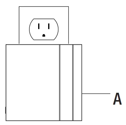
- Removing the battery tab
□ Remove the back of the push button (B) by pushing in the tab on the bottom with a small screwdriver (not included).
□ Remove the orange battery tab from the push button (B).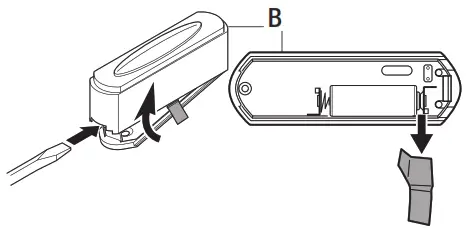
- Testing the push button and doorbell
□ Temporarily position the push button (B) where it will be mounted.
□ Press the push button (B) to verify the doorbell (A) and push button (B) work properly.
□ If the doorbell (A) does not sound, move the doorbell (A) closer to the push button (B) and test again.
 NOTE: Do not permanently mount the push button until the push button and doorbell are working properly.
NOTE: The push-button and doorbell come synced from the factory. The range of the wireless doorbell can vary with location, temperature, and battery condition.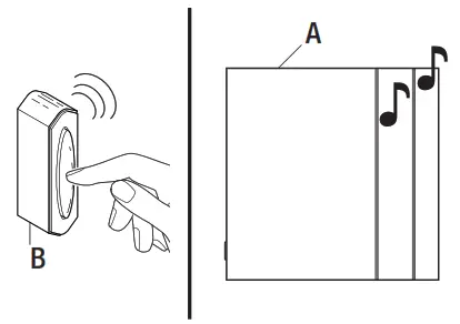
- Mounting the push button
Use either screw (BB) or double-sided tape (CC) to □ To mount with screws (BB), remove the back □ When attaching the push button (B) withNOTE:
Operation
- Setting the wireless push button
The wireless push button (B) has two options for tune selection: Play the selected “FRONT” door musical tune or play the “REAR” door designated tune (Ding).
□ The push button (B) comes from the factory with no jumper (AA) installed on the pins. This setting will play the “FRONT” door musical tune.
□ To set the push button (B) to play the “REAR” door tune (Ding), add the jumper (AA) to the pins inside the push button (B).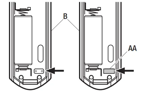
Push-button (B) set as “FRONT” door – no
jumper (AA) on the pins (Factory Default)Push-button (B) set as “REAR” door – jumper (AA) is on the pins - Selecting a tune
The doorbell (A) has different selectable tunes. The push button (B) set as the “REAR” push button (B) will only play Ding (one note tune). The push button (B) set as the “FRONT” push button (B) will play either DingDong (two-note tune) or Westminster (eight-note tune).
□ Press and release the “TUNE” button (1) on the doorbell (A) until the desired “FRONT” tune is heard.
NOTE: All doorbell models are designed to work with up to 5 wireless push buttons (sold separately).
NOTE: All doorbells are designed to play only two different tunes no matter how many push buttons are used.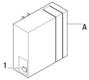
Care and Cleaning
- Use a dry cloth to clean the doorbell and push the button.
- Do not use cleaners or polishes.
- Do not use any fluids on the doorbell or push the button.
Troubleshooting
| Problem | Possible Cause | Solution |
| The doorbell does not sound. |
|
|
| The batteries seem okay, but the doorbell does not work after installation. |
|
|
| Doorbell sounds when not intended (false triggers). |
|
|
![]()
Questions, problems, missing parts?
Before returning to the store, call Hampton Bay Customer Service
8 a.m. – 5 p.m., CST, Monday – Friday
1-844-760-3644
HAMPTONBAY.COM
Retain this manual for future use.
Safety Information
READ AND SAVE THESE INSTRUCTIONS.
- To reduce the risk of electric shock, ensure the electricity has been turned off at the circuit breaker or fuse box before you begin.
- All wiring must be in accordance with the National Electrical Code ANSI/NFPA 70 and local electrical codes. Electrical installation should be performed by a qualified licensed electrician.
- The outlet box and support structure must be securely mounted and capable of reliably supporting a minimum of 35 lbs. (15.9 kg). Use only UL-listed outlet boxes marked “Acceptable for Fan Support of 35 lbs. (15.9 kg) or less.”
- The fan must be mounted with a minimum of 7 ft (2.1 m) of clearance from the trailing edge of the blades to the floor.
- Do not place objects in the path of the blades.
- To avoid personal injury or damage to the fan and other items, use caution when working around or cleaning the fan.
- After making electrical connections, spliced conductors should be turned upward and pushed carefully up into the outlet box. The wires should be spread apart with the grounded conductor and the equipment-grounding conductor on one side of the outlet box.
- All set screws must be checked and retightened where necessary before installation.
Pre-Installation
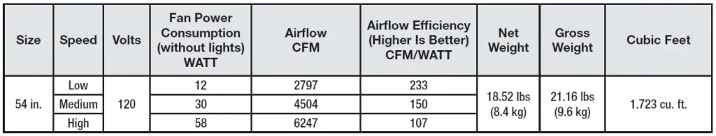
SPECIFICATIONS
TOOLS REQUIRED
Pre-Installation (continued) HARDWARE INCLUDED
Pre-Installation (continued) PACKAGE CONTENTS
MOUNTING OPTIONS
WARNING: To reduce the risk of fire, electric shock or personal injury, mount to outlet box marked “Acceptable for fan support of 35 lbs. (15.9 kg) or less”, and use screws provided with the outlet box. An outlet box commonly used for the support of lighting fixtures may not be acceptable for fan support and may need to be replaced. If in doubt, consult a qualified electrician.
If your ceiling fan does not have an existing UL-listed mounting box, then install one using the following instructions:
- Disconnect the power by removing the fuses or turning off the circuit breakers.
- Secure the outlet box directly to the building structure. Use the appropriate fasteners and materials. The outlet box and support structure must be securely mounted and capable of reliably supporting a minimum of 35 lbs. (15.9 kg). Use only UL-listed outlet boxes marked “Acceptable for fan support of 35 lbs. (15.9 kg) or less” Do not use a plastic outlet box.
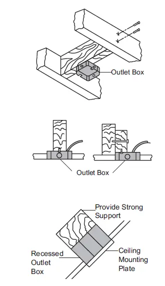
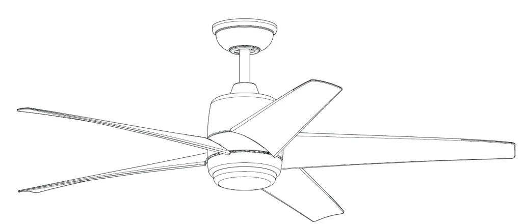
If the canopy touches the download, then remove the decorative canopy bottom cover, and turn the canopy 180° before attaching the canopy to the mounting plate. To hang your fan where there is an existing fixture but no ceiling joist, you may need an installation hanger bar as shown above (available at any Home Depot store).
Assembly – Standard Ceiling Mount
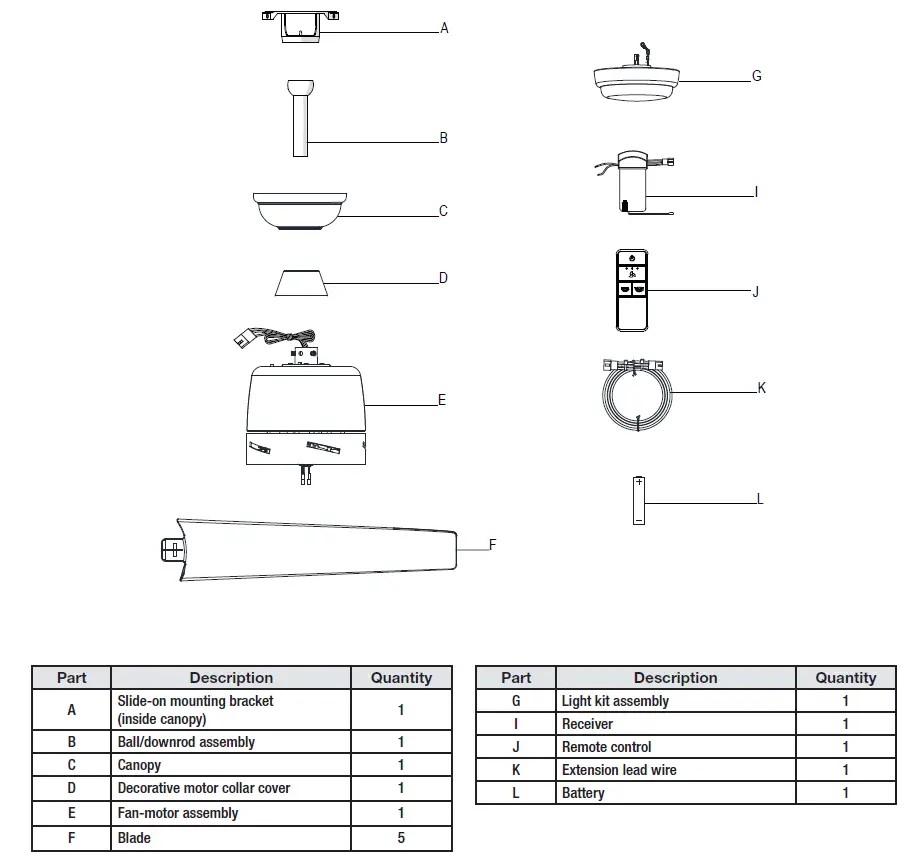
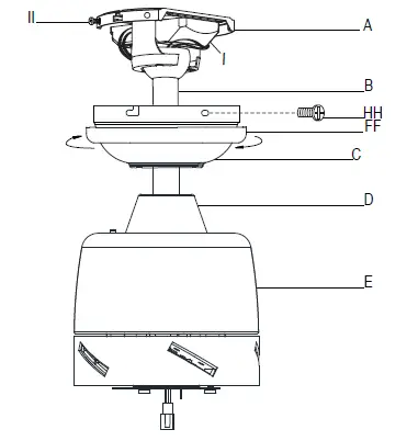
Preparing for mounting
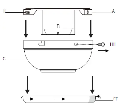
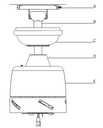
- Remove the canopy ring (FF) from the canopy (C) by turning the ring counterclockwise until it unlocks.
- Remove the mounting bracket (A) from the canopy (C) by loosening the two canopy screws (II) located in the “L-shaped” slots.
- Remove and save the two canopy screws (HH) in the round holes. This will enable you to remove the mounting bracket (A).
Routing the wires
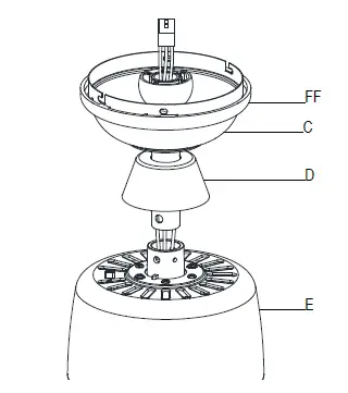
- Route the wires exiting the top of the fan motor assembly (E) through the center of the canopy ring (FF). Make sure the slots on the canopy ring (FF) are on top.
- Insert the balldownrod (B) through the canopy (C) and slide the decorative motor collar cover (D) onto the end of the ball/downrod (B). Make sure the slots on the canopy (C) are on top.
- Route the wires exiting the top of the fan motor assembly (E) through the downrod (B) as shown.
Assembling the fan
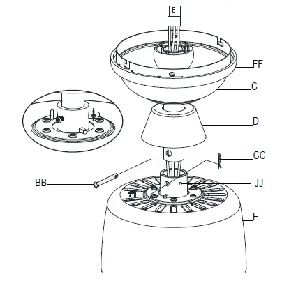
- Loosen, but do not remove, the setscrews (JJ) on the collar on top of the fan-motor assembly (E).
- Align the holes at the bottom of the ball/downrod assembly (B) with the holes in the collar on top of the fan-motor assembly (E).
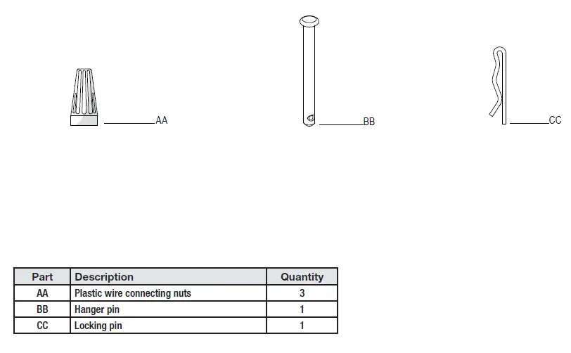
- Carefully insert the hanger pin (BB)through the holes in the collar and ball/downrod assemblyB. Be careful not to jam the hanger pin (BB) against the wiring inside the ball/ downrod assembly (B).
- Insert the locking pin (CC) through the hole near the end of the hanger pin (BB) until it snaps into its locked position.
- Re-tighten the setscrews (JJ) on the collar on top of the fan-motor assembly (E).
Assembly – Hanging the Fan
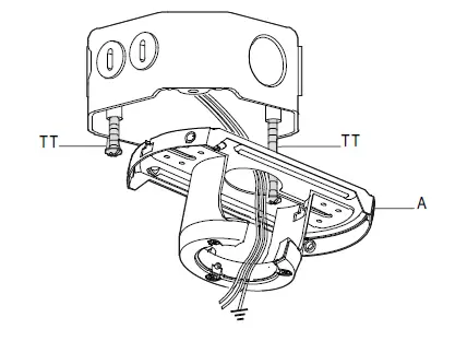
Attaching the fan to the electrical box
- Loosen the two mounting screws (TT) in the outlet box.
- Pass the 120-Volt supply wires through the center hole in the mounting bracket (A).
- Slide the mounting bracket (A) on to the mounting screws (TT) and center the mounting bracket (A) in relation to the outlet box. If necessary, use leveling washers (not included) between the slide-on mounting bracket (A) and the outlet box. The flat side of the slide-on mounting bracket (A) should face toward the outlet box, as shown.
- Securely tighten the two mounting screws (TT).
Hanging the fan
- Carefully lift the fan-motor assembly (E) up to the slide-on mounting bracket (A).
- Insert the ball portion of the ball/downrod assembly into the socket of the slide-on mounting bracket (A).
- Turn the ball/downrod (B) assembly clockwise until it is seated with the tab of the slide-on mounting bracket (A) aligned with the slot in the ball.
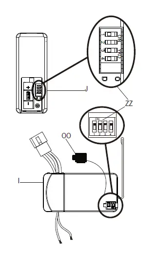
Setting the code on the remote control and receiver
- Remove the remote control (J) battery cover by pressing firmly on the arrow and sliding the cover off.
- Slide the dip switches (ZZ) to your choice of either up or down. The factory setting is up.
- Slide the dip switches (ZZ) on the receiver (I) to the same position as set on the remote control (J).
- Install the A23 12V battery (L).
- Replace the battery cover on the remote control (J).
- Insert the silicone rubber stopper (OO) into the hole on the receiver (I) to cover the dip switches.
Installing the receiver
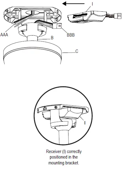
- Position the house supply wires (AAA) to one side of the slide-on mounting bracket (A); position the fan wires (BBB) to the opposite side.
- Insert the narrow end of the receiver (I) (as shown, flat side towards the ceiling) into the slide-on mounting bracket until it rests on top of the ball/downrod assembly.
Wiring the receiver to the household wiring
- Spread the wires apart so that the green and white wires are on one side of the outlet box and the black wire is on the other side.
- Connect the green fan wires to the household ground wire (this may be a green or bare wire) using a wire connecting nut (AA).
- Connect the receiver (I) black or red wire to the household black (hot) wire using a wire connecting nut (AA).
- Connect the receiver (I) white wire to the household white wire (neutral) using a wire connecting nut (AA).
- Secure each wire connecting nut using electrical tape.
Wiring the fan to the receiver
- If using the 6 in. ball downrod assembly (B) provided, wire the receiver to the fan wires by connecting the molded adaptor plug from receiver (I) with molded adaptor of the fan motor assembly (E) together.
- If you wish to use longer downrod, you can use the extension lead wire (42 in.) (K) provided by connecting the molded adaptor together.
Mounting the fan-motor assembly (standard mount)
- Align the locking slots of the canopy (C) with the two screws (II) in the mounting bracket (A). Push up to engage the slots and turn clockwise to lock in place.
- Firmly tighten the two mounting screws (II).
- Install the two canopy screws (HH) (saved from Assembly Step 1 “Prepairing for mounting”) into the holes in the canopy (C) and tighten firmly.
- Install the decorative canopy ring (FF) by aligning the ring’s slots with the screws in the canopy (C). Rotate the ring clockwise to lock in place.
Attaching the blade to the motor
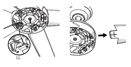
- Attach a blade (F) to the fan motor housing (E) by inserting the blade (F) into the slot in the side of the fan motor housing (E) until it stops. The locking clip (LL) will click when the blade is correctly installed. Ensure the blade is snapped into locking clip (LL) completely by pulling the fan blade away from the motor housing.
- Repeat these steps for the remaining blades (F).
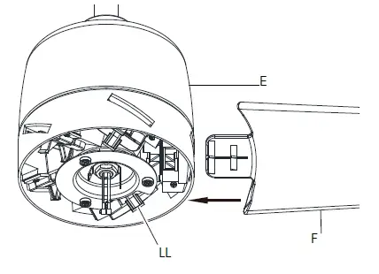
Removing the blade from the motor
- To remove the blade (F) from the motor housing (E), squeeze the tabs of the locking clip (LL) towards each other and pull the fan blade away from the motor housing.
- Repeat these steps for the remaining blades (F).
Assembly – Attaching the Accessories
Attaching the light kit fitter assembly
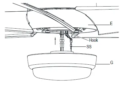
- Connect the wires from the light kit assembly (G) to the wires from the fan motor assembly (E) by connecting the molded adaptor plugs together. Carefully tuck all wires and splices into the switch cup and connect the safety cable (SS) from the light kit assembly (G) to the hook from motor assembly (E).
- Push the light kit assembly (G) up to the motor assembly (E) by aligning the magnet part of the motor assembly (E) till it is secure.
Operating Your Fan and Remote Control
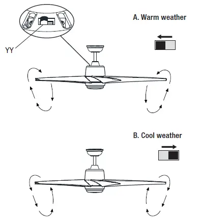
Remote Control – Your fan is equipped with a remote control to operate the speed and lights of your new ceiling fan. Speed setting for warm or cool weather depends on factors such as the room size, ceiling height, number of fans and so on. The fan is shipped from the factory with the reversing switch (YY) positioned to circulate air downward. If airflow is desired in the opposite direction, turn your fan off and wait for the blades to stop turning, then slide the reversing switch (located on the top of the motor housing) to the opposite position, and turn the fan on again. The fan blades will turn in the opposite direction and reverse airflow.
Warm weather – (Forward) A downward airflow creates a cooling effect. This allows you to set your air conditioner on a higher setting without affecting your comfort.
Cool weather – (Reverse) An upward airflow moves warm air off of the ceiling. This allows you to set your heating unit on a lower setting without affecting your comfort.
Power ON/OFF: Press and release the power button to turn the fan and light on or off.
Fan speed: LEDs on the fan speed button will illuminate to the corresponding speed.
- Press and release 1 time: turns the fan on high speed.
- Press and release 2 times: turns the fan on medium speed.
- Press and release 3 times: turns the fan on low speed.
- Press and release 4 times: turns the fan off.
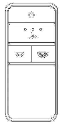
Light ON/OFF
Press and release the button to turn the light on or off. Press and hold the button to activate the dimmer function.
Correlated Color Temperature (CCT) changing
Push and release the button to cycle through the three color temperature options.
Option 1: 2700K (Warm White).
Option 2: 3000K (Soft White).
Option 3: 5000K (Daylight).
Care and Cleaning
- Because of the fan’s natural movement, some connections may become loose. Check the support connections, brackets, and blade attachments twice a year. Make sure they are secure. It is not necessary to remove the fan from the ceiling.
- Clean your fan periodically to help maintain its new appearance over the years. Do not use water when cleaning, as this could damage the motor, or the wood, or possibly cause an electrical shock. Use only a soft brush or lint-free cloth to avoid scratching the finish.
- You can apply a light coat of furniture polish to the wood for additional protection and enhanced beauty. Cover small scratches with a light application of shoe polish.
- You do not need to oil your fan. The motor has permanently-lubricated sealed ball bearings.
- To remove the blade from the motor housing, squeeze the tabs of the locking clip towards each other and pull the fan blade away from the motor housing (refer to page 11).
Troubleshooting
WARNING!
- To reduce the risk of personal injury, do not bend the blade brackets (also referred to as flanges) during assembly or after installation. Do not insert objects in the path of the blades.
- To reduce the risk of fire or electric shock, do not use this fan with any solid-state speed control device.
- To avoid possible electrical shock, turn the electricity off at the main fuse box before wiring. If you feel you do not have enough electrical wiring knowledge or experience, contact a licensed electrician.
- To reduce the risk of fire, electric shock or personal injury, mount to outlet box marked “Acceptable for fan support of 35 lbs. (15.9 kg) or less”, and use screws provided with the outlet box.
- Electrical diagrams are for reference only. If you are using a light kit, refer to the light kit instructions manual to make the electrical connections. Optional use of any light kit shall be UL-listed and marked suitable for use with this fan.
- To reduce the risk of fire or electric shock, this fan should only be used with fan speed control part no. AP-8RDL, manufactured by Dawnsun Electronic Co., LTD.
- To reduce the risk of electric shock, this fan must be installed with an isolating wall switch.
Warranty
The supplier warrants the fan motor to be free from defects in workmanship and material present at time of shipment from the factory for a lifetime after the date of purchase by the original purchaser. The supplier warrants that the light kit, excluding any glass, to be free from defects in workmanship and material at the time of shipment from the factory for a period of five years after the date of purchase by the original purchaser. The supplier also warrants that all other fan parts, excluding any glass or acrylic blades, to be free from defects in workmanship and material at the time of shipment from the factory for a period of three years after the date of purchase by the original purchaser. We agree to correct such defects without charge or at our option replace with a comparable or superior model if the product is returned. To obtain warranty service, you must present a copy of the receipt as proof of purchase. All costs of removing and reinstalling the product are your responsibility. Damage to any part, such as by accident, misuse, improper installation, or by affixing any accessories, is not covered by this warranty. Because of varying climatic conditions this warranty does not cover any changes in brass finish, including rusting, pitting, corroding, tarnishing, or peeling. Brass finishes of this type give their longest useful life when protected from varying weather conditions. A certain amount of “wobble” is normal and should not be considered a defect. Servicing performed by unauthorized persons shall render the warranty invalid. There is no other express warranty. Interline hereby disclaims any and all warranties, including but not limited to those of merchantability and fitness for a particular purpose to the extent permitted by law. The duration of any implied warranty which cannot be disclaimed is limited to the time period as specified in the express warranty. Some states do not allow a limitation on how long an implied warranty lasts, so the above limitation may not apply to you. The retailer shall not be liable for incidental, consequential, or special damages arising out of or in connection with product use or performance except as may otherwise be accorded by law. Some states do not allow the exclusion of incidental or consequential damages, so the above exclusion or limitation may not apply to you. This warranty gives specific legal rights, and you may also have other rights which vary from state to state. This warranty supersedes all prior warranties. Shipping costs for any return of product as part of a claim on the warranty must be paid by the customer.
Contact the Customer Service Team at 1-855-HD-HAMPTON or visit www.HamptonBay.com
HAMPTON BAY NCZH-G Outdoor Patio Heater Owner’s
Overview
| PART DESCRIPTION QUANTITY | ||
| A | Reflector Panel | 3 |
| B | Reflector Plate | 1 |
| FF | Reflector Stud | 3 |
| C | Head Assembly | 1 |
| D | Tabletop | 1 |
| E | Table connector | 1 |
| F | Regulator(pre-assembled in C) | 1 |
| OO | Deck Ring | 1 |
| NN | Reinforced Ring | 1 |
| G | Cylinder Housing | 1 |
| H | Post | 1 |
| I | Base | 1 |
| J | Wheel Kit | 1 |
HARDWARE CONTENTS (shown actual size)
DANGER/WARNING
If you smell gas:
- Shut off gas to the appliance.
- Extinguish any open flame.
- If odor continues, keep away from the appliance and immediately call your gas supplier or fire department. Do not store or use gasoline or other flammable vapors and liquids in the vicinity of this or any other appliance. An LP-cylinder not connected for use shall not be stored in the vicinity of this or any other appliance.
- CARBON MONOXIDE HAZARD This appliance can produce carbon monoxide which has no odor. Using it in an enclosed space can kill you. Never use this appliance in an enclosed space such as a camper, tent, car or home.
- Improper installation, adjustment, alteration, service or maintenance can cause property damage, injury or death. Read the installation, operation and maintenance instructions thoroughly before installing or servicing this equipment.
- Shut off gas to the appliance.
- Extinguish any open flame.
- If odor continues, keep away from the appliance and immediately call your gas supplier or fire department.
- DANGER indicates an imminently hazardous situation which, if not avoided, will result in death or serious injury.
- Failure to comply with the precautions and instructions provided with this heater can result in death, serious bodily injury and property loss or damage from hazards of fire, explosion, burn, asphyxiation, and/or carbon monoxide poisoning. Only persons who can understand and follow the instructions should use or service this heater.
- Keep solid combustibles, such as building materials, paper or cardboard, a safe distance away from the heater as recommended by the instructions.
- Provide adequate clearances around air openings into the combustion chamber.
- Never use the heater in spaces which do or may contain volatile or airborne combustibles, or products such as gasoline, solvents, paint thinner, dust particles or unknown chemicals.
- During operation, this product can be a source of ignition. Keep heater area clear and free from combustible materials, gasoline, paint thinner, cleaning solvents and other flammable vapors and liquids. Do not use heater in areas with high dust content. Minimum heater clearances from combustible materials: three (3) feet from the sides & three (3) feet from the top.
- This heater is a combustion appliance. All combustion appliances produce carbon monoxide (CO) during the combustion process. This product is designed to produce extremely minute, non-hazardous amounts of CO if used and maintained in accordance with all warnings and instructions. Do not block air flow into or out of the heater.
- Carbon Monoxide (CO) poisoning produces flu-like symptoms, watery eyes, headaches, dizziness, fatigue and possibly death. You can’t see it and you can’t smell it. It’s an invisible killer. If these symptoms are present during operation of this product get fresh air immediately!
- For outdoor use only. Never use inside house, or other unventilated or enclosed areas. This heater consumes air (oxygen). Do not use in unventilated or enclosed areas to avoid endangering your life.
- Never store propane near high heat, open flames, pilot lights, direct sunlight, other ignition sources or where temperatures exceed 120 degrees F (49°C).
- Propane vapors are heavier than air and can accumulate in low places. If you smell gas, leave the area immediately.
- Never install or remove propane cylinder while heater is lighted, near flame, pilot lights, other ignition sources or while heater is hot to touch.
- This heater is red hot during use and can ignite flammables too close to the burner. Keep flammables at least 3 feet from sides & 3 feet from top. Keep gasoline and other flammable liquids and vapors well away from heater.
- Store the propane cylinder outdoors in a well ventilated
- space out of reach of children. Never store the propane cylinder in an enclosed area (house, garage, etc.). If heater is to be stored indoors, disconnect the propane cylinder for outdoor storage.
- WARNING indicates an imminently hazardous situation which, if not avoided, will result in death or serious injury.
- Do not store or use gasoline or other flammable vapors and liquids in the vicinity of this or any other appliance. An LP-cylinder not connected for use shall not be stored in the vicinity of this or any other appliance.
- CARBON MONOXIDE HAZARD This appliance can produce carbon monoxide which has no odor. Using it in an enclosed space can kill you. Never use this appliance in an enclosed space such as a camper, tent, car or home.
- We cannot foresee every use which may be made of our heaters. Check with your local fire safety authority if you have questions about heater use. Other standards govern the use of fuel gases and heat producing products for specific uses. Your local authorities can advise you about these. If no local codes exist, follow National Fuel Gas Code, ANS Z223.1. In Canada, installation must conform to local codes. If no local codes exist, follow the current National standards of CANADA CAN/CGA-B 149.2.
- Improper installation, adjustment, alteration, service or maintenance can cause property damage, injury or death. Read the installation, operation and maintenance instructions thoroughly before installing or servicing this equipment.
- California Proposition 65 Combustion by-products produced when using this product contain chemicals known to the State of California to cause cancer, birth defects, and other reproductive harm.
- This product is fueled by propane gas. Propane gas is invisible, odorless, and flammable. An odorant is normally added to help detect leaks and can be described as a “rotten egg” smell. The odorant can fade over time so leaking gas is not always detectable by smell alone.
- Propane gas is heavier than air and leaking propane
- Alert children and adults to the hazards of high surface temperatures. Stay away from these surfaces to avoid burning skin or igniting clothing.
- Carefully supervise young children when in the vicinity
- Do not hang clothing or any other flammable materials from the heater, or place on or near the heater.
- Replace any guard or protective device removed for servicing the appliance prior to placing back in service.
- Installation and repair should be done by a qualified service person. The heater should be inspected before use and annually by a qualified service person. More frequent cleaning may be required as necessary. It is imperative that the control compartment, burners, and circulating air passageway of the appliance be kept clean.
- Keep all connections and fittings clean. Make sure propane cylinder valve outlet is clean.
- During set up, check all connections and fittings for leaks using soapy water. Never use a flame.
- Use as a heating appliance only. Never alter in any way or use with any device.
- CAUTION indicates an imminently hazardous situation which, if not avoided, may result in minor or moderate personal injury, or property damage. Q
- Keep all connections and fittings clean. Make sure propane cylinder valve outlet is clean.
- During set up, check all connections and fittings for leaks using soapy water. Never use a flame.
- Use as a heating appliance only. Never alter in any way or use with any device.
- CAUTION indicates an imminently hazardous situation which, if not avoided, may result in minor or moderate personal injury, or property damage.
PREPARATION
Before beginning assembly of product, make sure all parts are present. Compare parts with package contents list and hardware contents above. If any part is missing or damaged, do not attempt to assemble the product. Contact customer service for replacement parts. Estimated Assembly Time: 60 minutes Tools Required for Assembly (not included): Phillips screwdriver w/ medium blade. Leak Detection Solution.
ASSEMBLY INSTRUCTIONS
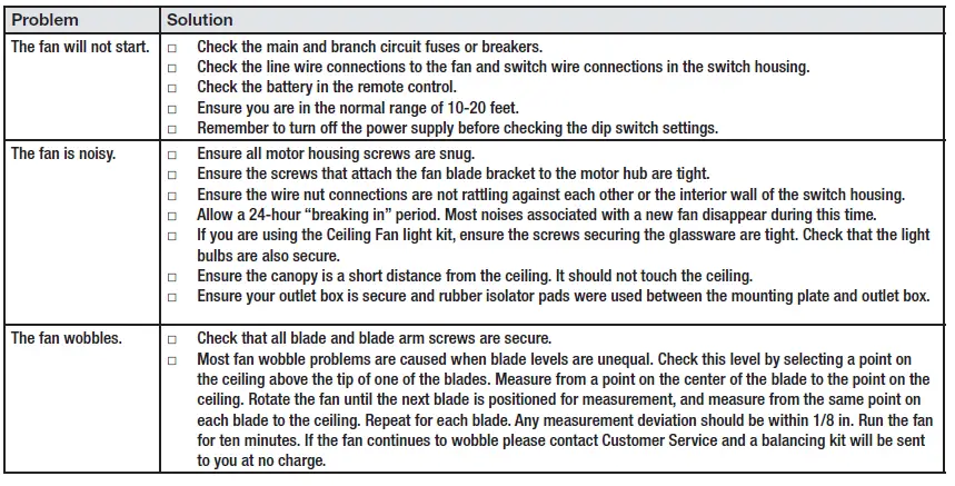
Attach wheel kit (J) to base (I). Line up holes in whe el bracket with corresponding holes in base, insert two bolts M8 x 16 (BB) through holes, and finger tighten two M8 flange nuts (AA). Reverse the base (I), fix the ground fixer (PP) to the base with two bolts M6X10 (QQ) and two washers Φ6 (HH), Secure the ground fixer (PP) with two nuts M6 (RR). Fix another two ground fixer (PP) with bolts and nuts, and reverse the base (I).
Note: To secure the unit, please use three nails M8x100 (not included) to nail the unit to the ground.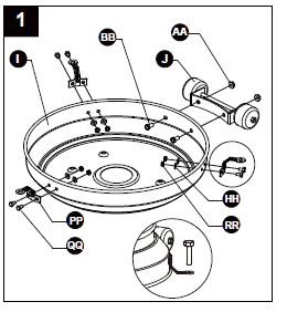
Hardware Used
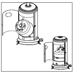
Attach cylinder housing (G) to base. Attach cylinder housing loosely to base with four M5 X 8 screws (CC).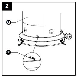
3. Attach post (H) to cylinder housing top. Open the door, put post through the hole on the top of cylinder housing.
Attach post to cylinder housing using the reinforced ring (NN), four M6 X 10 bolts (DD) and small flat washers Φ6 (EE). Fasten them and cover with the deck ring (OO)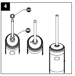
Table Installation. 5-1. Revised the table (D). Attached the table connector (E) to the table, secure them with four M5X 8 screws (CC).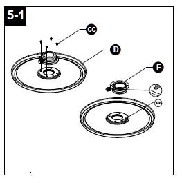
5-2. Turn the handle of connector in a clockwise direction, put the hole in the middle of the table through the pole. Turn the table in a clockwise direction to tighten and in a counter-clockwise direction to loosen.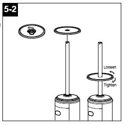
Attach reflector spacers (FF) and three washers Ø8 (GG) to screen cover. Tighten the reflector spacers.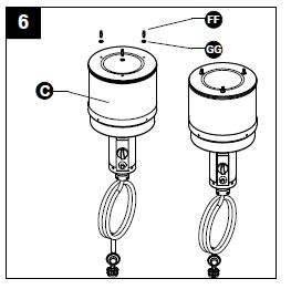
Attach head assembly to post. 7-1. Unscrew four stainless steel bolts (LL)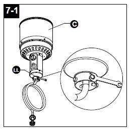
Load head assembly by inserting hose into post. Insert head assembly into post. Attach head assembly to post, and loosely install four stainless steel bolts. Tighten bolts securely. Note: The control knob on head assembly should be above the decal on post. When applicable, visually checking portions of the hose assembly located within the confines of the heater post.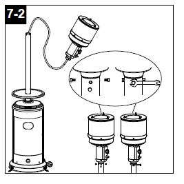
Remove protective cover before assembling. Note: If necessary for proper alignment of reflector sections, loosen each bolt prior to further assembly and retighten after sections are aligned.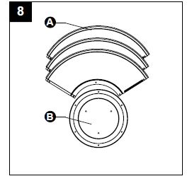
Slide two reflector panels together. Insert one screw M6 X 10 (II). Slide one washer Φ 6 (HH) over threaded end of screw M6 X 10 (II) and screw on cap nut (JJ) loosely.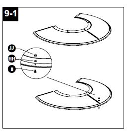
Slide reflector plate onto reflector panels. Insert one screw M6 X 10 (II). Slide one washer Φ 6 over threaded end of screw M6 X 10 (II) and screw on cap nut (JJ) loosely. Repeat procedure to complete the assembly of all four sections. Fully tighten all of the screws in the rolled edge.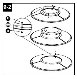
Support heater. Slide three washers washer Φ8 (GG) over threaded end of spacer. Locate reflector assembly on 3 spacers. Install three washers Φ8 on spacers and securely tighten wing nuts (KK) but do not overtighten.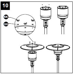
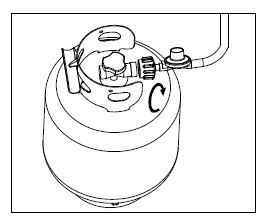
Connect hose and regulator to cylinder. The propane gas and cylinder are sold separately.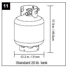
every part of the heater shall be secure against displacement and shall be constructed to maintain a fixed relationship between essential parts under normal and reasonable conditions of handling and usage. Parts not permanently secured shall be designed so they cannot be incorrectly assembled and cannot be improperly located or misaligned in removing or replacing during cleaning or other servicing. Use a standard 20 lb. propane cylinder only (approximately 12.2 in. / 31cm. in diameter and 17.9 in. / 45.5cm high). Use this heater only with a propane vapor withdrawal supply system. See chapter 5 of the standard for storage and handling of liquefied petroleum gas, ANS/NFPA 58. Your local library or fire department should have this book. Storage of an appliance indoors is permissible only if the cylinder is disconnected and removed from the appliance. A cylinder must be stored outdoors in a well-ventilated area out of the reach of children. A disconnected cylinder must have dust caps tightly installed and must not be stored in a building, garage or any other enclosed area. The maximum inlet gas supply pressure: 250 psi /1750 kPa. The minimum inlet gas supply pressure: 25 psi /175 kPa. Manifold pressure with regulator provided: 11 inch W.C/ 2.74 kPa. The pressure regulator and hose assembly supplied with the appliance must be used. The installation must conform with local codes, or in the absence of local codes, with national fuel gas code, ANS Z223.1/NFPA54, natural gas and propane Installation Code, CSA B149.1, or propane storage and handling code, B149.2. The knob on the LP tank must be closed. Make sure that the knob is turned clockwise to a full stop. The cylinder supply system must be arranged for vapor withdrawal. Check that the control knob on the control unit is turned off. Hold the regulator in one hand and insert the nipple into the valve outlet. Be sure the nipple is centered in the valve outlet. The coupling nut connects to the large outside threads on the valve outlet. Hand-tighten the coupling nut clockwise until it comes to a full stop. Firmly tighten by hand only. To Disconnect: Fully close the tank valve by turning clockwise. Turn the coupling nut counterclockwise until the regulator assembly detaches. A dented, rusted or damaged propane cylinder may be hazardous and should be checked by your cylinder supplier. Never use a propane cylinder with a damaged valve connection. The propane cylinder must be constructed and marked in accordance with the specifications for LP gas cylinders of the U.S. Department of Transportation (DOT) or the standard for cylinders, spheres and tubes for transportation of dangerous goods and commission, CAN/CSA-B339. The cylinder must have a listed overfilling prevention device. The cylinder must have a connection device compatible with the connection for the appliance. The cylinder used must include a collar to protect the cylinder valve. Never connect an unregulated propane cylinder to the heater. Screw regulator onto gas hose. Do not cross-thread. Tighten securely. Attach regulator to cylinder. Complete attachment. Install cylinder.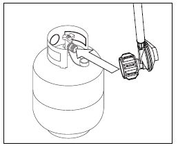
- Do not store a spare LP-gas cylinder under or near this appliance;
- Never fill the cylinder beyond 80 percent full;
- Place the dust cap on the cylinder valve outlet whenever the cylinder is not in use. Only install the type of dust cap on the cylinder valve that is provided with the cylinder valve. Other type of caps or plugs may result in leakage of propane.”
OPERATION INSTRUCTIONS
Leak Check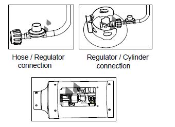
- Make 2-3 oz. of leak check solution (one part liquid dishwashing detergent and three parts water).
- Apply several drops of solution where hose attaches to regulator.
- Apply several drops of solution where regulator connects to cylinder.
- Make sure all patio heater and light valves are OFF.
- Turn cylinder valve ON.
If bubbles appear at any connection, there is a leak.
- Turn cylinder valve OFF.
- If leak is at hose/regulator connection: tighten connection and perform another leak test. If bubbles continue appearing, the hose should be returned to the place of purchase.
- If leak is at regulator/cylinder valve connection: disconnect, reconnect, and perform another leak check. If you continue to see bubbles after several attempts, cylinder valve is defective and should be returned to cylinder’s place of purchase. If NO bubbles appear at any connection, the connections are secure.
NOTE: Whenever gas connections are loosened or removed, you must perform a complete leak test. 4. Complete installation.
Before Turning Gas Supply ON
- Your heater was designed and approved for outdoor use only. Do NOT use it inside a building, garage, or any other enclosed area.
- Make sure surrounding areas are free of combustible materials, gasoline, and other flammable vapors or liquids.
- Ensure that there is no obstruction to air ventilation. Be sure all gas connections are tight and there are no leaks.
- Be sure the cylinder cover is clear of debris. Be sure any component removed during assembly or servicing is replaced and fastened prior to starting.
Before Lighting
- Heater should be thoroughly inspected before each use, and by a qualified service person at least annually. If relighting a hot heater, always wait at least 5 minutes.
- Inspect the visible portion of the hose before each use of the appliance. If the hose leaks, it must be replaced prior to operation. Only use the replacement hose assembly specified by manufacturer.
- The pressure regulator and hose assembly supplied with the appliance must be used. Replacement pressure regulators and hose assemblies must be those specified by the appliance manufacturer.
Lighting
- Turn on the valve on the gas cylinder.
- Press and turn the control knob to HIGH (maximum) position (counter-clockwise 90º). (Figure 1)
- Holding down the control knob, press the igniter button several times until the main flame is ignited. Release the control knob 10 seconds after the ignition.
- Turn the control knob to LOW (minimum) and leave it there for 5 minutes or more before turning the knob to the desired temperature setting. (Figure 2)
- If the burner flame goes out, turn off the heater and wait at least 5 minutes or more to let the gas dissipate before re-lighting to avoid gas explosion. Repeat steps 2 to 4.
Note: Improper operation, can cause injury or property damage. If burner fails to remain lit, all valves should be closed and a waiting period of at least 5 minutes should pass before attempting to light.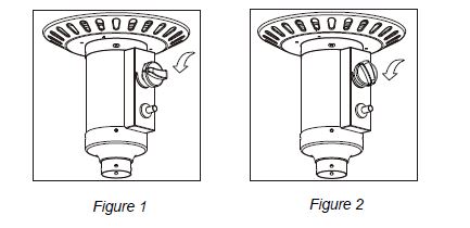
If you experience any ignition problem please consult “Troubleshooting” on page 18. Caution: Avoid inhaling fumes emitted from the heater’s first use. Smoke and odor from the burning of oils used in manufacturing will appear. Both smoke and odor will dissipate after approximately 30 minutes. The heater should NOT produce thick black smoke. Note: The burner may be noisy when initially turned on. Turn the knob to the level of heat desired.
When Heater is ON:
Emitter screen will become bright red due to intense heat. The color is more visible at night. Burner will display tongues of blue and yellow flame. These flames should not be yellow or produce thick black smoke, indicating an obstruction of airflow through the burners. The flame should be blue with straight yellow tops. If excessive yellow flame is detected, turn off heater and consult “Troubleshooting” on page 18.
Re-lighting
- Turn control knob to OFF.
- Repeat the “Lighting” steps on prior page.
Shut Down
Turn cylinder valve clockwise to OFF and disconnect regulator when heater is not in use. Note: After use, some discoloration of the emitter screen is normal.
Operation Checklist For a safe and pleasurable heating experience, perform this check before each use.
Before Operating
- I am familiar with entire owner’s manual and understand all precautions noted.
- All components are properly assembled, intact and operable.
- No alterations have been made.
- All gas connections are secure and do not leak.
- Wind velocity is below 10 mph.
- Unit will operate at reduced efficiency below 40°F.
- Heater is outdoors (outside any enclosure).
- There is adequate fresh air ventilation.
- Heater is away from gasoline or other flammable liquids or vapors.
- Heater is away from windows, air intake openings, sprinklers and other water sources.
- Heater is at least 3 feet on top and at least 3 feet on sides from combustible materials.
- . Heater is on a hard and level surface.
- There are no signs of spider or insect nests.
- All burner passages are clear.
- All air circulation passages are clear.
- Children and adults should be alerted to the hazards of high surface temperatures and should stay away to avoid burns or clothing ignition.
- Young children should be carefully supervised when they are in the area of the heater.
- Clothing or other protective material should not be hung from the heater, or placed on or near the heater.
- Any guard or other protective device removed for servicing the heater must be replaced prior to operating the heater.
- Installation and repair should be done by a qualified service person. The heater should be inspected before use and at least annually by a qualified service person.
- More frequent cleaning may be required as necessary. It is imperative that control compartment, burner and circulating air passageways of the heater be kept clean.
After Operation
- Gas control is in OFF position.
- Gas tank valve is OFF.
- Disconnect gas line.
CARE AND MAINTENANCE
To enjoy years of outstanding performance from your heater, make sure you perform the following maintenance activities on a regular basis:
Keep exterior surfaces clean.
- Use warm soapy water for cleaning. Never use flammable or corrosive cleaning agents.
- While cleaning your unit, be sure to keep the area around the burner assembly dry at all times. Do not submerge the control valve assembly. If the gas control is submerged in water, do NOT use it. It must be replaced.
- Keep the appliance area clear and free from combustible materials, gasoline and other flammable vapors and liquids.
- Do not obstruct the flow of combustion and ventilation air.
- Keep the ventilation opening(s) of the cylinder enclosure free and clear from debris.
- Air flow must be unobstructed. Keep controls, burner, and circulating air passageways clean.|
Visually checking portions of the hose assembly located within the confines of the heater post. Inspect the entire hose assembly at least annually, disassembling the reflector and burner. Inspect the hose assembly for evidence of excessive abrasion, cuts, or wear. Suspected areas should be leak tested. Then assembling the reflector and burner again following with step 6 and 10. Gas odor with extreme yellow tipping of flame. Heater does NOT reach the desired temperature. Heater glow is excessively uneven. Heater makes popping noises. Spiders and insects can nest in burner or orifices. This dangerous condition can damage heater and render it unsafe for use. Clean burner holes by using a heavy-duty pipe cleaner. Compressed air may help clear away smallerparticles. Carbon deposits may create a fire hazard. Clean dome and burner screen with warm soapy water if any carbon deposits develop. Note: In a salt-air environment (such as near an ocean), corrosion occurs more quickly than normal. Frequently check for corroded areas and repair them promptly.
Storage
Between uses: Turn Control Knob OFF. Disconnect LP source. Store heater upright in an area sheltered from direct contact with inclement weather (such as rain, sleet, hail, snow, dust and debris). If desired, cover heater to protect exterior surfaces and to help prevent build-up in air passages. Note: Wait until heater is cool before covering. During periods of extended inactivity or when transporting: Turn Control Knob OFF. Disconnect LP source and move to a secure, well-ventilated location outdoors. Store heater upright in an area sheltered from direct contact with inclement weather (such as rain, sleet, hail, snow, dust and debris). If desired, cover heater to protect exterior surfaces and to help prevent build-up in air passages. Never leave LP cylinder exposed to direct sunlight or excessive heat.
Note: Wait until heater is cool before covering.
Service
Only a qualified service person should repair gas passages and associated components. Caution: Always allow heater to cool before attempting service.
TROUBLESHOOTING
| PROBLEM | POSSIBLE CAUSE | CORRECTIVE ACTION |
|
Burner won’t light |
Propane cylinder is frosted over | Wait until the propane cylinder warms up and is defrosted |
| Blockage in orifice | Clear blockage | |
| Control knob is not in ON position | Turn control knob to ON | |
|
Burner flame is low |
Gas pressure is low | Turn cylinder valve OFF and replace cylinder |
| Outdoor temperature is less than 40ºF and tank is less than 1/4 full | Use a full cylinder | |
| Control knob fully ON | Check burner and orifices for blockage | |
| Carbon build-up
Thick black smoke |
Dirt or film on reflector and burner screen | Clean reflector and burner screen |
| Blockage in burner | Remove blockage and clean burner inside and outside |
ONE-YEAR LIMITED WARRANTY
This product is inspected, tested and carefully packaged to minimize the chance of damage during shipment. If a part within one year from the date of purchase proves to be defective in material or fabrication under normal use, the part will be repaired or replaced. The Company’s obligation under the warranty is to replace or repair defective parts at our discretion. Any expenses or damage resulting from the installation, removal or transportation of the product will the responsibility of the owner and are not covered by this warranty. The owner assumes all other risks arising out from the use or misuse of the product. The warranty will be void if the product damage or failure is deemed by the Company to be caused by accident, alteration, misuse, abuse, incorrect installation or removal, or connection to an incorrect power source by the owner. The Company neither assumes, nor authorizes any person or entity to assume for it any obligation or liability associated with its products.
* Light bulbs and fuses are not covered under this warranty.
Manufactured by: Jiangsu Gardensun Furnace Co., Ltd. Xinwu Village Zouqu Town Changzhou City Jiangsu Province P.R. China Tel: 86-519-83317471 Fax: 86-519-83315116 Http: www.jiadeshun.com Email: [email protected] For additional assistance or service, please call: 1-855-885-5858.
REPLACEMENT PARTS LIST
| PART DESCRIPTION QUANTITY | ||
| A | Reflector Panel | 3 |
| B | Reflector Plate | 1 |
| FF | Reflector Stud | 3 |
| C | Head Assembly | 1 |
| D | Tabletop | 1 |
| E | Table connector | 1 |
| F | Regulator(pre-assembled in C) | 1 |
| OO | Deck Ring | 1 |
| NN | Reinforced Ring | 1 |
| G | Cylinder Housing | 1 |
| H | Post | 1 |
| I | Base | 1 |
| J | Wheel Kit | 1 |

Use and Care Guide Solar LED Path Light
Item #1006 619 035 Model #93192
PACKAGE CONTENTS
|
|||||
| A – Solar Head with bulb x 4 | B – AA 1.2V 1000mAh Ni-Mh rechargeable battery (pre-installed) x 4 | C – Battery cover x 4 | D – Housing x 4 | E – Post x 4 | F – Stake x 4 |
PLANNING FOR A SUCCESSFUL ASSEMBLY
- Read all instructions before assembly and installation.
- Inspect each part for defects that may have occurred during shipping.
- Keep your receipt and these instructions for proof of purchase.
CHOOSING THE RIGHT LOCATION
Install your solar light in a location with full, direct sunlight. Do not install in shaded areas as these areas will not allow the batteries to fully charge and will reduce the nighttime operating hours for your light. Ensure that the installation location is away from other nighttime light sources such as street or porch lamps. These light sources may prevent your solar light from automatically turning on.
HOW SOLAR WORKS
The solar light has a solar panel that converts sunlight into electricity. During the day, the converted electricity is stored in the rechargeable batteries. At night, the solar light is powered by the batteries using the electricity stored during the day. The operating time depends on geographical location, daily weather conditions, and season. For optimal performance during the evening, allow the batteries to charge for 6 to 7 hours in direct sunlight.
Assembly and Installation
- Preparing for installation
- FOR FIRST TIME USE: Twist and remove the solar head (A) from the housing (D). Keep the switch in the “ON” position.
- Replace the solar head (A) on the housing (D).
- Firmly slide the post (E) into the solar housing (D).
- Attach the post (E) to stake (F).
2. Installing the solar light in the ground NOTE: Do not use a hammer. If the ground is hard, use water to soften or a trowel to loosen the soil.
- Push the assembly firmly into the ground.
Maintenance
Replacing the battery CAUTION: When replacing the battery, use one (1) 1000 mAh NiMH AA 1.2V rechargeable battery. IMPORTANT: Dispose of the batteries in accordance with local, state, and federal regulations.  NOTE: For best performance, replace with a rechargeable 1.2V NiMH battery of 1000 mAh or greater every 3 years or when performance diminishes.
- Twist and remove the housing (D) from top cover (A).
- Remove the battery cover (C). Replace the old battery with a fresh AA NiMH 1000 mAh rechargeable battery.
- Replace the battery cover (C) and housing (D). Charging the battery
- For optimum performance, it is best to install the solar light in full sunlight and let it charge for 6-7 hours.
- Allow the light to run at least 8-12 entire charging and discharging cycles to reach the maximum capacity of the battery.
Winter tips
- Keep debris and snow off the solar panel to allow the battery to recharge. If lights have been covered by snow for a long time, allow the battery to recharge in full, direct sunlight for at least 6-7 hours so it can maintain maximum capacity.

Troubleshooting
| Problem | Solution |
| The nightly runtime for the lights is shorter. | The battery is not adequately charged. Locate the solar light in an area where it can receive the maximum amount of full, direct sunlight every day. The battery is reaching the end of its useful life. Replace the old battery with a new battery. |
| The lights do not turn on in the evening. | The solar panel is installed close to other light sources. Relocate the solar panel or eliminate the other light sources. |
Care & Cleaning
- Clean the solar panel with a damp cloth. Do not use any chemicals or abrasives.
Warranty
The manufacturer warrants this product to be free for two (2) years against any defects that are due to faulty materials or workmanship. This warranty applies only to the original consumer and only to products used in normal use and service. If this product is found to be defective, the manufacturer’s only obligation, and your exclusive remedy, is the repair or replacement of the product at the manufacturer’s discretion, provided that the product has not been damaged through misuse, abuse, accident, modifications, alterations, neglect or mishandling. This warranty shall not apply to any product that is found to have been improperly installed, set up, or used in any way not in accordance with the instructions supplied with the product. This warranty shall not apply to a failure of the product as a result of an accident, misuse, abuse, negligence, alteration, or faulty installation or any other failure not relating to faulty workmanship. This warranty shall not apply to the finish on any portion of the product, such as surface and/or weathering, as this is considered normal wear and tear. The manufacturer does not warrant and specifically disclaims any warranty, whether expressed or implied, or fitness for a particular purpose, other than the warranty contained herein. The manufacturer specifically disclaims any liability and shall not be liable for any consequential or incidental loss or damage, including any labor/expense costs involved in the replacement or repair of said product. Contact the Customer Service Team at 1-855-HD-HAMPTON or visit www.HamptonBay.com.
SPECIFICATIONS
| Brand | Hampton Bay |
| Model | 93192 |
| Type | Solar LED Path Light |
| Package Contents | Solar Head with bulb x 4, AA 1.2V 1000mAh Ni-Mh rechargeable battery (pre-installed) x 4, Battery cover x 4, Housing x 4, Post x 4, Stake x 4 |
| Installation Location | Full, direct sunlight; away from other nighttime light sources |
| Battery | AA 1.2V 1000mAh Ni-Mh rechargeable battery |
| Battery Life | Replace every 3 years or when performance diminishes |
| Charging Time | 6-7 hours in direct sunlight |
| Operating Time | Depends on geographical location, daily weather conditions, and season |
| Maintenance | Replace battery every 3 years or when performance diminishes; clean solar panel with damp cloth |
| Warranty | 2-year warranty against defects due to faulty materials or workmanship |
FAQS
What is included in the package contents of the Hampton Bay Solar Pathway Lights Model 93192?
The package contents include four solar heads with bulbs, four AA 1.2V 1000mAh Ni-Mh rechargeable batteries, four battery covers, four housings, four posts, and four stakes.
How should I plan for a successful assembly of the Hampton Bay Solar Pathway Lights Model 93192?
Read all instructions before assembly and installation. Inspect each part for defects that may have occurred during shipping. Keep your receipt and these instructions for proof of purchase.
How do I choose the right location for installation of the Hampton Bay Solar Pathway Lights Model 93192?
Install your solar light in a location with full, direct sunlight. Do not install in shaded areas as these areas will not allow the batteries to fully charge and will reduce the nighttime operating hours for your light. Ensure that the installation location is away from other nighttime light sources such as street or porch lamps. These light sources may prevent your solar light from automatically turning on.
How does solar energy work for the Hampton Bay Solar Pathway Lights Model 93192?
The solar light has a solar panel that converts sunlight into electricity. During the day, the converted electricity is stored in the rechargeable batteries. At night, the solar light is powered by the batteries using the electricity stored during the day. The operating time depends on geographical location, daily weather conditions, and season. For optimal performance during the evening, allow the batteries to charge for 6 to 7 hours in direct sunlight.
How do I replace the battery of the Hampton Bay Solar Pathway Lights Model 93192?
Twist and remove the housing (D) from top cover (A). Remove the battery cover (C). Replace the old battery with a fresh AA NiMH 1000 mAh rechargeable battery. Replace the battery cover (C) and housing (D).
How do I charge the battery of the Hampton Bay Solar Pathway Lights Model 93192?
For optimum performance, it is best to install the solar light in full sunlight and let it charge for 6-7 hours. Allow the light to run at least 8-12 entire charging and discharging cycles to reach the maximum capacity of the battery.
What should I do during winter to maintain the Hampton Bay Solar Pathway Lights Model 93192?
Keep debris and snow off the solar panel to allow the battery to recharge. If lights have been covered by snow for a long time, allow the battery to recharge in full, direct sunlight for at least 6-7 hours so it can maintain maximum capacity.
What should I do if the nightly runtime for the lights is shorter for the Hampton Bay Solar Pathway Lights Model 93192?
The battery is not adequately charged. Locate the solar light in an area where it can receive the maximum amount of full, direct sunlight every day. The battery is reaching the end of its useful life. Replace the old battery with a new battery.
What should I do if the lights do not turn on in the evening for the Hampton Bay Solar Pathway Lights Model 93192?
The solar panel is installed close to other light sources. Relocate the solar panel or eliminate the other light sources.
How do I care and clean the Hampton Bay Solar Pathway Lights Model 93192?
Clean the solar panel with a damp cloth. Do not use any chemicals or abrasives.
What is the warranty for the Hampton Bay Solar Pathway Lights Model 93192?
The manufacturer warrants this product to be free for two (2) years against any defects that are due to faulty materials or workmanship. This warranty applies only to the original consumer and only to products used in normal use and service. If this product is found to be defective, the manufacturer’s only obligation, and your exclusive remedy, is the repair or replacement of the product at the manufacturer’s discretion, provided that the product has not been damaged through misuse, abuse, accident, modifications, alterations, neglect or mishandling.
HAMPTONBAY.COM Please contact 1-855-HD-HAMPTON for further assistance.
]]>HAMPTON BAY Beacon Park Steel Woven Swivel Chair

Import ant Safety Instructions
WARNING: This swivel chair was made for the explicit purpose of providing outdoor functions and is not to be used as a toy. This product is intended for normal outdoor use; however, the manufacturer recommends storing and / or covering this product when any formidable / severe weather is approaching.
To reduce the risk of injury to persons:
- Close supervision is necessary when this product is used by or near children, or disabled persons, if applicable.
- Use this product only for its intended use as described in these instructions. Do not use attachments not recommended by the manufacturer.
- Do not move the chair while the chair is occupied. Failure to obey this caution could result in injury.
- Please keep children out of the assembly area before assembly.
WARNING: Do not place heavy objects on the chair
WARNING: Weight limit for chair is 300 lbs (136.07 Kg) for each seat.
WARNING: This chair unit is heavy, and may require two adults for safe assembly.
CAUTION: Do not locate the product near any! heat source.
Warranty
3 YEAR FRAME AND 3 YEAR FABRIC LIM ITED WARRANTY
WHAT IS COVERED
We warrant the frames to be free of manufacturing defects to the original purchaser for three years, and a three year limited warranty for the fabric.
WHAT IS NOT COVERED
It remains the customer’s responsibility for freight and packaging charges to and from our service center. This warranty does not cover commercial use, hardware, acts of nature, fire, freezing and abusive use. In addition, purchased parts are not covered under this warranty. We reserve the right to make substitutions with similar merchandise, if the model in question is no longer in production. Contact the
Customer Service Team at 1-855-HD-HAMPTON or visit www.Hamptonbay.com
Pre-Assembly
PLANNING ASSEMBLY
Read all instructions before assembly.
To avoid damaging this product, assemble it on a soft, non-abrasive surface such as carpet or cardboard.
HARDWARE INCLUDED
NOTE: Hardware not shown to actual size.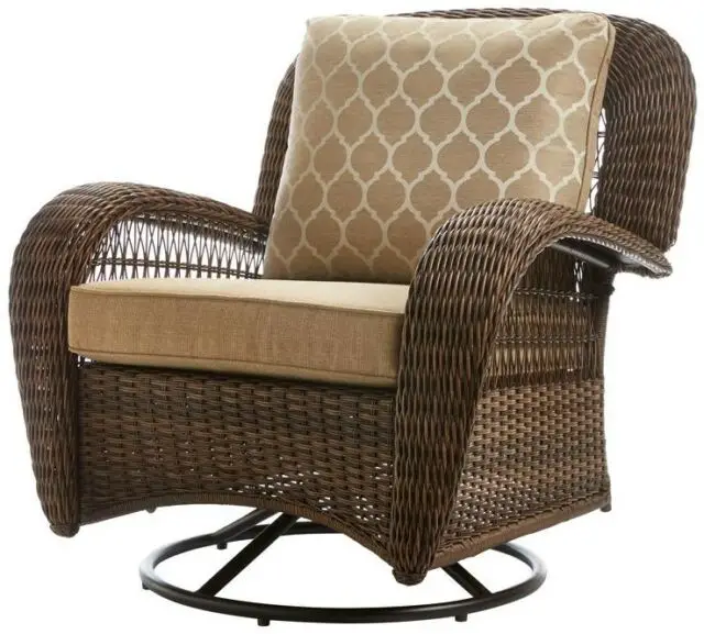
| Part | Description | Quantity |
| AA | M6x20 combination bolt | 6+1 |
| BB | M6x50 combination bolt | 4+1 |
| CC | M6x18 countersunk bolt | 4 |
| DD | M6 plastic washer | 4 |
| EE | Hex wrench | 1 |
PACKAGE CONTENTS
| Part | Description | Quantity |
| A | Right arm | 1 |
| B | Left arm | 1 |
| C | Seat | 1 |
| D | Backrest | 1 |
| E | Glider base | 1 |
| F | Swivel base | 1 |
| G | Back cushion | 1 |
| H | Seat cushion | 1 |
CONNECTING THE RIGHT ARM TO THE SEAT
- Place the right arm (A) on a soft surface.
- Do not fully tighten all bolts at this step.
- Align the holes on the right panel of the seat (C) to the holes on the front of the right arm (A), and secure by using M6x20 combination bolts (AA).

ATTACHING THE BACKREST TO THE SEAT AND THE RIGHT ARM
- Attach the backrest (D) to the right arm (A) and the seat (C) using an M6x20 combination bolt (AA) and M6x50 combination bolts (BB).
- Do not fully tighten all bolts at this step.
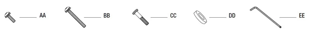
CONNECTING THE LEFT ARM TO THE SEAT AND THE BACKREST
- Connect the left arm (B) to the seat (C) and the backrest (D) using M6x20 combination bolts (AA).
- Do not fully tighten all bolts at this step.
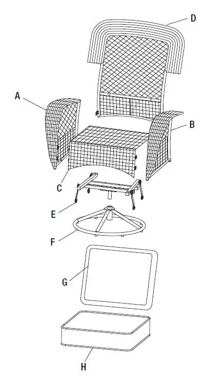
CONNECTING THE ARMS TO THE BACKREST
- Connect the back of the right and the left arm (A & B) to the backrest (D) by inserting M6x50 combination bolts (BB).
- Do not fully tighten all bolts at this step.
ATTACHING THE GLIDER BASE TO THE ARMS
- Attach the glider base (E) to the arms (A & B) using M6x18 countersunk bolts (CC) and M6 plastic washers (DD).
- Do not fully tighten all bolts at this step.
TIGHTENING ALL BOLTS, CONNECTING THE SUPPORT BAR TO THE SWIVEL BASE
- Once all of the bolts are in place, fully tighten the bolts using the hex wrench (EE).
- Turn the chair right side up, and insert the support bar to the swivel base (F).
CHECKING THE CHAIR
- Place the seat and the back cushion (H & G) to finish the assembly of the chair.
- Ensure all connections are secure before use.
Care and Cleaning
- For best results, clean the chair with a damp cloth and dry thoroughly. This will help prevent mildew by removing dirt particles that may accumulate.
- Do not clean with abrasive materials, bleach, or solvents.
- Store the chair in a dry, sheltered place when not in use.
- Keep the chair away from fire, extreme heat, freezing conditions, and inclement weather such as rain, hail, sleet, snow, or wind.
Questions, problems, missing parts? Before returning to the store,
call Hampton Bay Customer Service.
8 a.m. – 7 p.m., EST, Monday – Friday, 9 a.m. – 6 p.m., EST, Saturday
Retain this manual for future use.
1-855-HD-HAMPTON
HAMPTONBAY.COM![]()